
No. 357,454 – Bench-Plane (John Brice) (1887)
UNITED STATES PATENT OFFICE.
_________________
JOHN BRICE, OF SANDY HILL, NEW YORK.
BENCH-PLANE.
_________________
SPECIFICATION forming part of Letters Patent No. 357,454, dated February 8, 1887.
Application filed March 16, 1886. Serial No. 195,420. (Model.)
_________________
To all whom it may concern:
Be it known that I, JOHN BRICE, a resident of Sandy Hill, in the county of Washington and State of New York, have invented certain new and useful Improvements in Bench-Planes; and I do hereby declare that the following is a full, clear, and exact description of the invention, that will enable others skilled in the art to which it appertains to make and use the same, reference being had to the accompanying drawings, and to the letters of reference marked thereon, which form a part of this specification.
My invention relates to improvements in bench~planes, and its object is fully explained in connection with the drawings.
The invention consists of the novel construction and combination of parts hereinafter described, and pointed out in the claims.
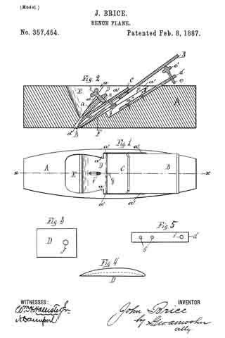
Figure 1 of the drawings is a top plan view of my improved plane. Fig. 2 is a vertical longitudinal section taken at the broken line x x in Fig. 1. Fig. 3 is a top plan view of my improved locking-lever. Fig. 4 is a side view of same. Fig. 5 is a plan view of attachment d detached.
Similar letters refer to similar parts in the several figures therein.
Numerous devices have been heretofore constructed for angularly adjusting the bit of a bench-plane and for securing the same in place in its frame or stock. They have generally been complicated in structure and expensive of manufacture, requiring special and differing forms of structure in the stock, the latter being generally made of metal.
In the construction of my improved device I am able to make use of the old and well-known wooden stock so generally in use, as well as the bit, or bit and back plate, used in connection therewith, and thus greatly improve such planes with very little expense.
My improved planes can also, when desired, be made wholly of metal or any other desirable material.
A is the stock, made in the well-known form usually adopted for wooden stocks, having the chip-opening E, inclined bit-abutment F, and upwardly-widening rearwardly-inclined side recesses, a’ a’, forming inclined ledges a a on each side of the chip-opening.
The bit B, which has a back plate, C, secured thereto by a set-screw, g, adjustable in its slot b’, is inserted through the opening in the usual manner, as shown.
Instead of driving a wedge down between the bit or plate C and the projecting ledges a a, to bind the bit in place, as has been done heretofore in such stocks, I make use of the locking-lever D, preferably metallic, and in the form of a plate convened on its upper side, substantially as shown.
I slide the lever down between the back plate, C, and the ledges a to about the position shown in Figs. 1 and 2.
The side of the lever contiguous to the plate C may have its surface plane or concave, as shown by dotted line in Fig. 4; but the opposite side contiguous to the ledges is convexed. The degree of convexity may be varied as desired.
At or near one end of the lever I provide the aperture f, preferably threaded, and adapted to receive the threaded adjusting screw b, the screw passing down through the aperture and resting upon the bit or its plate C.
When desired, a threaded nut, n, (shown by dotted lines,) may by employed, when it will not be necessary to thread the aperture in the lever.
By means of the adjusting-screw the upper end of the lever can be forced away from the plate C, the lower end of the screw resting upon the plate, and the lever traveling up the thread of the screw until the parts are securely locked in place, the central portion of the convexed lever ending a fulcrum upon the ledges a a, and the lower end of the lever bearing upon the lower end of the bit or its plate. I am able also to secure an angular adjustment of the bit by means of the attachment or plate d, extending above the top of the stock, provided with the adjusting-screw e, threaded to fit the threaded aperture i, having a head, e’, on which the bit has bearing. This attachment is preferably countersunk in a longitudinal recess, a”, in the upper or rear portion of the abutment F, to occupy a position about parallel with the bit, and may be secured by screws d’, passing through apertures j, as shown.
The upper end or head of the screw bears against the lower side of the bit, and when operated forces the bit up to the desired angle, the screw b being turned back, as required.
The convexity of lever D permits the angular adjustment of the bit to any desired degree without impairing the perfect operation and effectiveness of the lever as a locking device.
I am thus able to produce a new and improved plane by adding the loclring-lever D, with screw b, and the attachment d, with screw e, to a common and well-known device.
I do not broadly claim an angularly-adjustable bit nor a bit-locking lever.
What I claim as new, and desire to secure by Letters Patent, is —
1. The combination of the stock A, formed with a chip-opening, E, inclined rear abutment, F, having correspondingly-inclined longitudinal recess a”, upwardly-widening inclined side recesses, a’ a’, forming inclined front abutments, a a, projecting into the chip-opening, the fixed plane plate d, secured in the longitudinal recess and projecting above the stock, an adjusting-screw, e, inserted in the projecting portion, having a head, e’, a bit, B, supported on the inclined rear abutment and on the head of the adjusting-screw, the back plate, C, adjustably secured to the bit, and the lever D, located at the rear of the chip-opening, having a convex upper side bearing against the front abutments, its lower end bearing on the lower end of the back plate, and an adjusting-screw in the upper end of the lever bearing on the middle portion of the back plate, the bit, back plate, and lever all being of the sanie width and the side recesses being common to all, substantially as shown and described.
2. The combination of the stock A, formed with a chip-opening, E, longitudinal recess a”, and upwardly-widening inclined side recesses, a’ a’, forming inclined front abutments, a a, projecting into the chip-opening, the fixed plane plate d, having an adjusting-screw, e, a bit, B, a back plate, C, and the lever D, located at the rear of the chip-opening, having a convex upper side bearing against the front abutments, its lower end bearing on the lower end of the back plate, and an adjusting-screw in the upper end of the lever bearing on the middle portion of the back plate, the bit, back plate, and lever all being of the same width and occupying the side recesses common to all, substantially as shown and described.
In testimony whereof I have hereunto set my hand this 12th day of March, 1886.
JOHN BRICE.
Witnesses:
J. RADCLYFFE BRICE,
ELISHA D. BAKER.