
No. 1,085,651 – Guard For Hand-Planes (John E. Westberg) (1914)
UNITED STATES PATENT OFFICE.
_________________
JOHN E. WESTBERG, OF EL CAMPO, TEXAS.
GUARD FOR HAND-PLANES.
_________________
1,085,651. Specification of Letters Patent. Patented Feb. 3, 1914.
Application filed November 27, 1911. Serial No. 662,640.
_________________
To all whom it may concern:
Be it known that I, JOHN E. WESTBERG, a citizen of the United States, residing at El Campo, in the county of Wharton, State of Texas, have invented certain new and useful Improvements in Guards for Hand-Planes; and I do hereby declare the following to be a full, clear, and exact description of the invention, such as will enable others skilled in the art to which it appertains to make and use the same.
This invention relates to improvements in bench planes.
The principal object of the invention is to provide a guard for bench planes which will prevent the shavings or splinters from contacting with and injuring the hand of the operator.
Another object of the invention is to provide a guard for the purpose described which is in the nature of an attachment and which can therefore be readily applied to any plane now in common use which includes the usual front handle.
A further object of the invention is to provide a guard attachment for the purpose described, which is formed from a single blank of metal, is therefore simple in construction, and is cheap to manufacture.
With these and other objects in view, the invention consists in the construction and novel combination of parts hereinafter fully described, illustrated in the accompanying drawings, and pointed out in the claim hereto appended; it being understood that various changes in the form, proportion, size and minor details of construction within the scope of the claim, may be resorted to without departing from the spirit or sacrificing any of the advantages of the invention.
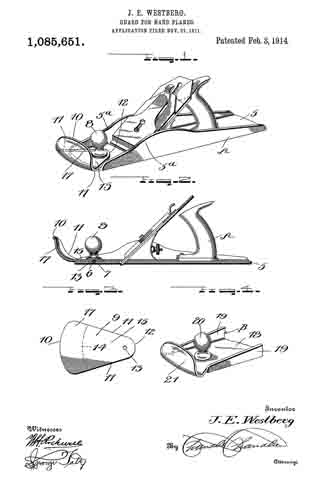
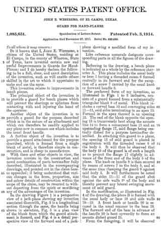
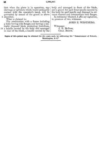
In the drawing Figure 1 is a perspective view of a jack-plane showing my invention associated therewith, Fig. 2 is a longitudinal section through the same, the handle being shown in elevation, Fig. 3 is a plan view of the blank from which the guard attachment is formed, and Fig. 4 is a detail perspective view of the forward end of a jack-plane showing a modified form of my invention.
Like reference numerals designate corresponding parts in all the figures of the drawing.
Referring to the drawing, a bench plane is indicated as a whole by the reference character A. This plane includes the usual body or base 5 having a threaded recess 6 formed centrally in its forward end for the reception of a screw 7 carried by the usual knob or forward handle 8.
The preferred form of my invention, as illustrated in Figs. 1 to 3 inclusive, consists of a guard formed from a substantially triangular blank 9 of metal. This blank includes a curved base 10 and converging sides 11–11, said sides terminating in an apex 12. Formed in the apex thereof is an opening 13. The end of the blank opposite the opening 13 is transversely bent along the arcuate line la to form a consequent base 15 and an upstanding flange 17, said flange being centrally dished for a purpose hereinafter described. In attaching this guard to a plane, the opening 13 of said guard is placed in registration with the threaded recess 6 of the body 5. It will thus be observed that the body 15 of the guard is of such a length as to project the flange 17 slightly in advance of the front end of the body 5 of the plane. The knob or handle 8 is then secured by means of screws 7 to the body 5, and at the same time clamping the guard 9 against said body 5. It will furthermore be noted that the sides 11–11 of the guard abut against the side walls 5a of the body and thereby prevent any lateral swinging movement of said guard.
In the modification, as illustrated in Fig. 4 of the drawing, the plane B is formed with the usual body or base 18 and side walls 19–19. A front knob or handle 20 is secured in the usual manner to the base 18. The forward end of the base in advance of the handle 20 is bent upwardly to form an arcuate dished guard 21.
From the foregoing, it will be observed that when the plane is in operation, any shavings or splinters which would ordinarily contact with the operator’s hand, will be prevented by means of the guard as above described.
What is claimed is:
The combination with a frame including a body having side flanges and having a centrally disposed blade projecting therefrom, a handle carried by the body and arranged in rear of the blade, a handle carried by the body and arranged in front of the blade, and a guard for said front handle secured to the body by said handle and disposed in advance thereof and intermediate said flanges.
In testimony whereof, I affix my signature, in presence of two witnesses.
JOHN E. WESTBERG.
Witnesses:
J. E. McIVER,
CHAS. BLOOM.
Copies of this patent may be obtained for five cents each, by addressing the “Commissioner of Patents, Washington, D. C.”
_________________