No. 620,226 – Joiner’s Plane (John M. Cole) (1899)


UNITED STATES PATENT OFFICE.
_________________
JOHN M. COLE, OF CLEVELAND, OHIO,
ASSIGNOR TO JOHN J. TOWER, OF NEW YORK, N. Y.
JOINER’S PLANE.
_________________
SPECIFICATION forming part of Letters Patent No. 620,226, dated February 28, 1899.
Application filed October 14, 1898. Serial No. 693,563. (No model.)
_________________
To all whom it may concern:
Be it known that I, JOHN M. COLE, a citizen of the United States, residing in the city of Cleveland, county of Cuyahoga, and State of Ohio, have invented certain new and useful Improvements in Joiners’ Planes; and I do hereby declare that the following is a full, clear, and exact description of the same, reference being had to the accompanying drawings, forming part of this specification.
My present invention relates to joiners’ or bench planes and is in the nature of an improvement upon the invention shown in Letters Patent No. 504,562, issued to me September 5, 1893.
The objects of my present invention are to render such planes convertible at will and to adapt them by simple and novel mechanisms for doing a very wide range of different classes of work without necessity of multiplicity or complication of parts, so that they may be of especial convenience and usefulness to journeyman workmen and others.
The leading feature of my present invention is comprised in such a construction and arrangement of the throat and of the bit holding and adjustment mechanisms as will permit ready substitution for the broad full-width bits commonly used in this class of planes of bits for different purposes of varying widths and any required conformation of cutting edge and in providing such mechanisms with a means and construction whereby these bits may by manipulation at the will of the operator without loss of time while at work be instantly and sensitively set farther and farther down just prior to each succeeding forward stroke when planing to plane to any desired depth into the wood below the bottom of the stock without blades, runners, or the usual depth-gages, so that with the use of any attachable and suitably adjustable or adjusted fence and of bits of required conformation joiners’ or bench planes may be instantly converted to do any of many classes of work, such as mitering, miter-grooving and miter-tonguing, tonguing, grooving, beading, center-beading, plowing, inside and outside fillistering or rabbeting, chamfering, slitting, dadoing, diagonal or cross-grain channeling, and edge-molding work of any description.
My invention is further comprised in a novel form of universally-adjustable single-rail fence specially well adapted for use in carrying out these features and in certain other novel forms, devices, functional arrangement, and combination of parts, all of which will hereinafter be fully described and claimed.
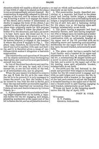
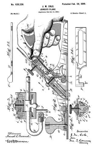
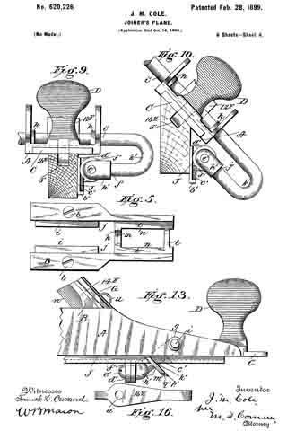
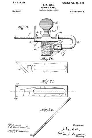
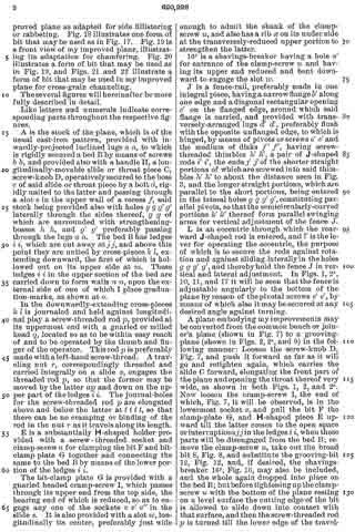
In the drawings, Figure 1 is a left-hand side elevation of a plane fully assembled containing all of my above-outlined improvements. Fig. 2 is a longitudinal central vertical sectional view of the same, with rear part of the stock and the handle shown in full and a hand shown in position on said handle, illustrating in part the construction and operation of the leading features of my invention. Fig. 2a is a left-hand side elevation similar to Fig. 1, with parts of the stock and fence broken away, further illustrating the operation of the leading features of my invention. Fig. 3 is a cross-section on dotted line 3 3 of Fig. 2, further illustrating the construction and operation of parts of my invention. Fig. 4 is a cross-section on dotted line 4 4 of Fig. 2, further illustrating the construction of certain parts. Fig. 5 is a top side view of the plane-bit bed. Fig. 6 is a bottom side view of the plane-bit clamp-plate with thumb cramp-screw in place. Fig. 7 is a longitudinal central vertical sectional view, similar to Fig. 2, of my improved plane with the fence removed, which represents the same as it is when used as a joiner’s or bench plane. Fig. 8 illustrates the usual type of broad bit used in Fig. 7. Fig. 9 is a front view of my improved plane adapted to grooving. Fig. 10 is a front view of same, showing its adaptation for mitering and miter-grooving. Fig. 11 is a front view of same, showing its adaptation for inside rabbeting and fillistering. Fig. 12 illustrates a grooving-bit. Fig. 13 is a right-hand side elevation further showing the construction, arrangement, and operation of my improved plane when used as shown in Fig. 11. Fig. 14 illustrates the form of bit that may be used in the work illustrated by Figs. 11 and 13. Fig. 15 is a slitting-bit which my improved plane is adapted to use. Fig. 16 is a plan view of a form of shavings-breaker, shown in Figs. 2 and 2a, which may be employed. Fig. 17 is a front view of my improved plane as adapted for side fillistering or rabbeting. Fig. 18 illustrates one form of bit that may be used as in Fig. 17. Fig. 19 is a front view of my improved plane, illustrating its adaptation for chamfering. Fig. 20 illustrates a form of bit that may be used as in Fig. 19, and Figs. 21 and 22 illustrate a form of bit that may be used in my improved plane for cross-grain channeling.
The several figures will hereinafter be more fully described in detail.
Like letters and numerals indicate corresponding parts throughout the respective figures.
A is the stock of the plane, which is of the usual cast-iron pattern, provided with inwardly-projected inclined lugs a a, to which is rigidly secured a bed B by means of screws b b, and provided also with a handle H, a longitudinally-movable slide or throat piece C, screw-knob D, operatively secured to the boss c of said slide or throat piece by a bolt d, rigidly united to the latter and passing through a slot e in the upper wall of a recess f, said stock being provided also with holes g g g’ g’ laterally through the sides thereof, g g of which are surrounded with strengthening-bosses h h, and g’ g’ preferably passing through the lugs a a. The bed B has ledges i i, which are cut away at j j, and above this point they are united by cross-pieces k l, extending downward, the first of which is hollowed out on its upper side at m. These ledges i i in the upper section of the bed are carried down to form walls n n, upon the external side of one of which I place graduation-marks, as shown at o.
In the downwardly-extending cross-pieces k l is journaled and held against longitudinal play a screw-threaded rod p, provided at its uppermost end with a gnarled or milled head q, located so as to be within easy reach of and to be operated by the thumb and finger of the operator. This rod p is preferably made with a left-hand screw-thread. A traveling nut r, correspondingly threaded and carried integrally on a slide s, engages the threaded rod p, so that the former may be moved by the latter up and down on the upper part of the ledges i i. The journal-holes for the screw-threaded rod p are elongated above and below the latter at t t t t, so that there can be no cramping or binding of the rod in the nut r as it travels along its length.
E is a substantially H-shaped holder provided with a screw-threaded socket and clamp-screw u for clamping the bit F and bit-clamp plate G together and connecting the same to the bed B by means of the lower portion of the ledges i i.
The bit-clamp plate G is provided with a gnarled headed cramp-screw I, which passes through its upper end from the top side, the bearing end of which is reduced, so as to engage any one of the sockets v v’ v” in the slide s. It is also provided with a slot w, longitudinally its center, preferably just wide enough to admit the shank of the clamp-screw u, and also has a rib as on its under side at the transversely-reduced upper portion to strengthen the latter.
16y is a shavings-breaker having a hole a’ for entrance of the clamp-screw u and having its upper end reduced and bent downward to engage the slot w.
J is a fence-rail, preferably made in one integral piece, having a narrow flange b’ along one edge and a diagonal rectangular opening c’ on the flanged edge, around which said flange is carried, and provided with transversely-arranged lugs d’ d’, preferably flush with the opposite unflanged edge, to which is hinged, by means of pivots or screws e’ e’ and the medium of disks f’ f’, having screw-threaded thimbles h’ h’, a pair of J-shaped rods i’ i’, the ends j’ j’ of the shorter straight portions of which are screwed into said thimbles h’ h’ to about the distance seen in Fig.
3, and the longer straight portions, which are parallel to the short portions, being entered in the lateral holes g g g’ g’, constituting parallel pivots, so that the semicircularly-curved portions k’ k’ thereof form parallel swinging arms for vertical adjustment of the fence J.
L is an eccentric through which the rearward J-shaped rod is entered, and l’ is the lever for operating the eccentric, the purpose of which is to secure the rods against rotation and against sliding laterally in the holes g g g’ g’, and thereby hold the fence J in vertical and lateral adjustment. In Figs. 1, 2a, 10, 11, and 17 it will be seen that the fence is adjustable angularly to the bottom of the plane by reason of the pivotal screws e’ e’, by means of which also it may be secured at any desired angle against turning.
A plane embodying my improvements may be converted from the common bench or joiner’s plane (shown in Fig. 7) to a grooving-plane (shown in Figs. 2, 2a, and 9) in the following manner: Loosen the screw-knob D, Fig. 7, and push it forward as far as it will go and retighten again, which carries the slide C forward, elongating the front part of the plane and opening the throat thereof very wide, as shown in both Figs. 1, 2, and 2a. Now loosen the cramp-screw I, the end of which, Fig. 7, it will be observed, is in the lowermost socket v, and pull the bit F the clamp-plate G, and H-shaped piece E upward till the latter comes to the open space or interruptions j j in the ledges i i, when these parts will be disengaged from the bed B; remove the clamp-screw u, take out the broad bit 8, Fig. 8, and substitute the grooving-bit 12, Fig. 12, and, if desired, the shavings-breaker 16y, Fig. 16, may also be included, and the whole again dropped into place on the bed B; but before tightening up the clamp-screw u with the bottom of the plane resting on a level surface the cutting edge of the bit is allowed to slide down into contact with that surface, and then the screw-threaded rod p is turned till the lower edge of the traveling nut is opposite the graduation-mark that indicates the desired depth to which the groove is to be planed, and now the cramp-screw I and clamp-plate G are lifted up till the end of the former drops into the uppermost socket v”, when the clamp-screw it is screwed down tight, and afterward the cramp-screw I is also screwed down with gentle tension. The J-shaped rods of the fence J are now entered in the holes g g g’ g’ and through the eccentric L the desired distance and the fence adjusted vertically to about the position shown in Fig. 9 and now securely clamped by the eccentric L. To convert to a mitering-plane, the fence is adjusted as shown by Fig. 10, and the broad bit 8f, Fig. 8, reinserted. To convert to a miter-grooving plane, take out the broad bit and restore bit 12f, Fig. 12, leaving the fence adjusted as shown in Fig. 10. With a proper bit miter-grooving can also by this last adjustment be done. To convert to an inside-rabbeting plane, an L-shaped bit 14f of the form shown by Fig. 14 is used, and the flanged edge b’ of the fence is turned under the bottom of the plane and adjusted to the position shown by Fig. 11, which brings the narrow portion m’ of the L-shaped bit within the opening c’ of the rail of the fence. To convert to an outside-rabbeting plane, a bit 18f of the form shown in Fig. 18 is substituted and substantially similar adjustment of the fence is maintained as shown by Fig. 17. To convert to a chamfering-plane, the fence is preferably adjusted to the position shown in Fig. 19 and a bit 20f of the shape shown in Fig. 20 is substituted. To do channeling, dadoing, or cross-grain work, bits constructed with cutting-lips n’ n’ at their lateral edges, as shown in Figs. 21 and 22, are employed, and the usual temporary gage is made fast to the board in which the channeling or dadoing is to be done as a guide in place of the fence which is removed. To convert to a slitting-tool, the bit, Fig. 15, would be substituted and the fence adjusted to the required position. These several above-described and any analogous conversions will be more readily understood by bearing in mind that they are attainable in a bench or joiner’s plane only in consequence of the leading feature of my invention — to wit, a construction of parts at the throat and provision in the mechanisms for holding movement and adjustment of the bits, whereby the cutting edge of the plane-bit, together with the shavings-breaker and bit-clamp plate, can be by regular gradations at the will of the operator advanced through the throat farther and farther down into the wood below the level of the bottom of the plane, and whereby (without employment of blades, runners, or gages) at each return stroke by a slight turn of the left-hand screw-threaded rod p with the thumb and finger the operator can cut as thin or as thick shavings as he chooses till the nut i has reached the limit of its movement, which, furthermore, may be adjusted to indicate any desired depth, as shown and described, while in the case of inside and outside rabbeting and fillistering a further element is brought into combination — viz., the opening c’ in the flanged edge of the rail of the fence J. The general utility of the improved construction, application and adaptation of the fence will be readily observed.
Those skilled in the art will fully comprehend that by my invention and with bits of required conformation of cutting edge and sole a very great diversity of work can be done, to accomplish which has heretofore required a number of special and in some cases very complicated and bulky planes.
It will be noted that my improved fence is reversible — i. e., may be applied to the right-hand side of the plane-stock, which is sometimes desirable.
I am aware that planes have been constructed with movable throat-pieces for regulating the “bite” of the bit and that such are, indeed, common; but I am not aware that any have before my present invention been adapted to allow of the passage of the cutting end of the bit, the bit-clamp plate, and shavings-breaker together bodily down through the same in the manner and for the purposes I have shown.
I am also aware that mechanisms for clamping and for very limited longitudinal adjustment of plane-bits have been made; but I am not aware that any have before my present invention been adapted for advancing the cutting edge of the bit by the sensitive will of the operator by any desired successional gradations while planing down through the throat of the plane into the wood any desired depth below the bottom of the plane and without the use of blades, runners, or depth-gages.
I am further aware that fences for planes with parallel pivoted arms have been made, and two-part angularly-adjustable rails for plane-fences have also been made; but I am not aware that before my present invention a one-part angularly-adjustable rail plane-fence provided with swinging parallel arms carrying integral parallel pivots and adapted for vertical and lateral adjustment has ever been used or that the rail in any adjustable fence has ever been constructed with an opening in the flanged edge for the purposes I employ the same.
I do not limit myself to the precise means described for accomplishing the gradual advance of the bit into the wood while using the plane, as manifestly other ways might be employed without departing from the spirit of my invention; but,
Having described my invention, what I do claim as new, and desire to secure by Letters Patent, is —
1. In a convertible joiner’s or bench plane, in combination, a widely open or widely-opening throat-piece, a longitudinally-slidable bit-holding mechanism comprising a clamp-plate and shavings-breaker plate adapted to hold vari-shaped bits and to be adjusted entirely through and beyond the throat, and a mechanical device suitably adapted for gradual, sensitive and rigid advancement of the shavings-breaker, bit-clamp plate and cutting end of such bits entirely through or beyond the throat while the plane is being used and at the will of the operator, substantially as and for the purposes shown and described.
2. In a convertible joiner’s or bench plane, in combination, a widely open throat or widely-opening throat-piece, a longitudinally-slidable bit-holding device comprising a clamp-plate and shavings-breaker plate adapted to hold vari-shaped bits and to be adjusted entirely through and beyond the throat, screw-actuated mechanism for gradual, sensitive and rigid advancement of the shavings-breaker, the bit-clamp plate and the cutting end of such bits entirely through or beyond the throat while the plane is being used and at the will of the operator, a one-rail removable, vertically, laterally and angularly adjustable fence, and mechanical means for rigidly securing said fence and its rail after adjustment, the whole constructed and to operate substantially as and for the purposes shown and described.
3. In combination, a convertible joiner’s or bench plane provided with a widely open throat or widely-opening throat-piece, a longitudinally-slidable bit-holding device comprising a clamp-plate and shavings-breaker plate adapted to hold vari-shaped bits and to be adjusted entirely through and beyond the throat, and a mechanical device suitably adapted for gradual, sensitive and rigid advancement of the shavings-breaker, bit-clamp plate and cutting end of such bits entirely through or beyond the throat while the plane is being used and at the will of the operator, a one-rail removable, vertically, laterally and angularly adjustable fence, and mechanical means for rigidly securing said fence and its rail after adjustment, for the purposes shown and described.
4. In combination with a convertible joiner’s or bench plane provided with a widely open throat or widely-opening throat-piece, and a bit-clamp adapted to hold vari-shaped bits to be adjusted entirely through or beyond the throat, a one-rail removable, laterally and angularly adjustable fence provided with an opening for passage of the bit through the flanged edge of said adjustable rail, substantially as and for the purposes shown and described.
5. In combination with a convertible joiner’s or bench plane constructed and to operate substantially as shown and described, a removable, vertically, laterally and angularly adjustable fence, parallel swinging arms, each having long and short integral pivots, the shorter ones pivotally united to the lugs of the rail of said fence by means of screw-threaded thimbles h’ h’ and right-angularly-arranged disks f’ f’, and mechanical means for rigidly securing said fence after adjustment, substantially as and for the purposes shown and described.
6. In a convertible joiner’s or bench plane, in combination, a vertically and laterally adjustable fence, parallel swinging arms, each having long and short integral pivots, lateral sockets in the plane-stock for the longer parallel pivots of said arms, and an eccentric for engagement of one of said long pivots, substantially as and for the purposes shown and described.
7. A convertible joiner’s or bench plane provided with a longitudinally-slidable bit-holding mechanism comprising a clamp-plate, and a shavings-breaker plate, and with mechanical means for gradual and rigid advancement of said shavings-breaker and bit-clamp plates and the cutting end of bits entirely through or beyond the throat while the plane is being used and at the will of the operator, in combination with graduation-marks adjacent to or upon said longitudinally-slidable bit-holding parts, substantially as and for the purposes shown and described.
8. In convertible joiners’ or bench planes, a screw-actuated mechanism adapted for gradual rigid advancement of the bit longitudinally, comprised of a clamp for holding the bit, a holder for connecting the same with the ledges of the bed, a slide provided with two or more sockets v v’ v”, a cramp-screw in the outer end of the clamp-plate to engage said sockets, a traveling nut, a longitudinally-immovable screw-threaded rod engaging said nut, provided with a gnarled head, in combination with a widely open throat or widely-opening throat-piece, constructed, arranged and adapted to be operated substantially as and for the purposes shown and described.
In testimony whereof I have hereunto set my hand, this 2d day of September, 1898, in the presence of two subscribing witnesses.
JOHN M. COLE.
Witnesses:
WARREN M. TOWER,
VINCENT ROSEMON.