No. 88,109 – Improvement In Plane-Guide (John Woodville) (1869)

[paiddownloads id=”150″]88109


United States Patent Office.


JOHN WOODVILLE, OF CINCINNATI, OHIO.

Letters Patent No. 88,109, dated March 23, 1869.
_________________

IMPROVEMENT IN PLANE-GUIDE.

_________________

The Schedule referred to in these Letters Patent and making part of the same.

_________________

To all whom it may concern:

Be it known that I, JOHN WOODVILLE, of Cincinnati, in the county of Hamilton, and State of Ohio, have invented a new and useful Improvement in Plane-Guide and Holder; and I do hereby declare that the following is a full, clear, and exact description thereof, which will enable others skilled in the art to make and use the same, reference being had to the accompanying drawings, forming part of this specification, in which —

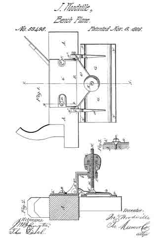
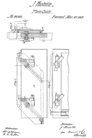
Figure 1 represents a back-side elevation of my improved apparatus;
Figure 2 represents afront-side elevation, with a part broken away; and
Figure 3 represents a transverse section taken on the line x x of fig. 1.

Similar letters of reference indicate like parts.

The object of this invention is to provide an adjustable holder, or clamp, for holding strips, for dressing them, and which will also serve as a guide for straightening or tapering them. It is designed more particularly to be used with the improved joiners’ plane, patented to me, November 6, 1866.

It consists of a holding-strip, or board, which is designed to be secured to a bench, with one edge upward, and which is provided with an adjustable gauge upon one side, against which the strips to be planed are clamped, by buttons and wedges on the other side of the first-mentioned holding-strip.

A represents the holding-strip, which may be secured to a bench, or in a vise, in any suitable manner, with the edge B upward.

C represents a guide and clamping-strip, which is provided with the T-headed inclined grooves D, whereby it is clamped to the strip A, by the bolts E and thumb-nuts E’; the heads F of the said bolts being arranged loosely thereon, and sliding in the wide part of the grooves D.

The holes through the strips A are elongated, and provided with the hollow bolts I, having enlarged heads arranged in the recesses H. The bolts E pass through these hollow bolts, and the office of the latter is to serve as rigid supports for the former when adjusted to the light position, and screwed up tightly by the nuts I’.

K represents clamping-buttons adjustably connected to the front face of the strip A, by the long bolts L; and

M represents wedges pivoted to the face of the strip A, in a position to be conveniently adjusted under the inclined ends of the buttons, for clamping them against the stuff to be operated upon.

The operation is as follows:

When it is designed to dress a strip with parallel and square edges, the guiding-strip C, which is provided with one edge a, and one bevelled edge b, is adjusted to the strip A, with the square edge a as high above the strip A as the designed width of the strip to be dressed the edge a being in a horizontal plane parallel with the edge of the strip A when it is clamped tight thereto by the bolts E and thumb-nuts E’.

The strip to be dressed is then placed upon the upper edge of the strip A, and clamped between the guide C and the buttons K.

The plane, which, according to the improvements patented to me as above described, is provided with an adjustable guide, d, is then placed upon the strips to be dressed, and held by the said guide, so that the edge e of the stock will project over the guide C sufficiently to arrest the cutting-action of the plane when the strip has been worked down to the point coincident with the edge of the guide C.

Any number of strips may thus be dressed to the same gauge with great uniformity, while at the same time the edges will be exactly square, if the plane-guide be adjusted to that angle.

If it is desired to dress the strips with bevelled edges, the bevelled edge b, of the guide G, is placed upward, as represented in blue lines, at b’; and if it be desired to produce tapered strips, the guide C may be adjusted to produce any taper, by loosening the bolts E and I, so as to allow the plates I to move in the recesses H, to correspond with the varying distances caused between the points of contact with the grooves D, of the heads of the bolts E, by changing the horizontal plane of the guide C.

In dressing thin strips, two or any other number, not wider in the aggregate than the plane-bit, may be clamped together, and dressed at once.

In dressing strips in this manner, in my improved guide and holder, with my improved planes, I have found it very desirable to provide the jack, or roughing-plane with an adjustable gauging-strip, f, as shown in red in fig. 3, for the purpose of arresting the cutting-action of the plane-bit, the amount of a few shavings, before the strips are brought down to a level with the upper edge of the guide C, so that the roughing-plane may be removed in time to finish the work by the jointer, which I provide with a similar guide, d, but not with the guide f

The latter may be adjustably connected to the stock, so that, as the latter wears away, it may be adjusted thereon.

I am aware that clamps have already been arranged upon carpenters’ benches in such a rnanner as to be adjustable for cutting different widths of boards with square or bevelled edges.

Having thus described my invention, I claim as new, and desire to secure by Letters Patent —

1. The combination of the clamping-bolts E and the sliding bolts I, with the supporting-strip A and grooved strip C, whereby said strips are held together, for dressing a board with either parallel or tapering sides, substantially as herein shown and described.

2. The combination, with the strips A and G, of the adjustable buttons K and pivoted wedges M, substantially as and for the purpose set forth.

JOHN WOODVILLE.

Witnesses:
FRANK BLOCKLEY,
ALEX. F. ROBERTS.

No. 59,498 – Improvement In Carpenters’ Planes (John Woodville) (1866)

[paiddownloads id=”120″]59498


UNITED STATES PATENT OFFICE.

_________________

JOHN WOODVILLE, OF CINCINNATI, OHIO.

IMPROVEMENT IN CARPENTERS’ PLANES.

_________________

Specification forming part of Letters Patent No. 59,498, dated November 6, 1866.

_________________

To all whom it may concern:

Be it known that I, JOHN WOODVILLE, of Cincinnati, in the county of Hamilton and State of Ohio, have invented a new and useful Improvement in Jointing-Planes; and I do hereby declare that the following is a full, clear, and exact description thereof, which will enable others skilled in the art to make and use the same, reference being had to the accompanying drawings, forming part of this specification, in which —

Figure 1 is a side view of a plane with my improvement attached. Fig. 2 is a cross-section of the same, taken through the line x x, Fig. 1. Fig. 3 is a detail sectional view of the same, taken through the line y y, Fig. 1.

Similar letters of reference indicate like parts.

My invention has for its object to furnish an improved jointing-plane, by means of which the edge of a board may be made square, or may be beveled at any desired angle; and it consists in the supporting angular plate, the adjustable hinged guide-plate, the adjusting-screw, bush-nut, wrench, and lock-nut, in combination with each other and with the stock or frame of the plane, when said parts are constructed and arranged as hereinafter more fully described.

A is the plane-stock, about the construction of which there is nothing new. B is the supporting-plate, which consists of three portions, b1 b2, and b3. The part b1 is attached to the side of the plane-stock A by two bevel-headed screw-bolts, C and D, which pass through beveled slots E and F in the said part b1 of the plate B, as shown in Fig. 1. The slots E and F are beveled in two ways: first, their edges are beveled so as to fit upon the beveled underside of the heads of the bolts C and D, as shown in Fig. 3, and, second, they are beveled or made wedge-shaped, so as to clamp the bolts C and D, and thus be held securely in place. The rear end of the slot E is enlarged, so as to permit the head of the bolt C to pass through it, but the slot F is cut through the edge of the plate, as shown in Fig. 1. The part b2 stands at right angles to the part b1, as shown in Figs. 1 and 2. The part b3 projects from the upper edge of the part b2, and is parallel with the part b1, as shown in Fig. 2. The part b3 is made in the form of an isosceles triangle, and has a hole made through its apex, which hole is countersunk or rounded out on its upper side, for the purpose hereinafter mentioned.

The plate B is strengthened by having a flange cast upon its edge, as shown in Figs. 1 and 2.

G is the sliding guide-plate, the side edges of which project downward, so as to form ribs or runners g1, upon which it slides along the surface of the timber being operated upon, and insures the plate G from rocking, and gives a steady movement to the plane. g2 and g3 are projecting ears or arms cast upon the plate G, by means of which said plate is pivoted to the plate B. The pivoting-point g4, attached to the ear g3, is made solid therewith; but the pivoting-point g5, attached to the ear g2, is removable, being the point of a screw passing through the said ear, as shown in Fig. 1. These points g4 and g5 enter and work in sockets formed in the edge of the part b2 of the plate B, as shown in Fig. 1.

The ears g2 and g3 are made with a shoulder, as shown in Fig. 2, so that the inner edge of the plate G may be as low or a little lower than the upper corner of the edge of the plane-iron, so that the whole edge of the board may be smoothly cut.

g6 are two ears, cast upon the upper surface of the plate G, between which the end of the screw H is pivoted by a pin passing through the said ears and the said end of the screw, as shown in Fig. 2.

I is a bush-nut, which passes up through the hole in the part b3 of the plate B, before described, and through which the screw H passes. J is a wrench, which fits upon the upper end of the bush-nut I, and which has a feather formed upon its inner surface, which feather enters a slot or groove in the side of the said bush-nut I, so that the said nut may be raised or lowered by turning the wrench J. The nut I is made with a flange on its lower end, and the lower end of the wrench J is rounded off, so as to fit into rounded-out parts of the hole through the plate B at whatever angle the screw H may stand.

K is a lock-nut, which screws down upon the screw H, and locks the wrench J, plate B, and bush-nut I firmly together, the plate B being clamped between wrench J and the flange of the nut I, as shown in Fig. 2.

Into the lower face of the nut K is cut a deep circular groove, as shown in Fig. 2, into the bottom of which is placed a rubber or other elastic spring, L. M is a metal ring, placed in the said groove upon the said spring L. When the nut K is screwed down upon the wrench J the end of the ring M comes in contact with the face of the said wrench J, and holds the parts with an equal pressure at whatever angle the screw H may stand.

By this construction and arrangement the guide plate G may be set at any angle with the face of the plane, so as to give any desired bevel to the jointed edge of the board operated upon, and the parts are all held firm and immovable while the plane is being used, thus insuring a perfectly true joint.

I claim as new and desire to secure by Letters Patent —

The hinged screw-rod H, in combination with the parts D G, and provided with the flanged nut I, wrench J, and lock-nut K, when arranged with the jointing-plane herein described, substantially as and for the purpose specified.

JOHN WOODVILLE.

Witnesses :
ALEXANDER MCDONALD,
THOMAS PALMER, Jr.