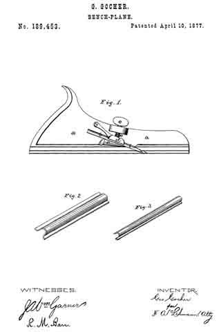
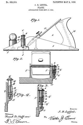
No. 820,215 – Plane (John D. Leffel) (1906)
UNITED STATES PATENT OFFICE.
_________________
JOHN D. LEFFEL, OF JOHNSTOWN, PENNSYLVANIA.
PLANE.
_________________
820,215. Specification of Letters Patent. Patented May 8, 1906.
Application filed September 17, 1904. Serial No. 224,842.
_________________
To all whom it may concern:
Be it known that I, JOHN D. LEFFEL, a citizen of the United States, residing at Johnstown, in the county of Cambria and State of Pennsylvania, have invented new and useful Improvements in Planes, of which the following is a specification.
This invention relates to planes designed especially for cutting out the back of molding to be used in constructing window and door casings, and has for its objects to produce a simple inexpensive device of this character in which the plane in making the first or initial cut in the back of the molding will be accurately guided longitudinally of the latter, to thereby prevent destroying the bearing edge of the molding.
To these ends the invention comprises the novel features of construction and combination of parts more fully hereinafter described.
ln the accompanying drawings, Figure 1 is a side elevation of a plane embodying the invention. Fig. 2 is a front view of the same, partly in section, illustrating the device in operation, the section being taken on the line 2 2 of Fig. 1. Fig. 3 is an enlarged detail section of the guiding member, showing the same in active position. Fig. 4 is a similar view showing the member in normal inactive position.
Referring to the drawings, 1 designates the body of the plane, having its lower bearing face or sole slightly curved transversely and provided with uprising side walls or flanges 2, upon one of which is fixed a tubular barrel or sleeve 3, adapted to receive a vertically-movable member or plunger 4, carrying at its lower end a guide plate or head 5, the inner vertical face of which travels smoothly over the outer face of the adjacent side flange 2. The plunger-rod or member 4, which is provided at its upper end with a head 6, is adapted to be pressed downward for maintaining the guide member 5 in active position by means of a spring 7, arranged within the barrel 3 and coiled upon the rod 4 between fixed collars or abutments 3′ 4′ , provided on the barrel and rod, respectively, and forming terminal bearings for the spring, whereby the latter in expanding will move the guide-head into action. The rod 4 further has a laterally-projecting stud or stop 8, adapted normally to engage the upper edge of the barrel 3 for maintaining the guide in normal elevated position, the stud being designed to travel in a vertical opening or slot 9, formed through the wall of the barrel when it is desired to depress the plunger for moving the guide to active position.
The plane is provided with the usual handle 10 and with a cutting-blade 11, the lower active edge of which is convexedly curved transversely, as shown in Fig. 2, whereby the plane in operation will form in the rear face of the molding shallow troughs or channels 12 for the usual purpose of reducing the contacting surface of the molding when employed in the construction of window and door frames.
In practice when the plane is initially brought into operation the plunger 4 is rotated until the pin 8 comes into register with slot 9, whereupon the spring 7 will act for automatically moving the plunger downward and projecting the guide member 5 below the plane of the lower face of the tool, as illustrated in Fig. 2, whereby during travel of the plane longitudinal of the molding the member 5 will bear upon the outer marginal edge of the latter, and thereby guide the plane in its movements and at the same time prevent the plane slipping and destroying the narrow bearing-face formed adjacent to the longitudinal edge of the molding. After formation of the first channel 12 adjacent the edge of the molding the plunger may, by grasping the head 6, be raised to bring the guard 5 to normal position, with its lower edge flush with that of the plane, and may be fixed in this position by a slight rotation of the plunger for moving the pin out of register with slot 9, as heretofore explained.
From the foregoing it is apparent that I produce a simple device admirably adapted for the attainment of the ends in view, it being understood that minor changes in the details herein set forth may be resorted to without departing from the spirit of the invention.
Having thus described the invention, what is claimed as new is —
1. The combination with a plane, of a tubular sleeve carried thereb and slotted longitudinally, a longitudinally-movable plunger mounted in the sleeve, a guide member carried by the plunger, a stud provided on the latter and adapted to engage the end edge of the sleeve for maintaining the plunger in normal retracted position, and a spring acting upon and to project the plunger for moving the guide member to active position, the stud being adapted during such movement of the plunger to travel in the slot.
2. The combination with a plane, of a guide member operatively connected therewith and adapted to normally lie in a plane above and to be projected below the sole of the plane for and to bear upon the side of a body for guiding the plane in its movements thereover, means for moving the guide member to active position, and means for locking the member in inactive position.
3. The combination with a plane, of a guide member operatively connected therewith and adapted to be projected below the sole of the plane in position to bear upon the side of the body for guiding the plane in its movement thereover, a spring for automatically moving the member to active projected position, and means for locking the member in normal, inactive position in a plane above the sole of the plane.
In testimony whereof I affix my signature in presence of two witnesses.
JOHN D. LEFFEL.
Witnesses:
J. S. WILMOT,
HERMAN OTT.