No. 65,562 – Improvement In Joiners’ Planes (Arthur Gray) (1867)
[paiddownloads id=”127″]65562


United States Patent Office.


ARTHUR GRAY, OF NAPLES, MAINE.

Letters Patent No. 65,562, dated June 11, 1867
_________________

IMPROVEMENT IN JOINERS’ PLANES.

_________________

The Schedule referred to in these Letters Patent and making part of the same.

_________________

TO ALL WHOM IT MAY OONCERN:

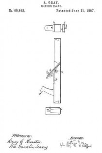
Be it known that I, ARTHUR GRAY, of Naples, in the county of Cumberland, and State of Maine, have invented a new and useful Improvement in Planes; and I hereby declare the following to be a full, clear, and exact description thereof, which will enable others to make and use my invention, reference being had to the accompanying drawings, forming part of this specification, in which —

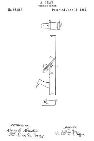
Figure 1 shows a side sectional elevation of a plane-stock with my improvement exhibited therein.

Figure 2 represents a front view of the baclcircn and the method of its attachment to the plane-stock.

Figure 3 represents a view of the clamping-iron with its staple.

Figure 4 is an end view of the same showing the thumb-screw.

My invention has relation to a new and more convenient method of securing the cutting-iron in an ordinary plane-stock.

a shows what I will term the back-iron, secured to the stock by the screw b, and having the projection c, which is somewhat within the aperture in the stock for the insertion of the cutter. Behind this projection is the small space d. e is the cutter, which is placed between the back-iron and the clamp h. The clamp holds the cutter as follows: k is a staple on the clamp, which staple passes under the projection c, as seen in the drawing. m is a thumb-screw. The cutter is placed on the back-iron a; over the cutter is then put the clamp h, with its staple k under the projection c; then turn the thumb-screw, and as the screw presses off the upper end of the clamp from the cutter it will bind the cutter at the lower end and be confined by the staple passing under the projection. Thus a simple arrangement is provided for holding the cutter. By turning out the screw the pressure of the clamp is relieved and the cutter can be removed or changed in position.

I do not claim the combination of an adjustable cap and a screw for the purpose of securing the bit, which bit is held by two screws, one on each side of the bit, as is exhibited in Letters Patent No. 10,748 to W. S. Loughborough, April 4, 1854. Neither do I claim the combination of a movable friction-plate-separate from the plane-iron, with the throat of the plane-stock, thc said plate being secured by a screw passing through it and the plane-iron, as seen in Patent No. 20,615, to L. Bailey, June 22, 1858.

I also disclaim one or more bearers, a clamp-lever, and a thumb-cam, as a means of fixing the plane-iron, adjusting the same in the stock, and removing it therefrom, seen in another patent to said Bailey, No. 21,311, August 31, 1858. Neither do I claim the combination of a cap and screw and two trunnions, fitting in adjustable bearings to hold the cutting-iron of a plane, as set forth in Letters Patent to Seth C. Howes, No. 37,694, February 17, 1863. These devices are different from mine in not having the clamp h, with its staple k, to operate in combination with the thumb-screw m and projection c on the bottom of the back-iron to confine the cutter.

What I claim as my invention, and desire to secure by Letters Patent, is —

The combination of the projection e, on the back-iron, with the staple k and thumb-screw m on the clamp, when arranged as and for the purpose set forth.

ARTHUR GRAY.

Witnesses:
WM. HENRY CLIFFORD,
HENRY C. HOUSTON.

No. 17,951 – Joiner’s Plane (Thomas D. Worrall) (1857)

[paiddownloads id=”50″]17951


UNITED STATES PATENT OFFICE.

_________________

THOS. D. WORRALL, OF LOWELL, MASSACHUSETTS.

JOINER’S PLANE.

_________________

Specification of Letters Patent No. 17,951, dated August 4, 1857.

_________________

To all whom it may concern:

Be it known that I, THOS. D. WORRALL, of Lowell, Massachusetts, have invented certain new and useful Improvements in Planes; and I do hereby declare that the following is a full, clear, and exact description of the same, reference being had to the accompanying drawings and to the letters of reference marked thereon.

The nature of my invention consists in certain devices for securing and regulating the bits in planes, the peculiarities of which will be hereinafter fully described.

In order that others skilled in the art may manufacture and use my invention I will proceed to describe its construction and operation.

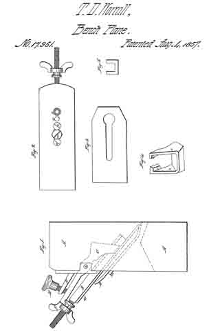
In the accompanying drawings which make a part of this specification Figure 1 is a side elevation showing its internal arrangement in dotted lin. Fig. 2 is a plan view of the bit. Fig. 3 is a view of the cap. Fig. 4 is a perspective view of the bottom of the clamp lever. Fig. 5 is a top view of said lever.

In Fig. 1 (A) is the body or stock of the plane. B is a strap attached to the back of the bit — having a screw in its upper extremity — its lower extremity being in the form of a T. (G) is the bit secured to the T strap by means of screws (n n’) seen in Fig. 2. H is the cap having a slot in it as seen in Fig. 3, and secured to the bit by means of a screw (m), said cap being concave as seen in Fig. 1. (D) is a rest attached to the top of the plane. (C) is a clamp lever, being pivoted at (i) and having a slot in its upper extremity (o) seen in this figure being one of the arms of said slot. (F) is a nut, working on the screw on the end of T strap (B), said nut having a groove in it, the groove fitting in the slot on the end of lever C. (E) is a screw passing through rest (D) and serving to operate lever (C).

Fig. 2 represents the bit, (n, n) being screws through it for the purpose of adjusting the T strap, as the plane bit wears. As the bit wears away the screws (n’ and n) may be removed; also, screws (m). Then after slipping the bit down (n’) will enter the place occupied by (n). (n) will occupy hole (x) and m will occupy the hole (n). In this manner I may use a suflicient number of holes and wear the bit entirely up, which cannot be done in the ordinary plane secured with strap.

Fig. 4 shows the bottom of clamp lever C — the T arms of lever C slip in between jaws (a) and slide on flanges (c), being clamped by said flanges when the lever is operated above by means of screw (E).

Fig. 5 shows a top view of the clamp lever with its slot for receiving the tap or nut (F).

In operating this plane the bit is first secured to the T strap, then the cap may be adjusted to its proper position on the bit, and the strap inserted into position in the plane stock — the lower extremity of the T strap enters the jaws of clamp lever C and its arms slide on, and are secured by flanges (c) — the groove in nut (F) being adjusted in slot into top of lever C the screw (E) is operated and the bit firmly secured.

The advantages of clamp lever C are very readily perceived (the lever may be made any desired or convenient length and the power obtained by it may be very great) for there is no known process by which a plane bit may be so securely bedded as by this — this lever operates upon the bit at two important points for bedding it — it draws the bit in at the bottom, with the power, and in a manner that can be done by no other means. The easy adjustment of the plane by means of lever C and screw (E) gives it advantages not possessed by other planes.

Having thus fully described my invention what I claim as new and desire to secure by Letters Patent is —

I claim —

The employment of the clamp lever C for securing and bedding the bit, in the manner herein fully set forth and described.

In testimony whereof I hereunto set my hand.

THOS. D. WORRALL.

Witnesses:
C. M. ALEXANDER,
JOHNS HOLLINGSHEAD.

No. 18,312 – Attaching Adjustable Handles To Joiner’s Planes (Thomas D. Worrall) (1857)

[paiddownloads id=”68″]18312


UNITED STATES PATENT OFFICE.

_________________

THOS. D. WORRALL, OF LOWELL, MASSACHUSETTS.

METHOD OF ATTACHING ADJUSTABLE HANDLES TO JOINERS’ PLANES.

_________________

Specification of Letters Patent No. 18,312, dated September 29, 1857.

_________________

To all whom it may concern:

Be it known that I, THOS. D. WORRALL, of Lowell, Massachusetts, have invented certain new and useful Improvements in Movable and Adjustable Handles for Molding-Planes; and I do hereby declare that the following is a full, clear, and exact description of the same, reference being had to the accompanying drawings and to the letters of reference marked thereon.

The nature of my invention consists in certain devices for attaching and adjusting the handles on molding planes, the peculiarities of which will be hereinafter described.

In order that others skilled in the art may manufacture and use my invention I will proceed to describe its construction and operation.

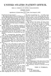
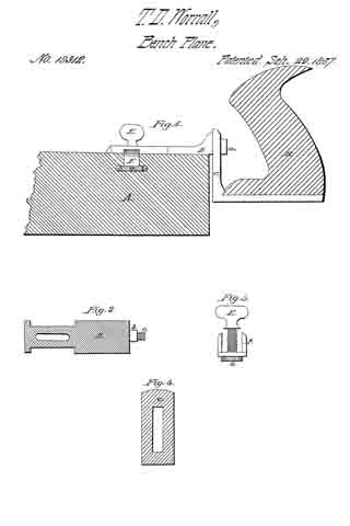
In the accompanying drawings which make a part of this specification Figure 1 is a side elevation. Fig. 2 is a plan view of plate, D, Fig. 1. Fig. 3 is a view showing the slotted face of rectangular strap C. Fig. 4 is view of the nut, button and screw, for attaching plate D to the stock or wood part of the plane.

In Fig. 1 A is the stock or body of the plane, (B), is the handle, (D), is a slotted cap plate, resting on the top of the plane as seen in this figure. (C), is a rectangular strap of metal, the handle (D), being attached to one arm, the other extending several inches in front of the handle, is slotted, as seen in Fig. 4. (F), is a nut, with jaws as seen in Fig. 3. (G), is a button on the back of nut (F). (E), is a thumb screw passing through plate (D), and entering nut (F) as seen in Fig. 3.

Fig. 2 represents the slotted plate (D), (B), is a square shaft, passing through slot in strap C, (c), is a screw on the end of shaft b. Nut (a) in Fig. 1 passes over this screw and attaches plate (D), to strap (C).

In attaching this handle to planes, I first cut a groove in the top of the plane and a mortise in the side, the groove and mortise meeting form a T-shaped slot. The nut, F, fits in the body of this slot and the flanges formed by the projecting of the button beyond the sides of the nut fit in the arms of the slot. Plate D fits on top of the plane, between the arms, or jaws of nut, F, and over the slot, screw, E, passes through the slot in cap plate, D, and enters the nut, F, and secures the handle firmly to the plane. By means of the slot in cap plate D, the handle may be made to assume the position seen in Fig. 1 or strap, C, may lit up snugly against the plane as is the general manner of using it.

Strap C it will be seen is slotted for the purpose of adjusting the handle, elevating or lowering it as circumstances or convenience may require; the handle when placed at any desired position may be secured by means of the nut, (a). This adaptation of the handle to the top or bottom of the plane is particularly desirable in some instances. If the bit is set for cutting a very thin shaving the handle may be at the top or above the top of the plane, but if set for cutting a heavy shaving the handle should be as low as possible in order to have the power in a line with the work, so that the plane will not tilt but move steadily.

One of the chief advantages of my movable handle is that it does away with the necessity of making handle to my planes. They may thereby be aiforded at a much cheaper rate. This handle is so easily adjusted on the plane that but little time will be consumed in changing from one to the other.

Having thus fully described my invention what I claim as new and desire to secure by Letters Patent is —

1. I claim the combination and arrangement of cap plate D, screw E, nut F, and T slot o, in the plane for the purpose of providing and securing a movable handle to planes.

2. I claim the arrangement of cap plate D, slotted strap C, and screw a, for the purpose of adjusting the handle vertically when desired by the operator as set forth and described.

THOS. D. WORRALL.

Witnesses:
C. M. ALEXANDER,
JOHN S. HOLLINGSHEAD.

No. 16,569 – Joiner’s Plane (J.F. Palmer) (1857)

[paiddownloads id=”36″]16569


UNITED STATES PATENT OFFICE.

_________________

J. F. PALMER, OF AUBURN, NEW YORK, ASSIGNOR TO S. W. PALMER, OF DETROIT, MICHIGAN.

JOINER’S PLANE.

_________________

Specification of Letters Patent No. 16,569, dated February 3, 1857.

_________________

To all whom it may concern:

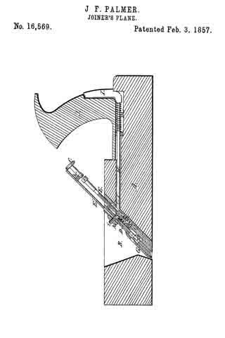
Be it known that I, J. F. PALMER, of Auburn, in the county of Cayuga and State of New York, have invented a. new and useful Improvement in Joiners’ Planes; and I do hereby declare that the following is a full, clear, and exact description of the same, reference being had to the annexed drawing, making a part of this specification, said drawing being a longitudinal vertical section of my improvement.

My invention consists in the peculiar means employed for adjusting the plane iron, as will be hereinafter fully shown and described, whereby the plane iron may be set with the greatest facility and also be raised free from the work as the plane is drawn back so that the cutting edge of the iron is not impaired thereby.

To enable those skilled in the art to fully understand and construct my invention, I will proceed to describe it.

A represents the plane stock which is constructed of wood and in the usual manner. B is the opening or throat in the plane, and C is a metal plate which is screwed to the back side of the opening or throat, the lower edge of the said plate being beveled and made flush with the bottom or face of the stock. The upper end of the plate is also flush with the upper surface of the stock. The plate C has an oblong recess (a) made in it to receive a spiral spring (b) and also has four guide slots made in it to receive pins (d) which are attached to the back of a plate D which is fitted over the plate C, the plate D being a trifle shorter than the plate C. The plate D has a projection or lip (e) on its back side, said projection or lip fitting over the spring (b) in the recess (a) of the plate C. The projection or lip (e) is notched, or it may be formed of two parts to allow a screw rod E to pass through it. The upper end of the screw rod has a small thumb wheel (f) upon it, and a groove or recess (g) is made circumferentially in the upper part of said rod to receive a fork (h) which is attached to the back side of the plane iron E’. The lower part of the screw rod has a nut F upon it which leans upon the projection or lip (e) on the plate D, and this nut has a screw (i)attached to it, said screw passing through a hole (j) in the plate D, and through a slot (j’) in the plane iron E’, and having a thumb nut (k) on its outer end. The lower part of the plane iron E’ has a cover iron G attached to it.

The upper edge of the nut F is beveled as plainly shown in the drawing, and a rod H is fitted longitudinally in the stock A, said rod having a vertical plate I attached to its back end, the plate I being at the back side of the tote or handle J. The front end of the rod H has a fork (l) formed on it, and when the rod H is pressed forward, it passes through an opening in the plate C and bears upon the upper nut F — a spiral spring (m) is placed upon the rod H, said spring keeping the fork free from the nut F.

From the above description will be seen that by turning the screw rod E, the plane iron E’ may be raised or lowered so as to give it the required “set,” and the plane iron is firmly secured in position or prevented from turning casually. The plate D is connected with the plate C by a guide pin so as to regulate the length of vibration of the plate D and plane iron E’, which are forced downward as the plane is shoved forward by pressing the palm of the hand against the plate I, the rod H being shoved forward thereby and the fork (l) bearing or pressing down the nut F, and consequently the plate D and plane iron E’, said plate and plane iron being kept up above the work or board being planed by means of the spring (b).

By the above improvement the plane iron may not only be set with facility but it is kept up from the work as the plane is drawn backward and consequently the cutting edge of the iron E’ is prevented from being rounded and rendered dull. The plane irons of ordinary planes are soon deprived of their sharp edges in consequence of being drawn backward over the work.

Having thus described my invention, what I claim as new and desire to secure by Letters Patent, is,

The two plates C, D, and plane iron E’ arranged relatively with each other as shown and used in connection with the screw rod E, and rod H as herein described and for purpose set forth.

J. F. PALMER.

Witnesses:
HORACE T. COOK,
C. H. JENKIN.

No. 5,620 – Joiner’s Plane (William A. Cole) (1848)

[paiddownloads id=”22″]5620


UNITED STATES PATENT OFFICE.

_________________

WILLIAM A. COLE, OF NEW YORK, N. Y.

JOINER’S PLANE.

_________________

Specification of Letters Patent No. 13,957, dated December 18, 1855.

_________________

To all whom it may concern:

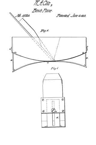
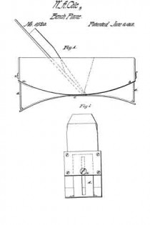
Be it known that I, WILLIAM A. COLE, of New York, in the county of New York and State of New York, have invented a new and Improved Plane for Planing Curve or Level Surfaces; and I do hereby declare the following to be a full, clear, and exact description of the same, reference being had to the annexed drawings, making a part of this specification, in which —

Figure 1 is a side elevation of the plane. Fig. 2 is an end view.

Similar letters refer to similar parts, in both figures.

The nature of my invention, consists in an improvement in the construction of the plane, by which I am enabled to curve the face of the plane either concave or convex, and regulate the face of the said plane so as to plane various curves with the same plane.

In making my improvements I take an ordinary plane, with the plane irons, &c., as usual, I then cut a convex face upon it as seen at (a–b). To the face thus prepared I attach a plate of metal (c), at the center, the length and width of the plane; at the center there is a slot cut across through which the edge of the cutting iron may pass. At each end of the plate (c) there is a slide (d) connected, which passes up against the front and back of the plane, beneath a plate of brass, space being left sufficient to allow it to pass up and down.

In operating this plane, the face plate (c) is set to the desired curve, by pushing the pieces (d) down, these are then confined in their places, by a screw (e) upon the ends of the plane as represented. It will be seen that concave and convex surfaces can be planed by this instrument, and that it can be adjusted to any desired curve, as set forth and described above.

What I claim as my invention and improvement, and desire to secure by Letters Patent, is —

The adjustable metallic spring plate, secured to the face of the plane for the purpose of planing with one plane, various curves either concave or convex, substantially as herein described and set forth.

WM. A. COLE.

Witnesses:
A. W. KELLOGG,
I. P. PIRSSON.

No. 5,486 – Joiner’s Plane (Benjamin F. Shelabarger) (1848)

[paiddownloads id=”21″]5486


UNITED STATES PATENT OFFICE.

_________________

BENJ. F. SHELABARGER, OF MIFFLINTOWN, PENNSYLVANIA.

JOINER’S PLANE

_________________

Specification of Letters Patent No. 5,486, dated March 28, 1848.

_________________

To all whom it may concern:

Be it known that I, BENJ. F. SHELABARGER, of Mifflintown, in the county of Juniata and State of Pennsylvania, have invented a new and useful Improvement in Planes for Working Lumber ; and I do hereby declare the following to be a full, clear, and exact description thereof, reference being had to the accompanying drawings, making a part of this specification.

The nature of my invention consists in combining an adjustable metallic throat piece, with a plane iron and stock, in such a manner that the discharging aperture for the shavings will not be rendered imperfect or enlarged by the wearing away of the plane stock.

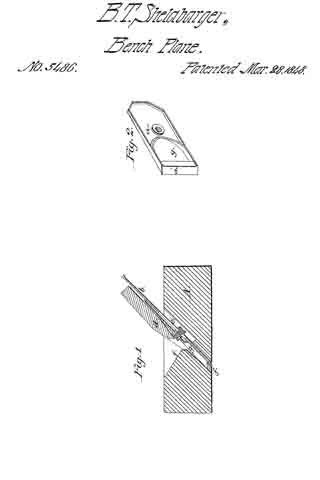
In the accompanying drawings Figure 1, is a vertical longitudinal section of a plane having my improved adjustable throat piece, combined with the same, and Fig. 2, is a perspective view of the throat piece detached.

A, is the plane stock.
a is the adjustable throat piece.
b, is the plane iron.
c, is a set screw, securing the plane iron to the throat piece.
e, is a slot in the plane iron, through which the screw c, passes.
d, is the tightening wedge, which secures the plane iron and throat piece within the plane stock.

The throat piece has a bearing surface a’ at its lower end, between which and the front side of the plane iron there is a space for the shavings to pass between, and out through the aperture g, in the throat piece, into the enlarged discharging throat f, in the plane stock. The enlarged discharging throat f, descends to about one half the depth of the stock; from the bottom of this enlarged throat, there is carried down to the base of the plane, a mortise with parallel sides, just large enough to receive the adjustable throat piece with the plane iron attached to it. It will readily be perceived therefore, that the bearing surface of the throat piece in front of the cutting edge of the plane iron, can be adjusted, as the stock wears away, so as to be always on a line with the face of the plane stock. The aperture between the bearing surface a’, of the throat piece, and the plane iron, — for the passage of shavings, — will remain perfect and of the same size till the plane stock is worn out; when the throat piece may be placed in a new stock. The advantage of having a perfect shaped discharging aperture in planes for the escape of the shavings, is so apparent, and so well known by all who are familiar with the use of this tool, that it is not necessary to dwell upon the subject. With planes, as now constructed, the discharging aperture for shavings, immediately in front of the plane irons, is constantly increasing in size, by the wearing away of the base of the plane stock. My adjustable metallic throat piece perfectly obviates this difliculty. My adjustable throat pieces I intend to apply to planes of all shapes and descriptions; the bearing surface of the throat piece, in all cases to correspond with the face of the planes. The aperture g, in the throat piece, extends upward a suflicient distance to allow the shavings to escape freely into the space.

What I claim as my invention and desire to secure by Letters Patent, is —

The combination of an adjustable metallic throat piece, with the irons and stocks of planes of all descriptions, substantially in the manner and for the purpose herein set forth.

BENJAMIN F. SHELABARGER.

Witnesses:
R. BARNARD,
SAML. C. FORREY.

No. 17,286 – Joiner’s Plane (Benjamin I. Lane) (1857)

[paiddownloads id=”41″]17286


UNITED STATES PATENT OFFICE.

_________________

BENJAMIN I. LANE, OF NEWBURYPORT, MASSACHUSETTS.

JOINER’S PLANE.

_________________

Specification of Letters Patent No. 17,286, dated May 12, 1857.

_________________

To all whom it may concern:

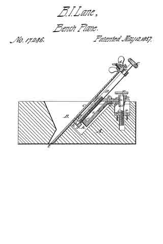
Be it known that I, BENJAMIN I. LANE, of Newburyport, in the county of Essex and State of Massachusetts, have invented a new and useful Improvement in Joiners’ Planes; and I do hereby declare that the following is a full, clear, and exact description of the same, reference being had to the annexed drawing, making a part of this specification, said drawing being a longitudinal vertical section of a plane with my improvement applied to it.

This invention consists in a novel means employed for securing the iron properly within the plane, and also for adjusting said iron, and giving it more or less “set” as may be desired.

To enable those skilled in the art to fully understand and construct my invention, I will proceed to describe it.

A, represents the body or stock of the plane constructed of wood and in the usual way.

B, is the throat of the usual form; and C, is the iron placed within the throat; the back of the iron resting or bearing against the back edge or side of the throat. To the back side of the iron C, near its lower end, a ledge (a), is secured, and a slot (b), is formed or made in its upper end. A ledge or small bar (c), is placed in the slot (b),
and is secured therein by a thumb nut (d), which is fitted on a screw (e), which passes through the slot (b).

D, is a screw rod, the lower end of which is stepped in the ledge (a) ; the upper end of the rod passes through the ledge or bar (c), and has a thumb wheel (f), on it.

E, represents a metal plate which is fitted on a plate F, secured and “let in” flush with the upper surface of the stock A. The plate E, is secured to the plate F, by screws (g), which pass through slots in the plate E. The plate E, therefore, is allowed a certain degree of play on the plate F. The screw rod D, passes through a hole (i), in the inner end. of the plate E; and also through a hole (j), in a bar or projection (k), at the lower end of a bar (l). This bar (l), is attached to the under side of the plate E; and a screw thread is out in the hole (j) through which the screw rod passes. In the back part of the plate E, a square opening (m), is made, and a wedge (n), is fitted therein. This wedge (n) , has a rod (o), passing vertically through it; the lower part of the rod having a screw thread formed on it; the screw portion passing through a nut (p), secured in a recess (g), in the stock A. The upper end of the rod (o), has a thumb wheel (r), on it.

The back side of the throat B, on which the iron C, rests has a recess (s), made in it, to receive the bar (l), and allow it a requisite degree of play.

From the above description of parts it will be seen that the iron C, may be raised and lowered by turning the screw rod D, so that the cutting edge (t), may have the required “set”; and the iron is firmly bedded or made to bear snugly against the back side of the throat B, by turning the rod (o); whereby the wedge (n), is depressed, the plate E, forced outward, and iron pressed or drawn firmly against the the back side of the throat.

I do not claim separately the screw rod D, for raising and lowering the iron C, for that has been previously used for effecting the same purpose; — but,

Having thus described my invention, what I claim as new, and desire to secure by Letters Patent, is:

1. The sliding plate E, with bar (l), attached, through which the screw rod D, passes; the plate E being operated by the wedge (n), and screw rod (o); substantially as described, for the purpose set forth.

2. I also claim, in cornbination with the plate E, and bar (l), arranged and operated as shown, the screw rod D, applied to the iron C, and connected with the plate E, and bar (l), as described, whereby the iron C, may be adjusted or “set” with facility, and also secured firmly in proper position within the plane.

BENJ. I. LANE.

Witnesses:
JAMES F. BUCKLEY,
WM. TUSCH.

No. 17,332 – Joiner’s Plane (James Lashbrooks) (1857)

[paiddownloads id=”42″]17332


UNITED STATES PATENT OFFICE.

_________________

JAMES LASHBROOKS, OF OWENSBORO, KENTUCKY.

JOINER’S PLANE.

_________________

Specification of Letters Patent No. 17,332, dated May 19, 1857.

_________________

To all whom it may concern:

Be it known that I, JAMES LASHBROOKS, of Owensboro, in the county of Daviess and State of Kentucky, have invented certain new and useful Irnprovernents in Hand-Planes; and I do hereby declare that the following is a full, clear, and exact description thereof, reference being had to the accompanying drawings and to the letters of reference marked thereon.

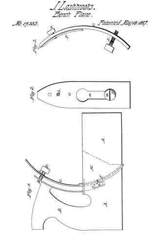
The nature of nay invention consists in the use of a curved bit whereby I am enabled to use a handle on all planes however short without any inconvenience.

In order that those skilled in the art may use and manufacture my invention I will proceed to describe operation and construction. In the accompanying drawings which make a part of this specification Figure 1 is a side elevation. Fig. 2 is a plan view of the bit. Fig. 3 is a side elevation of the bit.

In Fig. 1 A is the stock, B the handle, C the bit, D a plate of steel extending into the stock and attached to the handle. L is a screw passing through the bit C for the purpose of holding in its position, E the head of said screw. G seen in dotted line shows a screw for attaching bit F to bit C. g is a slot in the stock in which screw G works.

In Fig. 2 C is the bit, L the screw, a a slot through which screw G passes attaching the two bits.

In Fig. 3 C the main bit, F the cap bit, G screw for attaching them, L screw for stationing the bits at any desired point.

In the operation of my invention the bit and cap are first fastened together by means of the screw G and adjusted to the position required in the stock and then set to the depth required for planing by ineans of screw L which presses against plate D, D. The plane is then ready for use. It will be seen that as the bit C is pressed by means of screw L against plate D the effect of the leverage is to press the lower end of the bit firmly against the lower side of the plane stock through which it passes thus making a more solid and firm plane than by any other device known, doing away entirely with wedges in my curved bit plane.

One of the peculiar advantages of my invention consists in causing the bit to curve forward and thus allowing me room to set a handle on all short or smoothing planes which cannot be done by any other shaped bit heretofore known and which object is of great iinportance in short planes. It is also applicable to all planes.

Having thus described my invention what I claim is —

The curved plane iron C and cap F in combination with the curved back rest and slotted plate D operating as described and for the purpose set forth.

JAMES L ASHBROOKS.

Witnesses:
HENRY DUGAN,
JOHN LASHBROOK.