
No. 379,940 – Block-Rabbet Plane (Joseph Doray) (1888)

UNITED STATES PATENT OFFICE.
_________________
JOSEPH DORAY, OF WORCESTER, MASSACHUSETTS.
BLOCK-RABBET PLANE.
_________________
SPECIFICATION forming part of Letters Patent No. 379,940, dated March 27, 1888.
Application filed August 15, 1887. Serial No. 247,032. (No model.)
_________________
To all whom it may concern:
Be it known that I, JOSEPH DORAY, of the city and county of Worcester, and Commonwealth of Massachusetts, have invented a new and useful Block-Rabbet; and I do hereby-declare that the following is a full description of the same, reference being had to the accompanying drawings, and the letters of reference marked thereon, forming a part of this specification, and in which —
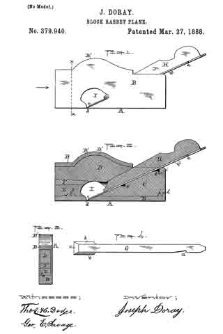
Figure 1 represents a side view of my said block-rabbet ready for use. Fig. 2 represents a longitudinal vertical central section of the device and the parts of which it is composed, except the knife or cutter, which is not shown in section. Fig. 3 represents a cross-section on line x x, Fig. 1, looking in the direction indicated by the arrow, Fig. 1; and Fig. 4 represents a top or plan view of the knife or cutter detached, as will be hereinafter more fully described and explained.
To enable those skilled in the art to which my invention belongs to make and use the same, l will now describe the invention more in detail.
In the drawings, A represents the complete device ready for use. The part marked B represents the metal shell or case, and is made in a peculiar manner. The right-hand end of the device is made with an opening to permit the right-hand end of the part C to project out flush with the outer surface of the end of the shell B, while the shoulders j and k of the part C rest or abut against the shoulders h and i of the shell B, all as fully shown in Fig. 2. The upper left-hand end of the filling-piece C is made with an inclined or wedge-shaped surface to receive and support the rear part of the cutting end of the knife and its shank end, as fully indicated in the drawings.
The wooden filling-piece D is made inclined up or wedge-shaped on its under side (right-hand end) to iit against and hold the wedge or holding-piece H, while its upper edge (right-hand end) is made in curved form, as shown at D’, to fit the inner upper curved part, B’, of the shell B. The under surface of the left-hand end is inclined up or in wedge shape as it extends back from the middle of said piece. The wooden filling-piece E is made, in this instance, with a notch, f to fit over the projection e on the inner surface of the bottom of the left-hand end of the shell B, while the upper surface of the filling-piece E is inclined down or in wedge shape from its inner to its outer end.
Between the left-hand ends of the wooden filling-pieces C and D is inserted wedge-piece F.
For the convenience of the constructor or user in putting the part C in place, a notch, g, is made in the upper inclined edge of the part C to receive the end of a forcing stick. In the proper and best use of the tool the slot or slit d should extend from side to side, so that the cutting end c will be as wide as the shell or case is thick, and to enable the operator to insert the cutter or knife G, the space between the parts C and D is great enough to let the knife run down when turned up edgewise at an angle of about thirty degrees until it reaches the opening I, in which it can be turned down into place and fastened by the holding-wedge H. By this mode of construction the opening or slit d can be made quite narrow, just wide enough to let the edge of the knife through and allow the passage of a very thin shaving.
By making the knife or cutter G thin and flat, as shown, excepting the parts provided with the bevels b b and c, the device is rendered light, while at the same time, where it is clamped by the holding-wedge H, being flat and thin, it readily yields to the pressure of said wedge and conforms to the surfaces between which it is clamped, and is thus clamped and securely held in position. Then, again, by making the lower end thick and providing it with bevels b b on its sides a cutting-edge, c, can be obtained, which, when the cutter is in position, as shown in Figs. 1 and 2, will cut the full width of the metal shell or case, and which cutting end is held firmly to its work by the end of the holding-wedge H bearing and wedging thereon, as also shown in Figs. 1 and 2 of the drawings, while by the notch a the cutter can be drawn back and adjusted after the holding-wedge H has been loosened. It will thus be seen that the outer thin flat end of the cutter will readily bend or yield, and will be caught, clamped, and firmly held at some point back of the point where the lower end of the holding-wedge rests upon the lower thin flat end of the cutter, and that, too, without any undue straining of the parts.
The piece of wood filling C is first run into place, then the wood filling-piece D is inserted, then the piece E, and then the wedge-piece F is driven in, thereby fastening the parts C, D, E, and F securely in position in the shell or case B, which, as before stated, is made of metal. In practice I prefer to apply glue to the sides and edges of the wedge-holding piece F before it is driven in, thereby rendering the parts D, E, and F as firm as if made of a single piece. A single piece, it will be noticed, could not be inserted.
If preferred in any case, the wedge F may be dispensed with, also the notch f and projection e, and the piece E made to wedge with the piece D, and if glued before being driven in will be fastened to the part D, the curved projection D’ preventing the parts from moving either forward or back. I prefer, however, to make the parts as shown inthe drawings.
The shell or case B, it will be noticed, is made and adapted for this tool, and the same is true of the knife or cutter, neither of which is suitable for usein any other tool. By my mode of construction the tool can be made very cheap, and so strong are all the parts united that one will last a man’s life-time.
Those skilled in the art will readily understand and appreciate the great practical value and utility of my said invention. The tool can be made small, even small enough to be carried in the pocket, and thus be ever at hand for use. This tool takes the place of a chisel in finishing the corners of rabbets, repairing beadings, and like work, while the work can be done much quicker and more perfectly than in the ordinary manner, and when the great amount of this work required in finishing good articles and buildings is considered the saving in time and expense by the use of my said invention, even in the hands of a single work man, is large.
Having described my newly-invented block-rabbet, what I claim as my invention, and desire to secure by Letters Patent, is —
1. The combination, with the metal shell or case B, of the wood filling or parts C, D, and E, knife G, and holding-wedge H, as shown and described, and for the purposes set forth.
2. The combination, with shell or case B, provided with the projection e, of the wooden filling-piece E, having the notch j, to receive the projection e, as and for the purposes set forth.
3. The combination, with the metal shell or case B, made as described, of the wooden filling pieces C, D, and E and wooden wedge-piece F, substantially as shown and described, and for the purposes set forth.
4. The knife or cutter G for a block-rabbet, having a thin flat end with a notch, a, and a thick cutting end with top beveled edges b b and c, as described and shown, and for the purposes stated.
5. A metal shell or case, B, for a block-rabbet, provided with lips or shoulders h and i, projection e, opening I, and narrow slit d, all as shown and described, and for the purposes stated.
JOSEPH DORAY.
Witnesses:
THOS. H. DODGE,
GEO. E. SAVAGE.