No. 135,341 – Improvement In Planes For Scraping (Joseph Jones) (1873)

[paiddownloads id=”207″]135341


UNITED STATES PATENT OFFICE.

_________________

JOSEPH JONES, OF NEWARK, NEW JERSEY, ASSIGNOR TO
WILLIAM A. FREEMAN, OF SAME PLACE.

IMPROVEMENT IN PLANES FOR SCRAPING.

_________________

Specification forming part of Letters Patent No. 135,341, dated January 28, 1873.

_________________

To all whom it may concern:

Be it known that I, JOSEPH JONES, of Newark, in the county of Essex and State of New Jersey, have invented an Improvement in Scraping-Planes, of Which the following is a specification:

This invention relates to that class of implements used in smoothing the surface of hard wood and other hard material, known as scraping-planes; and it consists in the combination, with the holder which carries the scraping-tool and with suitable slotted supports arranged at the sides of the stock, of a transverse bolt and a locking-nut, in such manner that the scraping-tool may be adjusted at any angle required in the work to which the implement is applied.

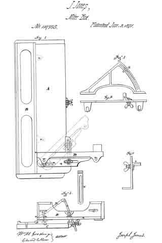
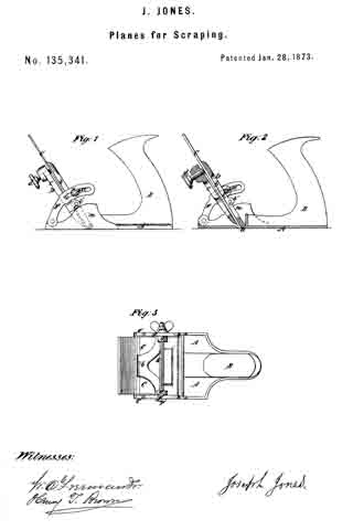
Figure 1 is a side view of an implement made according to my invention. Fig. 2 is a vertical longitudinal section of the same. Fig. 3 is a plan view of the same.

A is the stock, made of metal, and, in the main, in the ordinary manner, and provided with the handle B, whereby the requisite reciprocating movement is given to the implement when in use, and also with the upwardly-projecting cheeks m at the sides. At a, is the throat through which project the lower or scraping edges of the plane-iron C, this iron C being confined in the holder D. The holder is composed of two parts, b c, the former of which is pivoted by the lateral bearings at its lower end in close proximity to the throat a, as indicated in dotted outline in Fig. 1, and also shown in Fig. 2. The part c is attached by lugs b’ and pivots c’ to the part b, and carries at its upper end the screw d. By placing the iron C between the two parts and tightening the screw d, the iron is, of course, firmly clamped in place in the said holder. At each lateral edge of the part b of the holder is a lug or ear, g, and arranged in due relation thereto is a bar or support, F, pivoted, as shown at e’, to that end of the stock opposite the handle, and formed at its upper part with a longitudinal slot, a’, of a curvature which, when the supports are in position, as herein presently described, is on an arc more or less concentric with the pivoted point near the throat a of the holder. A transverse bolt, G, having a head, r, at one end and a nut, r’, at the other, is passed through the slots a’ of the supports just mentioned, and also through holes formed in the lugs g of the holder, in such manner that, by tightening the nut r’, the frictional hold of the head and nut of the bolt G upon the supports F will rigidly retain the same in a fixed position, and thereby insure the retention of the holder and its contained scraping-tool at any angle to which it may be adjusted. The degree of adjustment is, of course, limited only by the length of the slots in the supports F, Which latter serve to brace and sustain the tool against the strain exerted when the same is in use. Instead of having the supports pivoted, as hereinbefore described, the same may be constituted in one with the cheeks m — the latter being extended upvvard to a sufficient height, and provided With arc-shaped slots answering to those of the pivoted supports F, and for the same purpose.

What I claim as my invention is —

The combination, With the holder D having lugs g, of the slotted supports F pivoted to the stock A and the tightening-bolt G, the whole arranged and operating substantially as and for the purpose herein set forth.

JOSEPH JONES.

Witnesses:
HERBERT COTTRELL,
I. M. TAYLOR.

No. 110,765 – Improvement In Carpenters Shooting-Boards (Joseph Jones) (1871)

[paiddownloads id=”177″]110765


United States Patent Office.


JOSEPH JONES, OF NEWARK, NEW JERSEY.

Letters Patent No. 110,765, dated January 3, 1871.
_________________

IMPROVEMENT IN CARPENTERS’ SHOOTING-BOARDS.

_________________

The Schedule referred to in these Letters Patent and making part of the same.

_________________

I, JOSEPH JONES, of the city of Newark, in the county of Essex and State of New Jersey, have invented certain Improvements in the Carpenter’s Shooting-Board secured to me by Letters Patent, No. 52,719, issued February 20, 1866, of which improvements the following is a specification.

The first improvement relates to the bed-piece upon which the piece of wood lies to be planed;
The second relates to the stop and to its adjustment ; and
The third to an addition to the stop.

Figure 1 is a plan of the bed-piece, showing the improvements in both bed-piece and stop;
Figure 2 is an end view of the same;
Figure 3 is the additional attachment to the stop;
Figure 4 is a top view; and
Figure 5 is an end view of the same.

A is the bed-piece, which, from the end y to the stop, is a separate piece from the main frame;
B is the main frame;
C is the base-board; and
D, the stop.

In providing for the elevation of the bed-piece A, it is essential that its upper edge, next to the face of the plane, should be the center of motion, remaining close to the face of the plane, while the lower edge recedes therefrom, as the bed-piece is turned up to a required angle. To this end two rods, X, each a segment of a circle, whose center is at z on the upper edge-line of the bed-piece, are attached to and form part of the bed-piece A, and move in guides in the main frame B.

Upon the edge of the base-board C is a hinged screw-bolt, V; and to the back edge of the bed-piece there is attached a slotted bar, W.

The hinged bolt V goes through the slot in the bar W, and the bar is held in position by the thumb-nut n, securing the bed-piece A at any required angle of inclination.

The frame B has, from the end of the bed-piece A, at z, its upper face level with the bed-piece, when that bed-piece lies flat on the frame, upon which level face the stop D is secured.

t and u (the latter shown by dotted lines in fig. 1) show two slots in the level face, placed at right angles to each other.

A pin, r, passes through the slot u and the foot-piece q of the stop D, and a bolt, with a thumb-screw or nut, s, also passes through the foot-piece q and through a slot, t, in the frame, by which the stop is made easily adjustable to any required angle, and is held securely in place on the frame.

As an additional support to long stuff when having a bevel planed on its end, the frame, fig. 3, is made conveniently attachable to and detachable from the stop D.

In the outer bar of that frame is a semicircular slot, which is a segment of a circle, whose center is z on the main frame.

A projecting support, k, held by a thumb-screw, is by those means adjustable, as may be required, to any desired inclination.

Thus, having described my improvements, What I claim and desire to secure by Letters Patent, is —

The bed-plate B and adjustable table A, in combination with the stop D, all the parts being constructed, arranged, and operating in the manner and for the purpose as shown and described.

JOSEPH JONES.

Witnesses:
WM. M. GOODING,
EDWARD COLLVER.

No. 52,719 – Improvement In Carpenter’s Shooting Boards (Joseph Jones) (1866)

[paiddownloads id=”114″]52719


UNITED STATES PATENT OFFICE.

_________________

JOSEPH JONES, OF NEWARK, NEW JERSEY.

IMPROVEMENT IN CARPENTERS’ SHOOTING-BOARDS.

_________________

Specification forming part of Letters Patent No. 52,719, dated February 20, 1866.

_________________

To all whom it may concern:

Be it known that I, JOSEPH JONES, of the city of Newark, in the county of Essex and State of New Jersey, have invented certain Improvements in the Implement technically termed by workers in wood a “Shooting-Board” and I do hereby declare the following to be a full and exact description of the same, reference being herein had to the drawings accompanying this specification, making part of the same.

The nature of my improvement consists in attachments which adapt the board to the shooting or planing at any required angle in the direction required by the grain of the wood, and in securing the plane to the board in a way to ease its motion, at the same time rendering it more stable or solid at its work.

In the drawings, Figure 1 shows the board and the plane as when ready for use. Fig. 2 represents the end of the plane with the peculiarly – formed attachment thereto. Fig. 3 shows the bed-piece to which the plane is connected, with the providings for holding the plane securely thereto; also is shown an end view of the bed-piece and an end view of the shooting – board, Fig. 1. Fig. 4 shows the various parts used in the construction of the stop against which the piece to be planed is held.

The base-board, as is usual, has the part A elevated above the part B, the difference being increased in my improvement to admit under the plane C the bed-piece D, Fig. 3, the edge z of the bed-piece D being fitted to and sliding in the groove y in the edge of the elevated part A of the base-board.

The groove is shown in the end view of the base-board, Fig. 3.

The edge x has a projection, u, on the under side, as shown in the end view in Fig. 3, which slides in the V-shaped groove t. (Seen in the end view of the base-board at Fig. 3.)

On each end of the plane C is affixed a projecting piece, s, Fig. 2, which, when the plane is placed in the bed-piece D, is between the ends of the set-screws r, by which the plane is held down firmly to the bed-piece. The piece s being wider at the bottom than at the top, every turn of the screws r tends to pressing the plane close down to the bed-piece D, the set-screws being attached to the bed-piece by their nuts being formed in the projections p on the bed-piece D.

When necessary varied inclinations of the face of the plane C can be had by inclined bed-pieces, and the same result is attainable by the use of beveled pieces laid on the base-board under the piece to be planed.

The stop against which the board is placed to be planed has a face-piece, o, Fig. 4, has on its back a projecting plate, n, said plate having a flange in which are two slots, through which the two screws on pass into the face-piece o, by which means are provided for the adjustment ofthe face-piece required when planing at different angles.

The under side of the projecting plate it is formed as a groove of the required width to admit the piece k, Fig. 4, upon which the projecting plate n is movable.

The edge view of the piece k shows on the under side a pin, j, which fits the holes i on the base-board, Fig. 1, to keep the stop in the desired place required by various angles, the whole combined stop being secured to the base-board by the thumb-screw E, Fig. 4, which passes through the slots h, (seen in the base-board,) the projecting piece n, and the slide k, the head being below and the nut on the upper side.

In the provisions above described for the adjustment of the parts of a shooting-board necessary for angular planing and tor the steadiness and security of the plane, I do not confine myself to either metal or wood in any of the parts, using the one or the other as the worlrman chooses.

For convenience a projection, g, is attached to the end of the stop face-piece o, to form a support when the piece being planed is of an inconvenient length to be held steady by the hand of the operator.
The placing of a handle upon the side of the plane that is uppermost when performing the operation of shooting joints on the board gives the workman important advantage over the ordinary manner of grasping the body of the plane in the hand.

What I claim, and desire to secure by Letters Patent, is —

The shooting – board constructed and arranged substantially as hereinabove specified, as an improved implement or tool.

JOSEPH JONES.

Witnesses:
CHAS. H. SKINNER,
WILLIAM MARTIN.