No. 540,283 – Plane (Justus A. Traut And Christian Bodmer) (1895)

UNITED STATES PATENT OFFICE.
_________________
JUSTUS A. TRAUT AND CHRISTIAN BODMER,
OF NEW BRITAIN, CONNECTICUT.
PLANE.
_________________
SPECIFICATION forming part of Letters Patent No. 540,283, dated June 4, 1895.
Application filed January 12, 1895. Serial No. 534,629. (No model.)
_________________
To all whom it may concern:
Be it known that we, JUSTUS A. TRAUT and CHRISTIAN BODMER, citizens of the United States, residing at New Britain, in the county of Hartford and State of Connecticut, have invented certain new and useful Improvements in Planes, of which the following is a specification.
This invention relates to planes, and has for its object to furnish an improved tool of this class having, in connection with the plane-iron or knife, a combined knife-actuator and knife-edge cap adapted for maintaining, when properly clamped in place, a perfect bearing between the end of the knife and said cap; and it also has for its object to furnish such a knife-controlling member, in which the knife-edge cap, as a whole, will be capable of a clamping movement independently of and relatively to the knife-actuator or main portion of such knife controlling member.
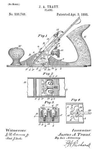
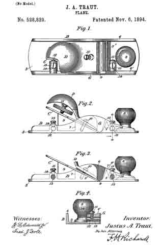
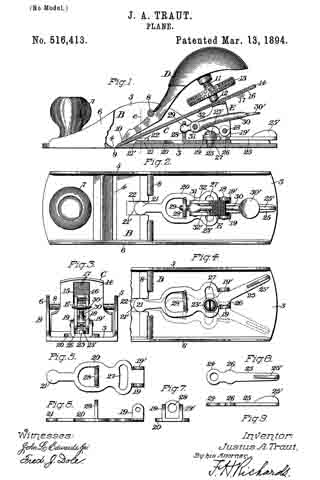
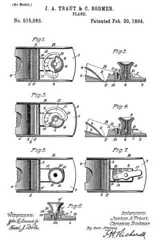
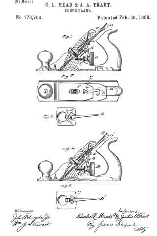
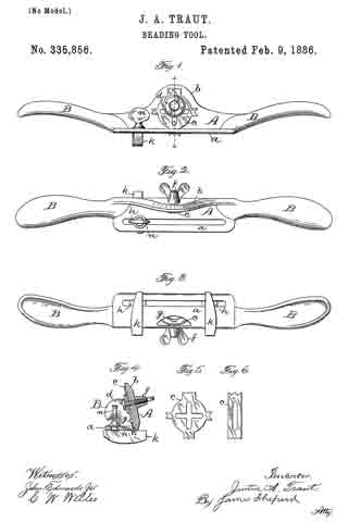
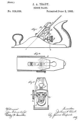
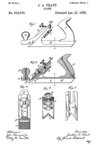
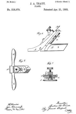
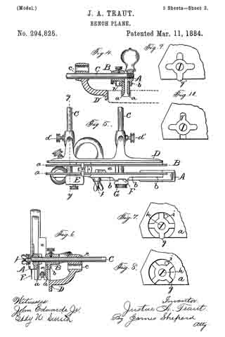
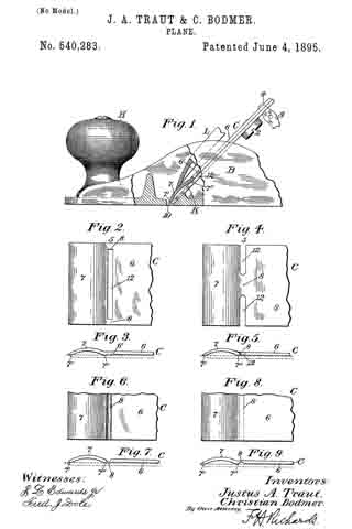
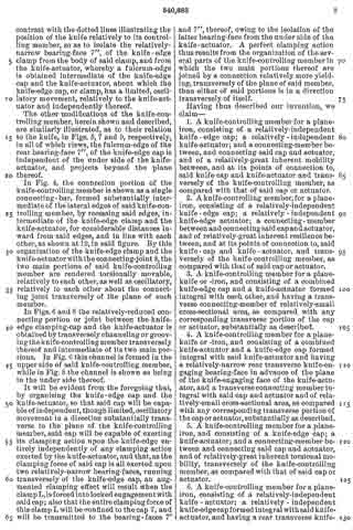
In the drawings accompanying and forming a part of this specification, Figure 1 is a side elevation, partially in section, of a portion of an ordinary smooth-plane furnished with our present improvement. Fig. 2 is a plan view of a portion of the knife-controlling member of the plane iron or knife embodying one form of our present improvement. Fig. 3 is an edge view of the cap shown in Fig. 2. Fig. 4: is a view similar to Fig. 2 and illustrating a modification of the cap shown therein. Fig. 5 is an edge view of the cap shown in Fig. 4. Figs. 6 and 8 are plan views similar to Figs. 2 and 4 for illustrating other modifications of the cap; and Figs. 7 and 9 are edge views of the forms of the cap shown in Figs. 6 and 8, respectively.
Similar characters designate like parts in all of the figures.
Our present improvement comprises a knife-controlling member for a plane-iron or knife, and having, in combination, a substantially-rigid knife-actuator, and a substantially-rigid knife-edge-cap or clamp formed integral with each other, and movable bodily, the one relatively to the other. It also comprises, in combination with said knife-actuator and the knife-edge cap, a resilient connection or spring-joint intermediate of said main portions of the knife-controlling member, and, in order to obtain a more perfect resilient relation between the knife-actuator and the knife-edge cap, the knife-engaging face of the cap, which is adjacent to said resilient connection, projects beyond the plane of the knife-engaging face of the knife-actuator, so that the knife-edge cap will have a full bearing upon the knife at both ends of said cap, and independent ofthe knife-actuator, and an oscillatory, yielding movement, transversely of the plane of the knife-controlling member, about the fulcrum or axis formed by the rear knife-engaging bearing-face or fulcrum-edge of the knife-edge cap.
We have shown, in Fig. 1, the principal portion of the body of the ordinary smooth-plane, of the class usually made of iron, and having the parts common to such planes, viz: a plane-iron or knife, a cap for the knife, a clamp for the cap, means in connection with the cap and adapted for adjusting the knife, a handle or knob at the front or left-hand end of the plane-body, and a handle (not shown), at the rearward or right-hand end of the plane-body.
In the drawings, the plane-body is designated in a general way by B, the plane-iron or knife by K, the knife-controlling member or cap by C, and the usual, forward handle, or knob, by H. This knife-controlling member or cap is shown affixed to the knife or plane-iron by means of the usual clamping screw 2; and a knife-actuating lever 3, which will be supported upon the frame or body of the plane in some usual or well known manner, is shown engaging in a mortise or slot, formed at the point 4 in the knife-controlling member, for the purpose of adjusting the knife and its controlling member together, upward or downward under the cap-engaging clamp L.
According to our present improvements, the knife-controlling member, which, as before stated, is designated in a general way by C, comprises two principal portions separated, at about the point 5, by a connection which will permit movement of one of the members, such as the knife-actuator 6, relatively to the other member, or knife-edge cap 7, in a direction transversely of the plane of said knife-controlling- member considered as a whole. This connecting member is shown herein, in the preferred form thereof, as a spring-joint, formed by a connecting portion or portions 8, of relatively-small cross-sectional area, transversely of the knife-controlling member, as compared with such area of said member at other points in the length thereof. This connection, which, in the forms of the device herein shown, constitutes a yielding or spring-joint, connects the knife-actuating portion 6 of said knife-controlling member with the knife-edge cap 7 thereof, in such a manner that these main portions are each movable, as a whole, relatively to the other, in a direction substantially transverse to the plane of said knife-controlling member, that is to say, each of said main portions has a slight, oscillatory movement, relatively to the other, about an axis intermediate of said main parts. In the manufacture of articles of this class, it has been found, that a perfect organization of the parts of a plane, — such as will bring the edge of the cap into exact parallelism with the cutting-edge of the bit- — is exceedingly difficult, owing to the liability of each member of the organization having a very slight error, when formed by the ordinary methods of manipulation. The clamping-edge of the cap, for instance, even if ground with precision, after tempering, and especially, if unevenly tempered, might not be an exact straight line in the direction of the plane of the bit, but have a slight bend in the same; and this is the frequent case in actual practice. Hence, it will be evident, that if provision is made for a slight torsional, or twisting movement of the cap, relatively to the actuator, a perfect and even bearing of the forward edge of the cap, upon the knife, will be assured.
It will be remembered that, in planes of this class, as ordinarily constructed, the cap generally employed, and which, in some of its features, is substantially similar to the knife-controlling member described herein, is required to be accurately adjusted relatively to the extreme or cutting edge 10, of the knife of the plane, so as to properly turn the shaving in the throat of the plane, as said shaving is stripped, by the knife-edge, from the body of the piece being planed. This adjustment is effected, in practice, by means of the set clamp-screw 2, the point of which is engaged in the knife-controlling member, and the shank of which travels in the usual, central, longitudinal slot in the plane-iron or knife.
When this clamp-screw is loosened, the cap may be adjusted longitudinally on the knife, with its forward end more nearly adjacent to, or more remote from, the cutting edge of the knife, and is then re-affixed to the knife by tightening said clamp-screw. The cap being properly adjusted, relatively to the knife, and the knife being also properly adjusted, with its cutting edge in the desired position relatively to the sole of the plane, this latter adjustment being effected by means of the lever 3, or other adjusting device, commonly employed for this purpose, the clamp L is then brought into locking engagement with the outer face of the cap-portion 7, of the knife-controlling member, and secured in that position, so as to hold the said clamp rigidly upon such knife-edge cap of the knife-controlling member, and thereby obtain a similar, rigid engagement between the bearing-faces 7′ and 7”, at the forward and rearward ends of the knife-edge cap, and the upper face of the plane-iron or knife, as shown in Fig. 1. The clamping force, exerted by the clamp L upon the arched knife-edge cap 7, readily springs or bends the relatively-small connecting portion, or spring joint 8, of the knife-controlling member C, thereby bringing both the forward edge 7′, of the clamp-portion or knife-edge cap of said knife-controlling member, and the rearward fulcrum edge 7”, thereof, into full bearing engagement with the plane-knife or plane-iron, so as to hold said knife and the knife-edge cap in full and proper bearing contact, the one upon the other, at all points in the transverse bearing-faces of the same, and this, notwithstanding any irregularity in the form of the actuator portion 6, of the knife-controlling member, or in the manner of fastening this actuator portion to the knife itself.
In all of the forms of our improvement, that are herein shown and described, the same general organization of parts is maintained, viz.: a knife-actuator and a knife-edge cap connected transverse to the plane of the knife-controlling member in which they are embodied, and a preferably resilient joint, intermediate of these main portions of the knife-controlling member, and forming said connection therebetween. In each case, the connecting-member, between the shaft and the actuator, is of relatively-great inherent mobility, or resilience, transversely of the knife-controlling member, as compared with the mobility, or resilience, of such cap or actuator; so that each transverse portion of the two main parts of the knife-controlling member will be of relatively-great inherent rigidity, as compared with the member which connects them.
In Fig. 2, the connection portion of the combined knife-actuator and knife-edge-clamp is shown consisting of the two edge-bars 8–8, tying together the two main portions, and at the ends of the elongated, transverse slot or opening 12. In this case these connecting bars constitute a relatively yielding portion, or spring-joint, entirely independent of the main portions of the knife-actuating member, except at the extreme lateral edges thereof; and, for the purpose of allowing this joint to operate more freely, the knife-actuator 6 will usually be slightly elevated at 6’, rearward of said joint, as shown in Fig. 3, by contrast with the dotted lines illustrating the position of the knife relatively to its controlling member, so as to isolate the relatively-narrow bearing-face 7”, of the knife-edge clamp from the body of said clamp, and from the knife-actuator, whereby a fulcrum-edge is obtained intermediate of the knife-edge cap and the knife-actuator, about which the knife-edge cap, or clamp, has a limited, oscillatory movement, relatively to the knife-actuator and independently thereof.
The other modifications of the knife-controlling member, herein shown and described, are similarly illustrated, as to their relation to the knife, in Figs. 5, 7 and 9, respectively, in all of which views, the fulcrum-edge of the rear bearing-face 7”, of the knife-edge cap is independent of the under side of the knife-actuator, and projects beyond the plane thereof.
In Fig. 4, the connection portion of the knife-controlling member is shown as a single connecting-bar, formed substantially intermediate of the lateral edges of said knife-controlling member, by recessing said edges, intermediate of the knife-edge clamp and the knife-actuator, for considerable distances inward from said edges, and in line with each other, as shown at 12, in said figure. By this organization of the knife-edge clamp and the knife-actuator with the connecting-joint 8, the two main portions of said knife-controlling member are rendered torsionally movable, relatively to each other, as well as oscillatory, relatively to each other about the connecting joint transversely of the plane of such member.
In Figs. 6 and 8 the relatively-reduced connecting portion or joint between the knife-edge clamping-cap and the knife-actuator is obtained by transversely channeling or grooving the knife-controlling member transversely thereof and intermediate of its two main portions. In Fig. 6 this channel is formed in the upper side of said knife-controlling member, while in Fig. 8 the channel is shown as being in the under side thereof.
It will be evident from the foregoing that, by organizing the knife-edge cap and the knife-actuator, so that said cap will be capable of independent, though limited, oscillatory movement in a direction substantially transverse to the plane of the knife-controlling member, said cap will be capable of exerting its clamping action upon the knife-edge entirely independently of any clamping action exerted by the knife-actuator, and that, as the clamping force of said cap is all exerted upon two relatively-narrow bearing-faces, running transversely of the knife-edge cap, an augmented clamping effect will result when the clamp L, is forced into locked engagement with said cap; also that the entire clamping force of this clamp L will be confined to the cap 7, and will be transmitted to the bearing-faces 7′ and 7” , thereof, owing to the isolation of the latter bearing-face from the under side of the knife-actuator. A perfect clamping action thus results from the organization of the several parts of the knife-controlling member in which the two main portions thereof are joined by a connection relatively more yielding, transversely of the plane of said member, than either of said portions is in a direction transversely of itself.
Having thus described our invention, we claim —
1. A knife-controlling member for a plane-iron, consisting of a relatively-independent knife – edge cap; a relatively-independent knife-actuator; and a connecting-member between, and connecting said cap and actuator, and of a relatively-great inherent mobility between, and at its points of connection to, said knife-cap and knife-actuator and transversely of the knife-controlling member, as compared with that of said cap or actuator.
2. A knife-controlling member, for a plane-iron, consisting of a relatively-independent knife-edge cap; a relatively-independent knife-edge actuator; a connecting- member between and connecting said cap and actuator, and of relatively-great inherent resilience between, and at its points of connection to, said knife-cap and knife-actuator, and transversely of the knife-controlling member, as compared with that of said cap or actuator.
3. A knife-controlling member for a plane-knife or iron, and consisting of a combined knife-edge cap and a knife-actuator formed integral with each other, and having a transverse connecting-member of relatively-small cross-sectional area, as compared with any corresponding transverse portion of the cap or actuator, substantially as described.
4. A knife-controlling member for a plane-knife or iron, and consisting of a combined knife-actuator and a knife-edge cap formed integral with said knife-actuator and having a relatively-narrow rear transverse knife-engaging bearing-face in advance of the plane of the knife-engaging face of the knife-actuator, and a transverse connecting member integral with said cap and actuator and of relatively-small cross-sectional area, as compared with any corresponding transverse portion of the cap or actuator, substantially as described.
5. A knife-controlling member for a plane-iron, and consisting of a knife-edge cap; a knife-actuator; and a connecting-member between and connecting said cap and actuator, and of relatively-great inherent torsional mobility, transversely of the knife-controlling member, as compared with that of said cap or actuator.
6. A knife-controlling member for a plane-iron, consisting of a relatively-independent knife-actuator; a relatively-independent knife-edge cap formed integral with said knife-actuator, and having a rear transverse knife-engaging bearing-face in advance of the plane of the knife-engaging face of the knife-actuator; and a connecting-member between, and connecting said cap and actuator, and of relatively-great inherent mobility, between, and at its points of connection to, said knife-cap and knife-actuator, and transversely of the knife-controlling member, as compared with that of said cap or actuator, substantially as described.
JUSTUS A. TRAUT.
CHRISTIAN BODMER.
Witnesses:
FRANCIS H. RICHARDS,
FRED. J. DOLE.