
No. 363,213 – Hand Or Jack Plane (Lester A. Dearth) (1887)
UNITED STATES PATENT OFFICE.
_________________
LESTER A. DEARTH, OF LACONIA, NEW HAMPSHIRE.
HAND OR JACK PLANE.
_________________
SPECIFICATION forming part of Letters Patent No. 363,213, dated May 17, 1887.
Application filed March 25, 1887. Serial No. 232,399. (No model.)
_________________
To all whom it may concern:
Be it known that I, LESTER A. DEARTH, of Laconia, in the county of Belknap and State of New Hampshire, have invented certain new and useful Improvements in Hand or Jack Planes, of which the following is a specification.
My invention relates to jack or hand planes, and has for its object to provide improvements in devices of that kind whereby the sole of the plane may be oiled (as is necessary in some classes of work) during the operation of smoothing or planing lumber therewith, and without the necessity of stopping work and employing a device separate from the plane itself for that purpose.
As is well known to carpenters, joiners, and others skilled in arts requiring the use of planes, it is essential in many kinds of work to oil the sole of the plane, and in instances where this thing is necessarily frequent much time is consumed thereby, as well as annoyance occasioned to the workman.
In carrying out my invention I utilize the knob secured to the upper face of the stock just in front of the slot provided for the escape of shavings as an oil-reservoir, in addition to its present uses, and combine means with said knob whereby the workman can from time to time, and while using the plane in the ordinary manner, supply oil to the sole thereof as may be needed.
I will now proceed to describe my invention, so that others may be able to make and use the same, reference being had to the accompanying drawings, and to the letters of reference marked thereon, forming a part of this specification, the same letters indicating the same parts wherever they occur, and the invention being particularly pointed out in the claims hereunto appended.
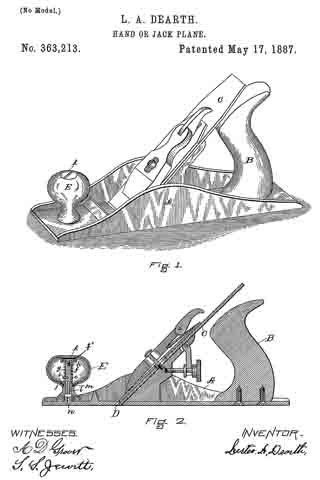
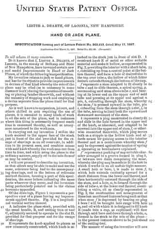
Of the drawings, Figure 1 represents a perspective view of a plane having my improvements applied thereto. Fig. 2 is a longitudinal vertical section thereof.
A indicates the plane-stock, provided with the usual handle, B, and cutting iron or tool C, adjustably secured to operate in the slot D, provided for that purpose and for the escape of shavings.
E represents the knob applied to planes as new commonly constructed, which knob is attached to the stock just in front of slot D. I construct knob E of metal or other suitable material and make it hollow, as represented in Fig. 2, providing the interior with a short tube, e, extending up from a central point at the bottom thereof, and form a hole of desired size in the top over tube e, the hollow of which latter feature extends through the bottom of the cup.
f represents a stem adapted to fit closely in tube e and to slide thereon, a spiral spring, g, surrounding said stem above tube e, and bearing at its lower end on the upper end of said tube and pressing at its upper end against a pin, h, extending through the stem, whereby the stem f is pressed upward in the tube, pin i, extending from the stern through a slot, j, in the tube, serving to limit both the upward and downward movement of the stem.
k represents a plug constructed to closely fit and slide in the hole formed in the upper end of the knob, as aforesaid, and adapted to be screwed into the upperend of stem f, or otherwise connected therewith, which plug serves both as a stopple to the hollow knob and affords means for gaining access to the interior thereof and as a contrivance whereby stem f may be depressed against the tension of spring g, operating as hereinabove explained.
f’ represents a packing of any suitable character arranged in a groove formed in plug k, or between two disks comprising the same, whereby the plug may be made to fit the hole in which it works in an oil and air tight manner. A small hole or bore, l, is made in stem f which hole extends vertically upward for a short distance from the lower end thereof, and then horizontally outward through the side of the stem, and a hole, m, is formed through the side of tube e, at the lower end thereof, constituting a valve, all as clearly represented in Fig. 2, the construction and arrangeinent of these last mentioned features being such as that when stem f is depressed by bearing on plug k bore l will be brought into range with hole m, and oil with which it is designed to fill knob E (made into a cup, as explained) will flow through said bore and down through a hole, n, formed in the stock to the sole of the plane — in the present instance shown to be just ahead of the cutting-tool.
The manner of using the invention will now be readily understood. The knob being filled with oil and the parts being arranged in position, as shown, the operator from time to time, as it may be necessary to oil the plane, as aforesaid, and without stopping his work, depresses stem f for a moment by pressing a thumb or finger thereon, releasing a drop or so of oil, which runs down through hole n, in the stock to the proper point on the sole of the plane.
By the means explained a material amount of time is saved to the workman, and by utilizing the knob common to nearly all classes or kinds of planes my invention is made cheap of construction and ready of application, as well as convenient in use.
Although I have been particular to describe the precise form and arrangement of the parts as here comprising my improvements, it is obvious that these may be varied within the limits of mechanical skill without departing from the nature or spirit of my invention.
Having thus described my invention, what I claim is —
1. In a plane, the combination, with the stock, of the knob thereon, made hollow or formed as an oil-cup, a valve in said knob or cup, and a spring-pressed stem or plug extending to the exterior of the knob, whereby the valve may be operated to release oil from the cup to oil the sole of the plane, as set forth.
2. In a plane, the combination. with the stock, of the knob thereon, made hollow or formed as an oil-cup and provided with the tube e, having hole m, and spring-pressed stem, f fitted to slide in said tube and provided with bore or hole l, substantially as set forth.
In testimony whereof I have signed my name to this specification, in the presence of two subscribing witnesses, this 19th day of March, 1887.
LESTER A. DEARTH.
Witnesses:
STEPHEN S. JEWETT,
S. E. BLACKSTONE.