No. 275,539 – Bench-Plane (Levi Culver Strong) (1883)
[paiddownloads id=”33″]275539


UNITED STATES PATENT OFFICE.

_________________

LEVI C. STRONG, OF ALBANY, NEW YORK, ASSIGNOR OF THREE-FOURTHS TO PETER KINNEAR AND CHARLES H. TURNER, BOTH OF SAME PLACE.

BENCH-PLANE.

_________________

SPECIFICATION forming part of Letters Patent No. 275,539, dated April 10, 1883.
Application filed July 15, 1882. (No model.)

_________________

To all whom it may concern:

Be it known that I, LEVI CULVER STRONG, a citizen of the United States, residing at Albany, in the county of Albany and State of New York, have invented new and useful Improvements in Combination Bench-Planes, of which the following is a specification.

I have produced an improved combination-plane for carpenters’ use, in which the stock is adapted for attachments for doing a variety of work, such as tonguing and grooving, beading, rabbeting, and various shapes of moldings, which meet all the requirements of the work in being interchangeable with the stock, giving all the conveniences of the separate and expensive styles of planes generally used for different styles of work.

In my improved plane the blade of the stock, which has heretofore been made integral therewith, constitutes the attachable and detachable form or mold corresponding with the form of the cutter used for the desired work, and which have heretofore been used as separate attachments to the stock-blade. A simple and effective fastening is provided for these interchangeable form-blades, whereby they are easily and quickly attached and detached from the stock, and rendered firm in such attachment. Each form-blade has a stem at or near the middle of its length, extending up from its top, and the stock has a socket adapted to receive the stem of each form-blade, and a thumb-screw for binding the stem within said socket, while grooves, recesses, or sockets serve to receive the upper corners of the form-blades to hold and brace them in line with the stock. The stem also serves to brace the form-blades laterally, so that the grooves, recesses, or sockets in the bottom of the stock need only be deep enough to lock the form-blades in line with the stock.

The particular matters which distinguish my plane from others will be made the subject of specific claims, and are illustrated in the accompanying drawings, in which —

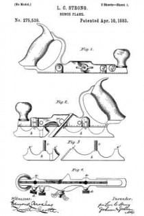
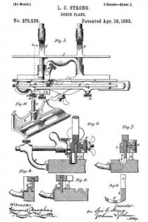
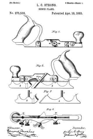
Figure 1 represents a side elevation of the stock of my improved combination-plane, showing the screws for clamping the interchangeable form-blades in the sockets thereof. Fig. 2 represents a similar view, showing the plow-blade clamped to the stock; Fig. 3, the two sections of the plow-blade or runner detached from the stock; Fig. 4, a bottom view of the stock, showing the sockets for the blade-stems; Fig. 5, a bottom view of the plane, with attachments for use as a plow, a dado, and a fillister or rabbet plane; Fig. 6, a cross-section of the same, taken on the line x x of Fig. 5; Fig. 7, a similar cross-section, showing the plane with a blade-form adapted for fluting or coving; Fig. 8, a similar section, showing the plane with a blade-form adapted for tonguing and grooving or matching. Fig. 9 shows a section of a blade-form for beading; Fig. 10, a perspective of the skeleton blade-form; and Fig. 11 shows blade-forms for hollows.

The stock is of metal, and has the usual handle, front knob, and middle inclined bearing or back for the bit, upon which it is secured by a bolt having an inclined side or wedge face passing horizontally through the stock, and adapted to clamp the knife-blade upon its inclined seat, in the manner shown and well known in bench-planes.

Hitherto metallic stocks of convertible bench-planes have been provided with attachable and detachable forms or molds of various shapes applied thereto as face-plates or runner-soles, in connection with cutters of corresponding form for performing a variety of work; but by my improvement the forms constitute also the blade of the stock.

The stock is formed with a vertical socket, a, about midway between the knife-bearing and each end, and the form and the runner blades b have each a stem, c, on their upper edges, at or about the middle of its length, adapted to fit into said socket. The form-blades are of two sections, and the front end of the rear section forms a continuation of the inclined knife-bearing. It is secured to the stock by a clamp-screw, d, at its outer side, which is enlarged by boss projections, screw-tapped, to receive the clamping-screws. This gives a secure and convenient fastening for the form-blades, and braces them laterally to the stock. To prevent the blades from turning upon the stem as a pivot, the stock has grooves, recesses, or sockets e in its under side, into which the upper corners, e’ e’, of the form-blades are inserted, and thereby lock the blades in line with the stock. Both form-blades are fastened in the same manner-one in front, and the other behind the bit — and the stock may have a shallow groove to receive the upper corners; but a continuous groove in the stock is not necessary, as the form-blades may have two or more vertical stems entering corresponding sockets in the stock to keep them in line therewith, as the middle stems and the clamp-screws form the fastening for the interchangeable form-blades. Of Whatever form of blade used, it is secured by the same means directly to the stock, and its sole or runner part b’ must correspond with the form of the cutter, and projects on the working side of the plane.

For plowing, rabbeting, fillistering, and dadoing, form-blades are not used, but blades as mere runners, as shown in Figs. 2 and 3, fastened, however, in the same manner as the form-blades.

The stock is provided with the usual horizontal detachable arms, screwed into the stock on each side of the bit, for receiving the supplemental stock e and the fence f which are used according to the character of the work, and made adjustable upon the arms.

The form-blades and the runner-blades extend equal distances from the bottom of the stock, and the fence is constructed so as to be set beneath the form and the runner blades when used without the supplemental stock. For this purpose the fence is carried by curved arms g in such manner that its upper edge will be at a level to allow it to be set so that its guide-face may come in vertical plane of the outer side or face of the blade of the form parts or of the runner, or in any intermediate positions, as shown in Figs. 7, 8, and 9. This gives the advantage of producing fluting or a cove, as in Fig. 7, or an edge or a center bead, as in Fig. 9, by the proper adjustment of the fence and the gage h, which is secured to the stock by a vertical stem and clamp-screw in the usual manner. This adaptation of the fence for adjustment beneath the form-blades and the runner gives a greater variety of work with a less number of attachments, which would otherwise be required with a fence of the usual construction.

The form-blade has an open or skeleton base or running surface, b’, and the blade part, b, proper is scalloped between its fastening stem and ends, which is important in reducing their weight to a minimum and lessening the friction.

I claim —

1. The combination of the stock provided with the vertical sockets a a and the bottom groove or recesses, e e, with the form or the runner blade b, having a vertical central stem, c, and end locking bearings, e’ e’, and the clamping-screws d d, tapped into the side of the stock, substantially as described, for the purpose specified.

2. In a combination bench-plane, the form-blades thereof, having an open or skeleton form surface and a vertical blade-stem, and adapted for attachment to a stock provided with vertical sockets, substantially as described.

3. In a combination bench-plane, the form and runner blades thereof, having each a vertical stem on its upper edge at or near the middle of its length, in combination with a stock having vertical sockets for said stems, and means, substantially as described, for fastening said stems to the stock, substantially as described.

4. The bench-plane herein described, consisting of the metal stock having the vertical sockets a a, the side screw-tapped holes entering said sockets at right angles thereto, and a bottom groove or recess, e, the form or runner blades b b’, having each a vertical stem, c, and corners e’ e’, and the screws d d, all constructed fer use substantially as herein set forth.

In testimony whereof I have hereunto set my hand in the presence of two subscribing witnesses.

LEVI CULVER STRONG.

Witnesses:
A. E. H. JOHNSON,
J. W. HAMILTON JOHNSON.

No. 275,538 – Bench-Plane (Levi Culver Strong) (1883)

[paiddownloads id=”332″]275538


UNITED STATES PATENT OFFICE.

_________________

LEVI C. STRONG, OF ALBANY, NEW YORK, ASSIGNOR OF THREE-FOURTHS TO PETER KINNEAR AND CHARLES H. TURNER, BOTH OF SAME PLACE.

BENCH-PLANE.

_________________

SPECIFICATION forming part of Letters Patent No. 275,538, dated April 10, 1883.
Application filed July 15, 1882. (No model.)

_________________

To all whom it may concern:

Be it known that I, LEVI CULVER STRONG, a citizen of the United States, residing at Albany,in the county of Albany and State of New York, have invented new and useful Improvements in Bench-Planes, of which the following is a specification.

I have improved the style of metallic bench-plane in which the knife is carried by a pivoted device and adapted thereby for adjustment in the arc of a circle to govern the depth of the cut. The objects of my improvements are, to provide by a single adjustment of the knife-carriage for producing a coarse or a thin shaving and a corresponding wide or narrow throat — that is to say, by a single adjustment of the knife-carriage to change the depth of the cut from a coarse to a thin shaving, the throat will be in proportion closed for fine work; to effect a greater range of adjustment of the knife or bit than is necessary for the greatest depth of cut to adapt the plane for cross-grain work and for hard and soft wood; to provide for increasing the width of the throat for the free passage of the shavings for either fine or coarse work independent of the pitch of the knife — that is to say, when a wide throat is required, without regard to the pitch of the knife or bit, as in planing across the face of a board, then the required width of throat is obtained by a horizontal adjustment of the knife-carriage upon the stock; and to provide a certain and positive adjusting and fastening device for setting and maintaining the knife or bit in whatever position it may be adjusted in relation to its carriage, while at the same time such adjustment may be easily and quickly effected for the finest work These objects I attain by the construction and means of adjustment illustrated in the accompanying drawings, in which —

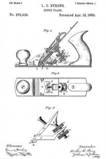
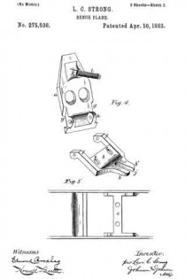
Figure 1 represents a vertical longitudinal section of a bench-plane embracing my invention; Fig. 2, a top view, the knife being removed to show the knife-carriage. Fig. 3 shows the two parts or sections of the knife-carriage and the adjusting device. Fig. 4 shows the two sections of the knife-carriage separated; and Fig. 5, a top view of so much of the stock as shows the seat upon which the knife-carriage is secured.

The stock of the plane is cast and provided with the usual throat for the knife and with the handle and front knob. The carriage for the knife or bit consists of two parts — viz., a seat-plate, a, upon which the knife is secured, and a base-plate, b, pivoted to the seat-plate, so that the latter can be adjusted in the arc of a circle upon its pivoted connection. The base-plate b is secured upon a raised rib, c, cast upon the upper side of the bottom of the stock by two screws, d d, passing through slots e e in the base-plate, whereby it may be adjusted horizontally in relation to the throat, its pivot joining with the seat-plate, as formed by arms f f the ends of which fit into recesses g g, preferably at the opposite edges of the seat-plate and against ears h h on its under side, through which and the ends of the arms the pivot-pin i passes, so as to bring the pivot-joined end of the seat-plate in close proximity to the rear edge of the throat. The rear end of the base-plate is curved or inclined upward and terminates in arms b’, so as to form a slot, j, in longitudinal central position with the stock. The seat-plate is formed with a boss or projection, k, on its under side, in the middle of its width and near its upper rear end, into which a screw-stem, l, is screwed tight, having a length sufficient to extend down through the slot j of the base-plate. Milled thumb-nuts m m are placed upon the screw-stem above and below the rear arms of the base-plate, and as the latter has a fixed relation to the stock the seat-plate can be turned upon its pivot-pin, so as to increase or diminish its angle or pitch by turning the thumb-nuts to the right or to the left, in which action one of said nuts will form a jam or lock nut against the arms of the base-plate, and thus form a positive and secure lock to the knife-carriage when set. The slotted end of the base-plate for this purpose stands high enough above the bottom of the stock to allow of easily manipulating the lower thumb-nut. This construction not only gives a very fine adjustment to the seat-plate, but affords the means by which it is secured against any accidental displacement from its adjustment. In making the adjustment the nuts are turned separately by the thumb of one hand, so that one nut follows the other up or down upon the screw-stem above and below the arms of the base-plate. The base-plate, the seat-plate, and the adjusting screw-stem and nuts constitute a device complete for attachment to the bottom of the stock, and for this purpose the seat-plate has holes through which to insert a. screw-driver to secure the base-plate to the stock.

The knife or bit n may be used either single or double, and is secured upon the seat-plate by a headed screw, r, tapped into said plate, its head passing through a slot in the knife-blade and through a locking-eye in the usual separate cap or clamp, which is provided with a fastening-screw or cam-lever, s, operating upon a spring riveted to the under side of the cap in the usual manner. In adjusting the bit or knife for a heavy or light cut by turning the thumb-nuts, the pitch or angle of the knife turning on its pivot-pin opens or closes the throat in proportion to the thickness of the cut, and one adjustment of the bit effects these two things. To give a freer passage for the shaving without moving the base-plate, set the knife for a coarse cut, and then, placing the plane on a flat surface, unclamp the cap, which allows the knife to slide up so as to bring its cutting-edge in position in the throat for a fine shaving.

If it is desired to work with the knife at at high pitch or angle and still have a narrow throat, the base-plate is set forward by removing the knife and unclamping the fastening-screws of the base-plate, and thus the plane is set for cross-grain work. The rib c of the stock is wide enough to give a good bearing for the base-plate and hold for its securing-screws, and high enough to carry the seat-plate free of the bottom of the stock.

I claim —

1. The combination of the stock of a bench-plane with a knife-carriage composed of two plates pivoted together at their front points, the upper one, a, of said plates having the rigidly-connected screw-stem l projecting from its rear or underside, and the bottom horizontal plate, f, adjustably connected to the bottom of the plane-stock, and having an upwardly-projecting slotted arm, b’, with means, substantially as described, for adjustably connecting the said screw-stem of the upper plate with the said slotted arm of the bottom plate, substantially as described.

2. The combination, in a bench-plane, of a carriage for the knife or bit, composed of the upper seat-plate, a, having the rigidly-connected screw-stem l, and a horizontal base-plate, f, adjustably secured to the bottom of the stock, and having an upward-projecting slotted arm, b’, the said plates being pivoted together at their front points, and the thumb jam-nuts m m, arranged upon said screw-stem and bearing upon the opposite sides of said slotted arrn, substantially as described, for the purpose specified.

3. The knife-carriage of a plane-stock, composed of the seat-plate a and the base-plate b, pivoted together, the former provided with a fixed screw-stem, l, and the latter having slots e e, and an elevated slotted part, b’ j, in combination with the adjusting lock-nuts m m, the base confining screws d d, and the knife or bit n, secured to said seat-plate, substantially as described, for the purpose specified.

4. In combination in a bench-plane, the stock, having the bottom rib, c, a knife-carriage of two pivot-joined parts, one, a, provided with a fixed screw-stem, l, and the other having an upward-projecting slotted part, b’ j, to receive said screw-stem, the thumb lock-nuts m m, the screws d d, and the knife or bit n, all constructed substantially as herein set forth.

5. The combination, with the stock and the knife or bit, of a carriage for the knife, composed of two pivot-joined parts, and means, substantially as described, whereby the upper of the pivot-joined parts is adapted for adjustment upon the lower part in the are of a circle, and the latter is adapted for adjustment horizontally with the upper part upon the stock, substantially as described, for the purpose specified.

6. The knife-carriage for a bench-plane, consisting of the base-plate b, having the front arms, f f the slots e e, and the rear upwardly-projecting slotted part, b’ j, the seat-plate a, having the front edge recesses, g g, and the ears h h, and the fixed screw-stem l, projecting downward from its rear end, the pivot-pin joining the arms f f and ears h h, and the adjusting thumb lock-nuts m m, arranged upon the screw-stem above and below said slotted base part j, all constituting a complete device for carrying, adjusting, and securing the knife to the stock, as set forth.

In testimony whereof I have hereunto set my hand in the presence of two subscribing witnesses.

LEVI CULVER STRONG.

Witnesses:
A. E. H. JOHNSON,
J. W. HAMILTON JOHNSON.