
No. 715,352 – Plane (Lewis M. Curry) (1902)


UNITED STATES PATENT OFFICE.
_________________
LEWIS M. CURRY, OF BRIGHTON , MICHIGAN.
PLANE.
_________________
SPECIFICATION forming part of Letters Patent No. 715,352, dated December 9, 1902.
Application filed March 29, 1902. Serial No. 100,512. (No model.)
_________________
To all whom it may concern:
Be it known that I, LEWIS M. CURRY, a citizen of the United States of America, residing at Brighton, in the county of Livingston and State of Michigan, have invented certain new and useful Improvements in Planes, of which the following is a specification, reference being had therein to the accompanying drawings.
My invention relates to improvements in carpenters’ planes; and its object is to provide a cheap and simple construction which is strong and durable, having few parts, easily assembled, and not liable to get out of order, and to provide ready means for accurately adjusting the plane-bit longitudinally within the throat and to so construct the parts as to allow for a slight lateral adjustment of the bit, it also being the object of this invention to provide means for clamping the bit and its shavings-breaker to the support therefor, so that they are firmly held without the necessity of a clamping-plate or other obstruction on the upper side of the breaker, and the bit will be frictionally held against accidental lateral movement thereby, but may be so adjusted by the operator.
To this end the invention consists in providing a longitudinally-movable carrier for the bit, which carrier is supported at an inclination substantially the same as that of the bed and free to move laterally on its support, and in providing suitable means for securing the bit to the carrier at one end, which means also serves to hold the lower end of the bit in strong frictional contact with the bed to prevent such lateral movement of the bit except when adjusted by the operator; and the invention further consists in providing suitable mechanism for moving the carrier and attached bit longitudinally to regulate the cut, and also in the particular construction, arrangement, and combination of parts, all as more fully hereinafter described, reference being had to the accompanying drawings, in which —
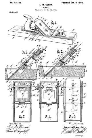
Figure l is a perspective view of a device embodying my invention; Fig. 2, a longitudinal vertical section through the bit and adjacent parts and a portion of the stock on the line 2 2 of Fig. 3. Fig. 3 is a section on the 2, showing a plan view of the line 3 3 of Fig. 2; Fig. 4, a section on the line 4 4 of Fig. 2, showing the carrier in plan; Fig. 5, the same, showing the carrier in section and illustrating the manner in which the bit is adjusted laterally; and Fig. 6 is a longitudinal vertical section similar to Fig. 2, showing a modified adjustment for the carrier and showing the bit unclamped to illustrate the manner in which it is held against the bed.
A is the stock of the plane, formed, in the usual manner, of hard wood, with a throat A’, having the mouth A2, and one side extended at an inclination of about forty-five degrees to form the bed A3, upon which the bit-iron or knife rests.
B is a casting secured to the top of the stock and provided with upwardly-extended supporting flanges or sides B’, which form bearings for the transverse pin C and eccentric-rod D, which support the bit-carrier E. Said carrier E consists of a rectangular casting having its middle portion cut away to lighten the same and provided with a lug E’, projecting from its lower end, which lug has an elongated opening E2 or slot through which the pin C extends, and through a transverse opening E3, near its upper end, extends the eccentric-rod D, which rod is provided with bearing ends D’ and D2 to engage the bearings in said sides B’. The rod D is set eccentrically to its bearing ends, so that when the same is turned by the knurled head D3, which is secured on the outer end of the reduced portion D4, the carrier will be moved a distance equal to the throw of said eccentric, and to secure the eccentric in place and connect the sides B’ a yoke F is provided, which embraces the sides B’ and is secured at its lower ends by the pin C, which extends therethrough and is riveted at its outer ends and near the top of the sides by the screws F’, said yoke extending over and closing the outer end of the opening forming the bearing for the end D’ of the eccentric and has an opening to at the reduced portion D4, thus securing the eccentric in place and forming a brace for the sides B’.
The knife or bit-iron G and its cap-iron or shavings-breaker H are secured together in the usual manner by a set-screw H’ engaging a slot G’ in the bit. The breaker is nearly as long as the bit and is provided with openings H2, having lateral extensions H3, located opposite the slot G’, to receive the heads of the screws I and J, which screws engage screw-threaded openings I’ and J’ in the carrier E, the head of the screw I forming an abutment to engage the upper side of the breaker.
The carrier E is supported at substantially the same inclination as the inclination of the bed A3, and the screw I is adjusted to bring its head at such a height relative to the bed that when said head is passed through the openings H2 and the breaker moved to engage the extension H3 with the shank of the screw the lower end of the bit will engage the bed adjacent to the mouth.
A binding-screw K engages a screw-threaded opening K’ in the carrier E, and on the inner end of said screw is a head K2, a recess K3 being provided in said carrier for said head, which head is forced upward by the turning of the screw into engagement with the under side of the bit and forces the lower end of the bit against the bed, the screw J being properly adjusted relative to the screw I to form a stop to prevent the bit from being bent too far by the action of the screw. The turning of the binding-screw K thus not only secures the bit to the carrier, but forces the same into frictional contact with the bed by the spring of the said bit, and by adjusting the screws I and J the frictional contact may be increased or diminished and the angle of the bit changed, so that it will lie flat upon the bed or will contact the same only at its lower end.
The carrier is made somewhat narrower than the space between the sides B’, and the eccentric is made to have a little play in its bearings, so that said carrier may be shifted laterally. When the bit is in place, the frictional contact thereof with the bed will hold the lower end of the bit so that when the upper end of the carrier is shifted the bit will be tilted to bring its cutting edge even with the sole of the stock when the bit is not ground exactly true, as shown in Fig. 5, and the spring action of the bit and its breaker causes a friction on the eccentric D, so that it will not be accidentally turned.
If desired, an adjusting-screw L, passing through an opening in the yoke F and engaging screw-threaded openings in the carrier, may be provided to move the carrier instead of the eccentric D; but I prefer said eccentric, as it is more accurate, is simple, cheap, and more durable.
Having thus fully described my invention, what I claim is —
1. In a plane, the combination with the stock; of side flanges on said stock, a bit, a movable carrier to which the bit is secured, and means supported by said flanges for supporting and moving the carrier to adjust the bit.
2. In a plane, the combination with the stock; of side flanges on said stock, a laterally-movable bit-carrier, a bit secured to said carrier, and means on the flanges for supporting the carrier and upon which it may be moved laterally of the stock to tilt the bit.
3. In a plane, the combination with the stock; of side flanges on said stock, a bit-carrier supported by said flanges and adapted to be moved laterally between the same, a bit on said carrier, and means for securing said bit to the carrier and for causing a frictional resistance to such lateral movement of the carrier.
4. In a plane, the combination with the stock; of a bit adapted to be moved longitudinally, side flanges on said stock and an eccentric supported by said flanges and adapted to move said bit.
5. In a plane, the combination with the stock thereof having a bed; of a carrier supported upon said stock and provided with screw-threaded openings a bit having an opening and engaging said bed at one end, a screw engaging one of the openings in the carrier and projecting through said opening in the bit to engage its head with the upper side of said bit, and a binding-screw engaging the other opening in the carrier and contacting the under side of said bit.
6. In a plane, the combination with the stock and a bit thereof; of supporting-flanges on said stock, a carrier to which the bit is secured, supported by said flanges to move longitudinally and provided with a transverse opening, and an eccentric within said opening.
7. In a plane, the combination with the stock thereof; of supporting-flanges on said stock, a carrier having a slot and a transverse opening, a pin supported by the flanges and engaging said slot, a rod in said opening having eccentric ends engaging bearings in said flanges, a bit, and means for securing said bit to said carrier.
8. In a plane, in combination a stock having a bed, supporting-flanges on said stock, a carrier having a slot at its lower end and a transverse opening near its upper end and screw-threaded openings, a pin secured at its ends to the supporting-flanges and extended through said slot, a rod in the transverse opening and having eccentric ends engaging bearings in the flanges, and provided with a head, a bit having openings, screws having heads projecting through said openings and engaging the upper side of the bit and adjustable in the screw-threaded openings in the carrier, a binding-screw extending through said carrier and a head on said binding-screw engaging said bit.
9. In a plane, the combination of a stock a casing secured to the upper side of said stock, the supporting-flanges on said casings having openings, a longitudinaily-movable carrier having a slot and a transverse opening, a pin extending through the opening in the flanges and the slot in the carrier, a rod engaging the transverse opening in the carrier and provided with eccentric ends engaging bearings in said flanges and having a reduced portion provided with a knurled head, a yoke embracing the flanges and provided with an opening to receive the reduced portion of the eccentric, and a bit secured to said carrier.
In testimony whereof I affix my signature in presence of two witnesses.
LEWIS M. CURRY.
Witnesses:
LEWIS E. FLANDERS,
OTTO F. BARTHEL.