No. 142,216 – Improvement In Planes For Cutting Cigar-Lighters (William H. Drips) (1873)

[paiddownloads id=”215″]142216


UNITED STATES PATENT OFFICE.

_________________

WILLIAM H. DRIPS, OF CINCINNATI, OHIO.

IMPROVEMENT IN PLANES FOR CUTTING CIGAR-LIGHTERS.

_________________

Specification forming part of Letters Patent No. 142,216, dated December 18, 1873; application filed June 24,1873.

_________________

To all whom it may concern:

Be it known that I, WILLIAM H. DRIPS, of Cincinnati, Hamilton county, State of Ohio, have invented a certain new and useful Plane for Cutting Cigar-Lighters, of which the following is a specification:

My invention consists of a small frame, to be placed temporarily upon a table or on the counter of a saloon, cigar-shop, hotel, or other similar place where cigars are sold, the frame containing a fixed plane blade and gage, by means of which the attendant can, with but little labor, make a sufficient number of curled shavings, adapted for cigar-lighters, to form a sufficient stock for the day.

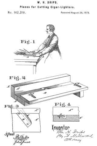
Figure 1 is a general view of my improved tool, showing the method of using my invention. Fig. 2 is a perspective vievv of the tool. Fig. 3 is a plan of the cutter-blade. Fig. 4 is a vertical section of a portion of the frame and cutter-blade.

A is a frame, formed of two strips, A’ A”, of wood, attached at right angles to each other, as shown. The horizontal strip, which rests upon the table or counter, has at one end a lip or flange, a, to engage the edge of the table and prevent it from slipping, said lip being preferably formed in one piece with the strip A’. A cutter-blade, B, of steel, is let obliquely into the plate A’, and secured permanently thereto at each end by screws. Below it is a circular recess, C, which receives the coiled shavings, and allows it to pass out upon the counter. The cutter B is not only let in obliquely in the direction of its length, but is also obliquely located in the direction of its width, so as to cause the shavings to curl anglevvise by its obliquity lengthwise, and cause the knife to present a cutting-edge by its obliquity crosswise. A gage or shield, D, is attached to strip A’ by screws d, the gage being slotted, as shown, to permit adjustment to suit different thicknesses of stud to be cut. This shield prevents the operator’s fingers from touching the knife in the act of pushing the stuff along, in the manner shown, to cut the lighters. The instrument may, however, be made and used without the adjustable gage.

I claim —

As a new article of manufacture, the tool for cutting cigar-lighters, substantially as described.

In testimony of which I hereunto set my hand.

WILLIAM H. DRIPS.

Witnesses:
FRANK MILLWARD,
J. L. WARTMANN.

No. 52,173 – Tools For Making Lighters (Albert Kleinschmidt And Francis Schlater) (1866)

[paiddownloads id=”112″]13957


UNITED STATES PATENT OFFICE.

_________________

ALBERT KLEINSCHMIDT AND FRANCIS SCHLATER, OF PHILADELPHIA, PENNSYLVANIA.

IMPROVEMENT IN TOOLS FOR MAKING LIGHTERS.

_________________

Specification forming part of Letters Patent No. 52,173, dated January 23, 1866.

_________________

To all whom it may concern:

Be it known that I, ALBERT KLEINSCHMIDT AND FRANCIS SCHLATER, of Philadelphia, Pennsylvania, have invented an Instrument for Making Lighters; and we do hereby declare the following to be a full, clear, and exact description of the same, reference being had to the accompanying drawings, and to the letters of reference marked thereon.

Our invention consists of a plane having a longitudinal groove, a diagonal cutter, and diagonal groove, the whole being arranged, substantially as described hereafter, so as to cut from a strip of wood coiled shavings of a tapering form, applicable to the lighting of cigars, &c.

In order to enable others to make and use our invention, we will now proceed to describe its construction and operation.

On reference to the accompanying drawing, which forms a part of this specification, Figure 1 is a side view of our plane for making lighters; Fig. 2, an inverted plan view, with parts of the plane removed; Fig. 3, a transverse vertical section on the diagonal line 1 2, Fig. 2, and Fig. 4 a transverse section on the line 3 4, Fig. 1.

Similar letters refer to similar parts throughout the several views.

A represents the body of the plane, which is similar, as regards external form, to ordinary planes, and is provided with the usual handle a. A cutter, B, passes through an opening in the body of the plane, and is secured by a wedge, C, the cutter being arranged diagonally and at the near edge of a diagonal groove, j, formed in the under side of the body of the plane. (See Fig. 2.)

It should be understood that the opening in the body of the plane for the reception of the cutter and wedge is entirely filled by the latter.

To the under face of the body of the plane are secured two strips, d and d’, so as to form a longitudinal groove, e, one of these strips covering part of the diagonal groove f, and thereby converting the latter into an opening, h, on one side of the plane, Fig. 1.

In operating with the above-described tool a piece of pine or other wood as free as possible frorn knots is selected, the piece being of the same width as or a trifle narrower than the width of the groove e between the strips d d’. The piece of wood is properly secured edge upward, and the operator, placing his plane so that the edge of wood is situated between the grooves, proceeds to remove shaving after shaving. Each shaving, as it is being cut from the wood, will, owing to the diagonal position of the knife and the groove f pass through the opening h in the form of a tapering coil, as seen at x, Fig. 3. The coiled shavings thus formed retain their uniform shape and neat appearance, and are especially useful for lighting cigars, &c.

We claim as our invention and desire to secure by Letters Patent —

The within-described plane, with its longitudinal groove e, diagonal cutter B, and diagonal groove j, the whole being arranged substantially as and for the purpose herein set forth.
In testimony whereof we have signed our names to this specification in the presence of two subscribing witnesses.

ALBERT KLEINSCHMIDT.
FRANCIS SCHLATER.

Witnesses:
CHARLES E. FOSTER,
JOHN WHITE.