
No. 240,076 – Spokeshave (Louis Bauer) (1881)

UNITED STATES PATENT OFFICE.
_________________
LOUIS BAUER, OF SAN FRANCISCO, CALIFORNIA.
SPOKESHAVE.
_________________
SPECIFICATION forming part of Letters Patent No. 240,076, dated April 12, 1881.
Application filed December 27, 1880. (No model.)
_________________
To all whom it may concern:
Be it known that I, LOUIS BAUER, of the city and county of San Francisco, State of California, have invented an Improved Spoke-shave; and I hereby declare the following to be a full, clear, and exact description thereof.
My invention relates to certain improvements in tools for working wood, leather, and other materials, these tools being known as “spokeshaves.”
My invention consists in a novel method of holding and clamping the blade of the shave in place between two clamping-jaws, so that any style of blade may be held in place and may be adjusted to or from the plate or edge, which serves as a gage.
My invention further consists in a means for setting the blade to or from the gage-plate, so as to regulate the cut, all of which will be more fully explained by reference to the accompanying drawings, in which —
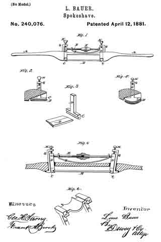
Figure 1 is a view of my tool. Fig. 2 is a transverse section. Fig. 3 is a detail view of the knife and holding-post. Fig. 4 is a longitudinal section. Figs. 5 and 6 are modifications of the cutter.
A is the handle or stock of my tool. This handle may be like the ordinary spokeshave, with two ends, or it may be carried back as a single handle, by which to draw or push the tool. It is fitted in the usual manner near the center, to admit the cutting-blade B.
In the ordinary construction of these tools the blade has two ends or tangs turned up and fitted to enter holes made transversely through the stock.
In my invention the blade B has its ends straight and made with wedge or other shaped edges, so as to be held firmly between suitable jaws, C. These jaws are formed upon the ends of posts D, which extend up through the stock A just at the ends of the cutter or blade.
These posts have their fulcrums in the stock, either by being pivoted in the slot, or they may simply be made a little smaller than the holes through which they pass, so that they may have a side movement or oscillation. Between the upper ends of these posts a bar, E, extends, this bar being formed in two parts with a screw-thread upon one or both, so that by means of a nut, F, in the center it may be lengthened or shortened. When the bar is made longer by turning the nut it forces the upper ends of the posts D apart, thus drawing the lower ends with their jaws together, and clamping the cutter-blade firmly between them. In the present case I have shown one part of the bar E made angular or pinned to one post, so as not to turn. This part has screw-threads upon it, while the other part has a nut to fit these threads, its opposite end turning loosely in its post. By this method of securing the cutter in place it may always be adjusted to or from the gage-plate and its proper distance maintained until it is entirely worn out.
It will be seen that any form of cutting-blade may be secured in this manner, the grooves in the bottom of the posts which receive the ends of the blade being straight or curved, as required.
The distance of the cutter from the stock may be regulated to make a thicker or thinner out by loosening the bar E and moving the posts up or down; but for delicate adjustment I employ a device constructed as follows:
G are posts which pass through the stock behind the posts D, and have their lower ends turned outward, or otherwise secured. Their upper ends are turned at right angles above the posts D, and screws H pass through them, so as to press upon the heads of the posts D. When these screws are turned in one direction they will force the posts D downward and move the blade or cutter away from the stock, thus leaving a wide slot. In order to return the blade and make the slot narrower the screws may be so connected with the posts D as to draw them back; but I have shown a flat curved spring, I, the ends of which are turned up and perforated, so that they slip over the ends of the bar E. The center of the spring presses upon the stock, and when the screws H are turned back the spring will force the posts D and bar E upward, thus drawing the knife or cutter closer to the stock. After the adjustment has been made satisfactorily, the bar E, which was previously loosened, may be again tightened, so as to hold the cutter in place.
The construction here described enables me to use a single stock for a number of cutters, and they maybe worn down to a narrow blade before being cast aside.
This tool is especially valuable for working leather, on account of its delicate and easy adjustment.
Having thus described my invention, what I claim as new, and desire to secure by Letters Patent, is —
1. The stock constructed with the inner curved faces, in combination with the blade or cutter B, having its ends beveled to fit corresponding grooves in the lower ends of the oscillating posts D, said posts having the straining rod or bar E extending between their upper ends, and provided with a nut, F, whereby the cutter may be clamped or released, substantially as herein described.
2. The oscillating posts D, with their straining-bar E fitted to hold the cutter B, as shown, in combination with the posts G, screws H, and spring I, whereby the cutter may be adjusted to or from the stock, substantially as herein described.
In witness whereof I have hereunto set my hand.
LOUIS BAUER.
Witnesses:
S. H. NOURSE,
FRANK A. BROOKS.