No. 371,482 – Bench-Plane (Eamor A. Teed And Frank B. Low) (1887)

UNITED STATES PATENT OFFICE.
_________________
EAMOR A. TEED, OF LOWELL, ASSIGNOR OF ONE-HALF TO JOEL A. BARTLETT,
OF CHELMSFORD, AND FRANK B. LOW, OF LOWELL, MASSACHUSETTS.
BENCH-PLANE.
_________________
SPECIFICATION forming part of Letters Patent No. 371,482, dated October 11, 1887.
Application filed March 12, 1887. Serial No. 230,651. (No model.)
_________________
To all whom it may concern:
Be it known that I, EAMOR A. TEED, a citizen of the United States, residing at Lowell, in the county of Middlesex and Commonwealth of Massachusetts, have invented a certain new and useful Improvement in Bench-Planes, of which the following is a specification.
My invention relates to bench-planes; and it consists in the means, hereinafter described, whereby the stock of the plane may in effect be lengthened to enable one plane to serve the purpose of one or more planes of greater length than the plane to which the improvement is applied.
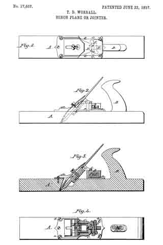
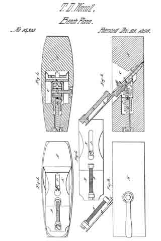
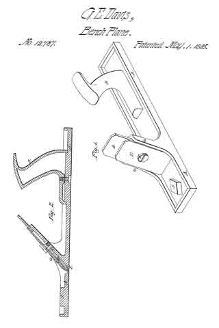
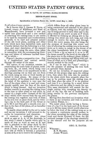
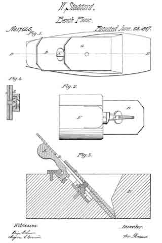
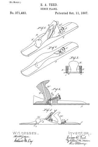
In the accompanying drawings, Figure 1 is an isometric perspective view of a plane with my improvement applied thereto; Fig. 2, an isometric perspective view of my improvement detached; Fig. 3, a vertical cross section on the line x x in Fig. 5; Fig. 4, a central longitudinal section of the rear part of the plane proper and the rear part of my improvement; Fig. 5, a central vertical section of my improvement and a side elevation of the plane.
The improvement, hereinafter described, may be applied to any so-called “iron bench-plane” — that is, a bench-plane having an iron stock — and is here shown as used in connection with a “Bailey smooth-plane,” the construction of which is well known and needs no particular description.
lt is sufficient to say that A represents the stock, a the plane-iron, and H H’ the plane-handles.
The only change that requires to be made in the plane proper to enable my improvement to be applied to it is to form two grooves, a’, one on each side of the stock leading from near the point of the same to said point, and providing the handle H’ with a depression, h, for purposes hereinafter stated.
My improvement consists of a shoe, S, which in general appearance is like the bottom and sides of the stock, but longer, and provided with an opening, s, through the bottom of the same, of a shape and size adapted to receive and fit the sole of the stock A. The shoe S is provided with pins s’, (shown in Figs. 2, 3,and 5,) adapted to enter the grooves a’ and to fit the same, and is also provided with a vertical post, s2, arranged in the rear of the slot s, which vertical post supports an inclined screw, s3, the head s4 of which is preferably milled to enable it to be turned readily by the fingers, the point of said screw entering the depression h, above mentioned as being formed in the handle H’, to prevent the rear end of the plane from rising out of the slot s. The relative positions of the grooves a’, pins s’, screw s3, and depression h, are such as to hold the sole of the stock A and the bottom of the shoe S in the same plane, the rear ends of the grooves a’ being at the same height above the sole of the stock as the pins s’ are above the bottom of the shoe, and the deepest part of the depression h fitting the point of the screw s3 and being at the same height above the sole of the stock as the point of said screw, when turned into said depression, is above the bottom of the shoe. The depression h, instead of being made directly in the wood of the handle, is preferably made in the head of a metallic screw, h’, driven into the handle against the screw h2, which secures the handle H’ to the detachable face-plate.
The plane is inserted in the shoe-point first and pushed forward until the pins s’ reach the rear ends of the grooves a’, and the rear of the plane is then depressed until the lower surfaces of the stock A and the shoe S are in the same plane. loosening the screw s3 the rear end of the plane may be lifted out of the slot s, and the stock being then drawn backward is disengaged from the shoe.
By means of the improvement above described a common smooth-plane can be used with the shoe as a fore-plane or jointer, and the expense of such a shoe is trifling compared with the cost of a plane, and the time required to apply or remove the shoe is of no importance.
I claim as my invention —
1. A shoe provided with a slot adapted to receive a plane-stock and means, substantially as described, of holding the bottom of said shoe in the same plane with the bottom of said stock, as and for the purpose specified.
2. The combination of the plane having a handle, and having a stock provided with grooves near its point, and a shoe slotted to receive said stock, and having inwardly-projecting pins adapted to enter and fits said grooves, and having a post, a screw turning in said-post and thrusting into a depression with which said handle is provided to hold the lower surfaces of said stock and shoe in the same plane, as and for the purpose specified.
EAMOR A. TEED.
Witnesses:
ALBERT M. MOORE,
EDWARD W. THOMPSON.
Corrections in Letters Patent No. 371,482.
It is hereby certified that the name of one of the assignees in Letters Patent No. 371,482, granted October 11, 1887, upon the application of Eamor A. Teed, of Lowell, Massachusetts, for an improvement in “Bench-Planes,” was erroneously written and printed “Frank B. Low,” whereas said name should have been written and printed Frank B. Dow. Also that errors appear in the printed specification requiring correction as follows: In line 75, page 1, the word “face-plate” should read shoe and in line 76, same page, the hyphen between the words “shoe” and “point” should be stricken out; and that the Letters Patent should be read with these corrections therein that the same may conform to the record of the case in the Patent Office.
Signed, countersigned, and sealed this 8th day of November, A. D. 1887.
[SEAL.]D. L. HAWKINS,
Acting Secretary of the Interior.
Countersigned:
R. B. VANCE,
Acting Commissioner of Patents.