No. 865,491 – Bench-Plane (Burton M. Graves And Frank N. Loson) (1907)

[paiddownloads id=”645″]865491


UNITED STATES PATENT OFFICE.

_________________

BURTON M. GRAVES AND FRANK N. LOSON, OF LOWVILLE, NEW YORK.

BENCH-PLANE.

_________________

865,491. Specification of Letters Patent. Patented Sept. 10, 1907.
Application filed May 7, 1906. Serial No. 315,549.

_________________

To all whom it may concern:

Be it known that we, BURTON M. GRAVES and FRANK N. LOSON, citizens ol the United States, residing at Lowville, in the county of Lewis and State of New York, have invented certain new and useful Improvements in Bench-Planes, of which the following is a specification, reference being had therein to the accompanying drawing.

Our invention relates to an improved bench plane, and we declare that the following is a lull, clear, concise and exact description thereof sufficient to enable one skilled in the art to make and use the same, reference being had to the accoinpanying drawings in which like letters and numerals refer to like parts throughout.

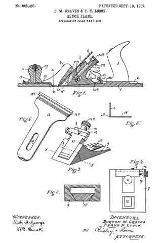
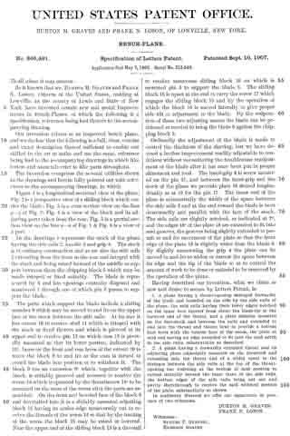
The invention comprises the several utilities shown in the drawings and herein fully pointed out with references to the accompanying drawings, in which Figure 1 is a longitudinal sectional view ot the plane; Fig. 2 is a perspective view of a sliding block which carries the blade; Fig, 3 is a cross section view on the line y–y Fig. 2; Fig. 4 is a view of the block and its adjusting parts taken from the rear; Fig. 5 is a partial section view on the line x–x of Fig. 1 & Fig. 6 is a view of a part.

ln the drawings 1 represents the stock of the plane having the side rails 2, handle 3 and grip 4. The stock is of ordinary construction and as are also the side rails 2 extending from the front to the rear and integral with the stock and being raised torward of the middle to support between them the chipping block 5 which may be made integral or fixed suitably. The blade is represented by 6 and has openings centrally disposed and numbered 7 through one of which pin 8 passes to support the blade.

The parts which support the blade include a sliding member 9 which may be moved to and fro on the upper face of the stock between the side rails. At its rear it has cutout 10 to receive stud 11 which is integral with the stock or fixed thereto and which is pierced at its upper end to receive pin 12 on which cam 13 is pivotally mounted so that its lower portion, indicated by 13a, bears on the front and rear faces of the cutout 10 to move the block 9 to and fro as the cam is turned to crowd the blade into position or to withdraw it. The block 9 has an extension 9a which, together with the block, is suitably grooved and recessed to receive the worm 14 which is operated by the thuinbscrew 14a to be mounted on the stem of the worm after the parts are assembled. On the front and beveled face of the block 9 and dovetailed into it is a slidably mounted adjusting block 15 having its under edge transversely cut to receive the threads of the worm 14 so that by the turning of the worm the block 15 may be raised or lowered. Near the upper end of the sliding block 15 is a dovetail to receive transverse sliding block 16 on which is mounted pin 8 to support the blade 6. The sliding block 16 is upset at the end to carry the screw 17 which engages the sliding block 15 and by the operation oi which the block 16 is moved laterally to give proper side tilt or adjustment to the blade. By the cooperation ol these two adjusting means the blade can be positioned as needed to bring the blade 6 against the chipping block 5.

Ordinarily the adjustment of the blade is made to control the thickness of the shaving, but we have devised a further improvement readily adjustable to conditions without necessitating the troublesome readjustment of the blade after it has once been put in proper alinement and feed. The hand-grip 4 is screw mounted on the pin 17, and between the hand-grip and the stock of the plane we provide plate 18 slotted longitudinally as at 19 lor the pin 17. The inner end of the plate is substantially the width of the space between the side rails 2 and at the end toward the blade is bent downwardly and parallel with the face of the stock. The side rails are slightly notched, as indicated at 2a, and the edges 18a of the plate 18 are extended to fit into said grooves, the grooves being slightly extended to permit to and fro movement of the plate so that the front edge of the plate 18 is slightly wider than the blade 6. By slightly unscrewing the grip 4 the plate can be moved to and fro to widen or narrow the space between its edge and the tip of the blade so as to control the amount of work to be done or material to be removed by the operation of the plane.

Having described our invention, what we claim as new and desire to secure by Letters Patent, is:

1. A plane having a throat-opening enlarged forwardly of the blade and bounded on the side by the side rails of the plane, the said rails having their lower edges notched on the inner face thereof from about the blade-tip to the forward end of the throat, and a plate slidably mounted on the fore-stock and between the rails and extended to and into the throat and thence bent to provide a bottom face level with the bottom face of the stock, the plate at said end having an edge extended to fit into the said notch in the side rails, substantially as described.

2. A plane having a forwardly extended throat and an adjusting plate adjustably mounted on the forestock and extending into the throat and of a width equal to the distance between the side rails at the top of the throat-opening but widening at the bottom of said opening to extend laterally beyond the inner faces of the side rails, the bottom edges of the side rails being cut out and partly therethrough to receive the said widened portion of the plate, substantially as shown.

In testimony whereof we affix our signatures in presence of two witnesses.

BURTON M. GRAVES.
FRANK N. LOSON.

Witnesses:
SAMUEL P. GURNSEY,
EMERSON GRAVES.

No. 779,246 – Bench-Plane (Alonzo St. John) (1905)

[paiddownloads id=”614″]779246


UNITED STATES PATENT OFFICE.

_________________

ALONZO ST. JOHN, OF LOWVILLE, NEW YORK, ASSIGNOR OF ONE-HALF TO F. N. LOSON, OF LOWVILLE, NEW YORK.

BENCH-PLANE.

_________________

SPECIFICATION forming part of Letters Patent No. 779,246, dated January 3, 1905.
Application filed February 6, 1904. Serial No. 192,420.

_________________

To all whom it may concern:

Be it known that I, ALONZO ST. JOHN, a citizen of the United States, residing at Lowville, in the county of Lewis and State of New York, have invented certain new and useful Improvements in Bench-Planes; and I do declare the following to be a full, clear, and exact description of the invention, such as will enable others skilled in the art to which it appertains to make and use the same, reference being had to the accompanying drawings, and to the letters of reference marked thereon, which form a part of this specification.

This invention relates to new and useful improvements in bench-planes, and the object of the invention is to produce a device of this character which will be simple in construction and having means for easily and rapidly adjusting the knife; and it consists, essentially, in the provision of a cam-shaped member, adapted to cause the knife-holding block to securely clamp the knife in an adjusted position while the operator still has hold of the handle of the stock of the plate, and in the provision of means for regulating the gage of the knife.

My invention consists, further, in various details of construction, combinations, and arrangements of parts, which will be hereinafter fully described, and then specifically deined in the appended claims.

I illustrate my invention in the accompanying drawings, which, with the letters of reference marked thereon, form a part of this application, and in which similar letters of reference indicate like parts in the views, in which —

Figure 1 is a vertical longitudinal section through my improved bench-plane. Fig. 2 is a detail perspective view of the knife-holding block. Fig. 3 is a sectional view on line 3 3 of Fig. 1.

Reference now being had to the details of the drawings by letter, A designates the stock of the plane, which is made of metal of any suitable kind and of any shape or size and has a knob A’ and a handle B of the usual construction. C designates a block of substantially wedge shape, the forward face C’ of which is recessed, the walls of said recess being inclined, forming a flaring recess widest at its bottom and adapted to receive a slide E, having its opposite longitudinal edges beveled and adapted to engage the inclined walls of said recess. On the rear of said slide E is an integral rack having teeth E’, which engage with a worm F, which is fixed to rotate with a shaft H, journaled in an aperture in said wedge-shaped member C. (Shown clearly in Fig. 1 of the drawings.) The outer end of the shaft H has a milled wheel H’, whereby the shaft may be carried in one direction or the other for the purpose of raising or lowering said slide. The upper end of said slide is recessed, as at e, and pivotally mounted upon a pin K. At the apex of said recess e is a bar N, at the outer end of which is formed a threaded eye N ’, adapted to receive the threaded shank portion of the shaft Q, which is journaled in the arms e’ of said slide. A lug n projects from the bar N at any suitable location and is adapted to engage an aperture in the knife R, whereby as the milled wheel T, fixed to the end of the shaft Q, is rotated in one direction or the other the bar N may be thrown slightly in one direction or the other for the purpose of adjusting the angle of the cutting edge of the planing-knife. It will be noted, however, that the pivotal movement of the bar N is very slight, such movement being afforded by having a loose connection between the threads upon the adjusting-screw T and the threads of the eye in said bar, and a very slight movement of the bar is sufhcient for any adjustment of the angle of the plane-iron.

Rising from the base of the stock is a bracket-arm O, carrying a pivot-pin O’, upon which a cam member J is mounted, said cam member being adapted to have a play in a recess a, formed in the upper surface of the horizontal projection of the member C and to bear against the inclined forward or rear edges of said recess for the purpose of causing the member C to be driven forward or withdrawn from clamping engagement with the knife, the forward throw of the handle end of said cam member being adapted to throw the block in clamping relation, so that the knife will be frictionally held against the cross-piece I, interposed between and integral with the stock of the plane, while the reverse movement of said cam will serve to withdraw the handle to allow the knife to be removed from the stock.

From the foregoing it will be observed that by the provision of a plane embodying the features of my invention the knife may be easily adjusted and locked in place upon the stock by the simple manipulation of the cam member, which may be actuated by one of the fingers of the operator while grasping the handle of the stock, and by turning the milled wheel T in one direction or the other the bar N may be thrown slightly to one side or the other for the purpose of regulating the angle of the cutting edge of the blade to the transverse slot through which it passes in the stock. When the plane becomes clogged with shavings, which especially happens when the wood is damp or wet, by giving a backward-and-forward movement to the cam the block may be withdrawn from the knife and the dust and shavings easily removed.

While I have shown a particular construction of apparatus illustrating my invention, it will be understood that I may make alterations, if desired, in the detailed construction of the same without in any way departing from the spirit of the invention.

Having thus described my invention, what I claim as new, and desire to secure by Letters Patent, is —

1. A bench-plane comprising a stock, a movable block mounted thereon and means for actuating the same, a shaft having a worm thereon swiveled in a recess in said block, a slide carried by said block and having rack-teeth on its rear face engaged by said worm, a bar pivoted to said slide, a lug projecting from the bar, a plane-iron engaged by said lug, and means for adjusting the angle of the plane-iron, as set forth.

2. A bench-plane comprising a stock, a movable block mounted thereon and means for actuating the same, a shaft having a worm thereon swiveled in a recess in said block, a slide carried by said block and having rack-teeth on its rear face engaged by said worm, a bar pivoted at its lower end in a recess in the outer face of said slide, a screw journaled in arms of the slide and passing through a threaded eye at the upper end of said bar, as set forth.

In testimony whereof I hereunto affix my signature in presence of two witnesses.

ALONZO ST. JOHN.

Witnesses:
FRED. B. MORSE,
WILLIAM J. D’ARAM.