No. 750,189 – Hand-Plane (Edward Haydock) (1904)

[paiddownloads id=”597″]750189


UNITED STATES PATENT OFFICE.

_________________

EDWARD HAYDOCK, OF MANCHESTER, ENGLAND.

HAND-PLANE.

_________________

SPECIFICATION forming part of Letters Patent No. 750,189, dated January 19, 1904.
Application filed December 14, 1901. Serial No. 85,900. (No model.)

_________________

To all whom it may concern:

Be it known that I, EDWARD HAYDOCK, a subject of the King of Great Britain, residing at 75 Ackroyd street, Higher Openshaw, Manchester, in the county of Lancaster, England, have invented a new and useful Improved Hand-Plane, of which the following is a specification.

This invention relates to hand-planes for woodworking, particularly pattern-making, in which curves and other irregular forms are required to be produced in patterns and core-boxes and other like work.

The object of my invention is to enable plane-irons with diiferent forms of cutting edges to be employed in a metallic stock having a flat sole in combination with a wood sole that is capable of being fixed to or removed therefrom, whose face is either formed to any preferred curve or of other required shape, and to provide means for holding said sole firmly in position; also, quick and automatic adjustment of the plane-iron.

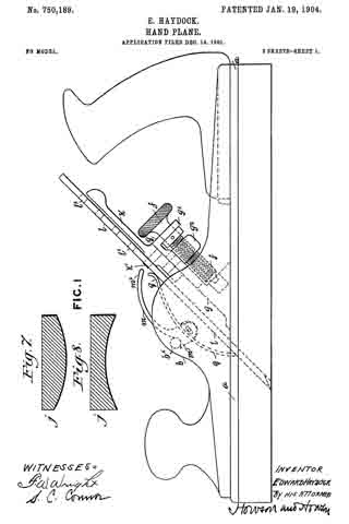
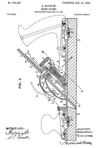
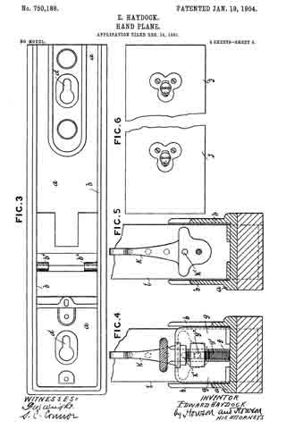
In the accompanying drawings, illustrating my invention, and to which I hereinafter refer, Figure 1 is a side view, and Fig. 2 a longitudinal section, of my improved plane. Fig. 3 is a plan of the stock-sole with the plane-iron and adjustments removed. Fig. 4 is an angular transverse section on line A B, and Fig. 5 a like section on line C D as seen in the direction of the arrow in Fig. 2. Fig. 6 is a plan of adjustable sole. Fig. 7 is a cross-section of a detachable convex wood sole for planing the inside of a cylinder, while Fig. 8 is a view of a concave sole for planing the outside of cylindrical bodies.

In the views the same letters refer to like parts.

According to this invention I form a metallic stock of malleable iron or steel, either cast or pressed, or other preferred metal, having key-shaped holes therein, as shown at d on plan in Fig. 3. These holes, are for the reception of small studs or set-screws c, which are fastened in small castings, as c’, fixed in an adjustable wood sole, as j. (Shown in Figs. 2 and 6.) The position of these castings in the adjustable sole corresponds with the holes in the stock-sole a. The facing on the upper side of the key-shaped holes d in the stock-sole is slightly taper to insure the screws c drawing the adjustable sole perfectly tight and rigid to the stock-sole when it is fitted thereon. The adjustable soles may be flat for ordinary smooth, jack, or trying plane purposes, or they may be of any required shape or radius for curves, core-boxes,or like work, as shown in Figs. 7 and 8. I fix a triangular slide g between the side walls b of the stock by means of screws inserted in the stock-sole.

The holes for the screws are slightly elongated to permit the slide to be moved a little backward or forward in order to alter the pitch of the plane-iron for planing different kinds of wood, either with or across the grain, as required. The aforesaid slide has a slot g’ formed lengthwise in its angular face, through which a square-headed stud g2 is passed. Said stud is square under the head and has a hole through the head, with a screw-thread formed therein. The projecting end of the stud is screwed or loosely riveted into a carrier or adjusting-lever k, which carries aplane-iron, as l, by means of a pin k’, that enters one of the small holes l’, formed at equal distances along the center of the plane-iron if a single iron is employed for radii or curved work or into a small hole in the back iron for ordinary planing. The aforesaid stud, with the plane-iron, is raised and lowered by a screw f, which is passed through the head of the stud g2, the neck of the screw being held in a lug gx at the top of the slide g and the bottom end resting in a footstep in said slide. The plane-irons are set square by the adjusting-lever k being turned a little to one side or the other and are held firmly in position by a curved spring q, the ends of which are pressed against the face of the plane-iron by a cam-lever m, the lower end of which is formed with a curved projection m’ at each side and hinged to the center of the aforesaid spring, as shown at qx in Fig. 2. A lug bx projects inwardly from each of the side walls of the plane, under which the curved projections m’ are placed when the lever m is in the position shown by dotted lines. When the free end mx of the lever is turned down, as shown, the spring q is compressed and the ends pressing on the face of the plane-iron keep it firmly in position, perfect and rapid means of adjustment being thereby obtained. The mouth of the plane if employed as an ordinary metallic plane without wood soles may be enlarged or reduced by a metallic slide p, fitted to the stock-sole by a stud passing through an elongated hole and secured by a nut. By these means a direct positive motion is obtained for forward feed and lateral adjustment of plane-iron, and if one iron is, ground to a two and one-half inch radius it would also work to any radius extending to about four inches without regrinding or altering. A quarter of a turn of the screw f would give one one-hundred-and-twelfth part of an inch, or thereabout, forward adjustment of the plane-iron, and by the lateral adjustment the inconvenience of exercising great care in sharpening or grinding the iron to correct form is avoided.

A sole-plate to do any kind of special work that is usually done by special planes may be made by the workman himself and fixed in the manner described for use as an ordinary smooth, jack, or trying plane.

I claim as my invention —

1. A hand-plane consisting of a metallic stock with keyhole-slots in the stock-sole, the enlarged opening of the keyhole being toward the front of the stock-sole, wooden soles carrying screws adapted to be passed through the keyhole-slots and inclined wedge-surfaces on one of the parts, whereby, upon forcing the metal stock forward the wooden sole will become secured to the metallic stock and by striking the rear of the sole it will become detached, substantially as described.

2. A hand-plane having a metallic stock with a flat sole-face, elongated recesses in said sole and a number of separate wood soles, each having a fiat surface and projections thereon adapted to fit into aforesaid recesses, the projections fitting the forward portion of said recesses loosely and fitting the rear portion tightly so that the sole may be slid against the surface of the stock to secure the wood sole to the metallic stock, whereby on striking the rear of the sole it will become detached, substantially as described.

In testimony whereof I have signed my name to this specification in the presence of two subscribing witnesses.

EDWARD HAYDOCK.

Witnesses:
THOS. PRESCOTT,
JNO. HUGHES.

No. 701,471 – Bench-Plane Guide (George G. Dennis) (1902)

[paiddownloads id=”563″]701471


UNITED STATES PATENT OFFICE.

_________________

GEORGE G. DENNIS, OF MANCHESTER, NEW HAMPSHIRE, ASSIGNOR OF
ONE-HALF TO GEORGE A. DOLBER, OF MANCHESTER, NEW HAMPSHIRE.

BENCH-PLANE GUIDE.

_________________

SPECIFICATION forming part of Letters Patent No. 701,471, dated June 3, 1902.
Application filed September 9, 1901. Serial No. 74,761. (No model.)

_________________

To all whom it may concern:

Be it known that I GEORGE G. DENNIS a citizen of the United States, residing at Manchester, in the county of Hillsboro and State of New Hampshire, have invented certain new and useful Improvements in Bench-Plane Guides; and I do declare the following to be a full, clear, and exact description of the invention, such as will enable others skilled in the art to which it appertains to make and use the same, reference being had to the accompanying drawings, and to the letters of reference marked thereon, which form a part of this specification.

This invention relates to improvements in bench-plane guides and contemplates a simple and durable guide adapted to be readily attached to iron planes and which in use is very efficient and is not liable to disorder.

The nature of my invention will be readily comprehended, reference being had to the following detailed description and to the accompanying drawings, in which —

Figure 1 is a perspective view of my improved guide attached to a plane. Fig. 2 is a longitudinal sectional view of the plane and an elevation of the attached guide. Fig. 3 is a cross-sectional view on line 3 3 of Fig. 2. Fig. 4 is a cross-sectional view on line 4 4 of Fig. 2.

Referring to the drawings by letter, A denotes an iron bench-plane, which may be of the usual construction. At one side of the plane is the usual vertical flange a, having an intermediate enlargement a’.

My improved guide is comprised of a frame B, having at its ends vertical extensions b b’ and an intermediate outwardly-projecting lug b2. At the rear side and toward the ends of the frame B are ears c c, apertured to receive pins d d, which pivotally connect to the frame the adjustable guide-plate E. The guide plate has at its outer side and centrally a slotted and apertured ear c’, to which is pivotally connected by a pin d’ one end of an arm f The other end of the arm occupies a slot b3 in the lug b2, and g is a thumb-nut, which is screwed into the lug against the arm to maintain the adjustment of the guide-plate.

The extension b is provided at its upper end with a return bend b4, which hooks over the flange a. To the upper end of the extension b is pivotally secured, by means of a pin d2, a cam H, having a handle h.

In attaching the guide to the plane the frame is slid toward the rear until the forward rise of the flange enlargement wedges tightly between the hook b and the forward ear c The cam is then turned to tightly clamp the body of the plane between it and the rearward ear c The guide is thus easily and quickly attached and detached and when in place is firmly held against movement.

I claim as my invention —

A guide for flanged bench-planes consisting of a frame having at one end an extension terminating in an integral hook to engage the flange, an extension at the other end of the frame, a cam pivoted on the latter extension adapted to clamp the body of the plane, ears on the frame, a guide-plate pivoted to the ears, a pivoted arm on the guide-plate adjustable in a slot in a lug on the frame, and a set-screw passed through the lug against the arm for maintaining the adjustment.

In testimony whereof I affix my signature in presence of two witnesses.

GEORGE G. DENNIS.

Witnesses:
GEO. W. PRESCOTT,
FRED T. DUNLAP.

No. 505,119 – Bench-Plane (Eppie J. McCulloch) (1893)

[paiddownloads id=”493″]505119


UNITED STATES PATENT OFFICE.

_________________

EPPIE J. McCULLOCH, OF MANCHESTER, NEW HAMPSHIRE.

BENCH-PLANE.

_________________

SPECIFICATION forming part of Letters Patent No. 505,119, dated September 19, 1893.
Application filed March 15, 1893. Serial No. 466,010. (No model.)

_________________

To all whom it may concern:

Be it known that I, EPPIE J. McCULLOCH, of Manchester, county of Hillsborough, State of New Hampshire, have invented an Improvement in Bench-Planes, of which the following description, in connection with the accompanying drawings, is a specification, like letters on the drawings representing like parts.

My invention relates to a bench plane and is intended as an improvement on a plane of the kind shown in Letters Patent No. 294,825, dated March 11, 1884, to which reference may be had, the object of the present invention being to enable the plane to be used for moldings and a variety of similar kinds of work which cannot be performed by the plane shown and described in the said patent. The plane shown in said patent, to which the present invention may be applied, comprises a body portion or stock made in two parts which are adjustable toward and from one another to vary the width of the stock of the plane, one of said parts which may be called the main stock or body of the plane being provided with suitable handles to operate the same, and also being provided with laterally projecting rods or pins upon which the other portion of the body, or auxiliary stock, is supported, being made adjustable upon said pins toward and from the main stock so as to vary and adjust the width of the body of the plane. The said pins also support an edge gage or fence which regulates the distance of the cut from the edge of the board or piece of material that is being planed. These parts are all shown in the before mentioned patent in which the main and auxiliary stocks are described as made of cast metal; and as shown in the said former patent they have blades rigidly and permanently secured to them by rivets or otherwise which blades run upon the surface of the wood being planed and govern the depth of each cut like the stock or body of an ordinary plane. The main stock is provided with a suitable clamp to hold the cutter or plane iron, and in the plane shown in the before mentioned patent the blade of the auxiliary stock necessarily has its lower edge or sole always on the same level as the lower edge or sole of the main portion of the stock.

The present invention consists mainly in making the sole portion of the auxiliary stock vertically as well as laterally adjustable with relation to the main stock thus adapting the plane for use with an iron or cutter having a curved or irregularly formed cutting edge, the auxiliary stock being adjusted laterally to support or co-operate with the said cutter by giving the requisite width to the body or stock of the plane, and the blade portion of the auxiliary stock being also adjustable in a plane parallel with the main stock and in line with the slope of the cutter or iron so that its lower edge may be brought to the proper height with relation to the adjacent portion of the cutter to properly co-operate therewith in governing the depth of the cut. In other words while the sole portion of the stock of an ordinary molding plane is commonly shaped to correspond with the shape of the edge of the iron, the plane forming the subject of the present invention has what may be regarded as a skeleton stock having but two lines of bearing upon the surface being planed, and the adjustments provided for by this invention enable the said bearing lines to be brought in proper position with relation to the cutter whatever the shape of its cutting edge may be.

Figure 1 is a side elevation of a plane embodying this invention; Fig. 2 a plan view thereof; Fig. 3 a side elevation of the body portion of the auxiliary stock detached; Fig. 4 a side elevation similar to Fig. 1, but with the gage removed; Fig. 5 a side elevation of the blade of the auxiliary stock detached, and Fig. 6 a transverse section on the broken line x6–x, Fig. 4.

The main portion aof the stock having the handles a2 and the blade or sole piece a3, the iron or cutter clamp a4 and the lateral rods a5, as well as the gage or fence b supported on said rods a5, may be of any suitable or usual construction, being herein shown as the same as in the bench plane shown in Letters Patent No. 294,825, before mentioned. The body portion c of the auxiliary stock may also be the same as in said patent except as to the means for connecting it with the blade or sole piece d, of said auxiliary stock, the said body portion being provided with sockets c2 to engage with the lateral rods a5 upon which the said auxiliary stock is adjustable laterally toward and from the main portion of the stock as in the patent before referred to, being secured in adjusted position thereon by suitable clamping screws c3. The said auxiliary stock has a suitable recess to accommodate the iron or cutter e and the portions at the front and rear of the cutter recess are connected by a lateral arch c4 which affords a free opening for the escape of shavings. Instead of having the blade or sole piece of the auxiliary stock made in two pieces each riveted or rigidly fastened to the body portion, one at the front and the other at the rear of the cutter recess, as in the before mentioned patent, so that nothing but lateral adjustability is provided for the sole portion of the auxiliary stock with relation to that of the main stock, the said blade or sole portion d is in accordance with the present invention preferably made in a single piece as best shown in Fig. 5, having a suitable recess d2 to accommodate the iron e and permit the escape of the shavings; or in other words the portions of said blade that are at the front and rear of the cutter or iron are connected by a portion d3 that extends over the top of the iron and the space in front of it. The said blade d is adjustably connected with the auxiliary portion c of the stock so that the lower edge of the said blade, forming the sole of the auxiliary stock, may be adjusted up and down with relation to the sole portion or blade of the main stock, as may be required to bring it to the proper relation to the cutter or iron when the edge of the latter is of such shape (as for example in the one shown in Fig. 6) that the portion of its edge which is nearest to the auxiliary stock must be at a different level from the edge of the blade a3 of the main stock in order to co-operate properly with the cutter. It is necessary for the proper co-operation of the blade d and the cutter e that the up and down adjustment of the blade d should be in line with the inclined cutter, and to properly provide for this the blade d is provided with slots d4 which embrace the lateral pins a5 of the main stock, while permitting the blade d to move up and down diagonally with relation thereto, and the body portion c of the auxiliary stock is provided with similarly inclined slots c5 to engage with fastening devices shown as clamping screws f extending into suitable holes d5 in the blade d. Thus by loosening the screws f the blade d may be slid up and down in line with the cutter e until its lower edge or sole portion is brought to the proper height to co-operate properly with the adjacent portion of the cutter so as to afford an additional or auxiliary support besides that afforded by the blade a3 of the main stock to regulate the depth of the cut and to guide the plane along the material being planed. The amount of up and down adjustment may be increased beyond the length of the slot c5 in the body of the auxiliary stock by having two or more suitably threaded screw holes d5 at different levels as shown in Fig. 5. By this construction the lower edge or sole portion of the blade of the auxiliary stock may be adjusted to any desired position both laterally and vertically with relation to the lower edge of the blade of the main stock, and the two thus constitute a universally adjustable stock which may be used with irons or cutters of any width and any shape of cutting edge within the limits commonly required for cutters having other than straight edges, thus greatly increasing the capacity of the tool over that of one in which there is no vertical adjustment of one portion of the stock relative to the other, so that it is in fact adjustable in width only.

I claim-

l. The combination of the main stock having a blade fixed thereon with an auxiliary stock laterally adjustable with relation to said main stock, and a blade supported on said auxiliary stock and vertically adjustable thereon, substantially as and for the purpose described.

2. The combination of the main stock having a blade fixed thereon and lateral rods or pins, with an auxiliary stock adjustably supported on said rods, a blade connected with the said auxiliary stock having slots parallel with the iron or cutter of the plane embracing the rods, and means for fastening the said blade at different heights on said auxiliary stock, substantially as described.

3. The combination of the main stock, its blade, and rods projecting laterally from said stock; with the auxiliary stock adjustably supported on said rods and provided with slots c5 parallel with the iron or cutter of the plane, the blade d provided with a recess for the cutter, and having slots d4 parallel with the cutter embracing the rods of the main stock, and clamping screws f extending through the slots of the auxiliary stock, substantially as and for the purpose described.

In testimony whereof I have signed my name to this specification in the presence of two subscribing witnesses.

EPPIE J. McCULLOCH.

Witnesses:
CHAS. E. COCHRAN,
P. J. O’DONNELL.