No. 716,386 – Plane (Maschil D. Converse) (1902)
[paiddownloads id=”576″]716386


UNITED STATES PATENT OFFICE.

_________________

MASCHIL D. CONVERSE, OF NEW YORK, N. Y., ASSIGNOR TO
JOHN J. TOWER, OF MONTCLAIR, NEW JERSEY.

PLANE.

_________________

SPECIFICATION forming part of Letters Patent No. 716,386, dated December 23, 1902.
Application filed October 29, 1901. Serial No. 80,470. (No model.)

_________________

To all whom it may concern:

Be it known that I, MASCHIL D. CONVERSE, a citizen of the United States, residing at New York, borough of Manhattan, in the county and State of New York, have invented new and useful Improvements in Planes, of which the following is a specification.

My invention relates to improvements in planes, and more particularly to means for securing and adjusting the irons thereof; and the objects of my invention are to improve the efficiency of such and to simplify the construction and reduce the cost of manufacture.

My invention is comprised in certain novel mechanisms, construction, arrangement, and combinations of parts hereinafter fully set forth and claimed.

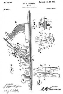
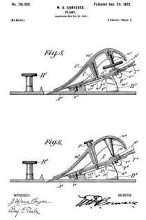
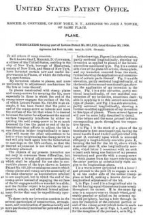
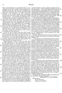
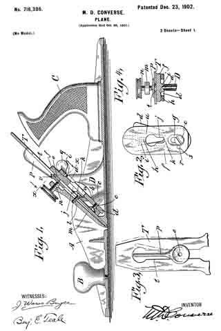
In the drawings, Figure 1 is a longitudinal vertical sectional elevation of a plane, of a type commonly known as “iron corrugated-bottom” planes, showing my invention incor-porated. Fig. 2 is a plan view of important parts of my invention, compassing the principal means for accomplishing vertical adjustment of the plane-iron. Fig. 3 is a plan view of the plane-iron and lateral-adjustment mechanism. Fig. 4 is a cross-section on line x x of Fig. 1; and Figs. 5 and 6 are views, partly sectional, illustratrating modilied constructions of my invention, all showing construction, application, and operation of my invention, as will be hereinafter more fully set forth in detail.

My invention may be applied to all types of planes, although I have shown it as applied to iron planes, as hereinbefore stated.

Planes have been made with mechanisms for vertical adjustment of the irons comprising bell-crank members and transverse grooves in the plane-irons to be engaged thereby pivoted to the body. Others have been made with mechanisms for vertical adjustment of the irons comprising bell-crank members and transverse slots in the plane-irons to be engaged thereby and pivoted to the body above the fulcrum-screw, and still others have been made with mechanisms for vertical adjustment of the irons comprising bell-crank members pivoted through the longitudinal slot of the plane-iron to a bed-piece at points above the fulcrum-screw and in engagement with notches in the cap-plate. Planes of such construction are expensive of manufacture, involving careful and accurate dimensioning of the throat and finishing of the ways and channels by difficult and tedious machining. In my present invention I overcome these disadvantages by novel arrangement and form of parts, dispensing entirely with the notches in the cap-plate and with the transverse grooves or slots in the plane-irons, rendering it wholly unnecessary to perform any expensive machining or fitting to compass a proper and accurate adjustment and holding of the plane-irons, all of which will be clearly seen and understood by those skilled in the art from the descriptions following.

Like letters indicate corresponding parts throughout the several figures.

A is the body of the plane, B a knob attached to the front portion thereof, and C the handle proper attached to the rearward portion.

D is a post and saddle-rest, which in case of iron-body planes is preferably cast integral centrally thereof. The apex of this post l prefer to make A-shaped, (distinctly shown at a, particularly in Fig. 4,) and the face thereof sloped to correspond with the incline b at its forward and broadened base c, the latter forming pivotal points and a rest for the extreme lower end of a vertical-adjustment lever d, which is pivoted thereto by a screw e. Upon the flattened upper surface of the pivoted end of the lever d rests the lower end of a flat saddle-plate f, which lower end is slotted longitudinally and recessed or countersunk on the upper side at g to receive the said pivot-screw e, which also serves to hold it in place, though admitting of a vertical sliding movement. Adjacent to the upper end of this saddle on the nether side a projection i is cast or formed, and a V-shaped groove h is formed therein to rest in slidable engagement with the sloping A-shaped apex a of the post D, which also serves to retain the same against lateral movement, a condition necessary for the carrying out of part of my invention. At a point centrally thereof and between the V-grooved projection i and above the slot g and pivot e is another opening in the saddle at j, the narrower lowermost end of which is recessed or countersunk on the under side at k to receive the head of the fulcrum screw or stud l when the same is slipped under the laterally-overhanging edges thereof. This fulcrum screw or stud l is secured in a clamping-plate m from its under side, (and I prefer to use a screw for convenience of adjustment.) In the upper end of the clamp-plate is a gnarled-head cramp-screw n, the rounded end of which engages a depression o of a lateral-adjustment lever p, serving as a pivot therefor. The vertical-adjustment lever d is provided at its upper end with a button q for operating. Midway of the ends and laterally of the slot g in the saddle f there is a hole r (see Fig. 2) for reception of a stud s, (freely fitting it, see same figure,) which stud is fixed (preferably rigidly) upon or in the vertical-adjustment lever d at a like position laterally relatively the axis thereof and pivot-screw e. This stud s and the hole r are located on a transverse line at right angles to the longitudinal vertical centers of the lever d and sliding saddle f, respectively, directly opposite the center of the pivot-screw e and sufficiently distant therefrom that it may not bind by describing an arc of too small a radius when the lever is operated.

For convenience and so that post D and projection i may not interfere therewith the lever d is open or divided at u and joined again above at the button q.

T is the plane iron or bit, which has a slot t longitudinally its center to admit of passage of the head and shank of the fulcrum-screw l therethrough.

In the modifications shown by Figs. 5 and 6 the principles of my invention hold, these modifications being such as render my invention applicable to what are known as “block-planes.” In the case of Fig. 5 the cramp-screw n5 is inverted and screw~socketed within and on the under side of the shell-like extension of the clamp-plate m5. The gnarled head of the screw being enlarged somewhat is accessible from the lateral sides, while in the case of Fig. 6 instead of a cramp-screw a projecting point n6 serves to engage the lateral-adjustment lever p6 as its pivot, and a gnarled head cramp-screw l6 is entered from the forward upper side through the clamp-plate m6 and engages a threaded hole k6 in the saddle f6.

The operation of my invention is as follows: To raise or lower the plane-iron T, push the button q to the left or right hand, which will cause the stud s to carry the saddle f up or down as the lever is rocked on its axis at e. To square the cutting end of the plane iron or bit with the throat of the plane, push the lever p to the right or left, as may be required, which causes the eccentric v to move the bit till the desired lateral adjustment is had. All these movements may be made without loosening the cramp-screw.

I do not limit myself to the specific form of the vertical-adjustment lever described herein, except that it should be located beneath the saddle f, which rests upon its lower end, and have its pivotal axis e and saddle-engaging stud s at its lowermost end or below the transverse plane of the fulcrum-screw and the apex of the post D, nor do I limit myself to the particular form of the post or of the saddle herein described, as manifestly they may be modified without departing from the spirit of my invention.

It will be readily understood by those skilled in the art that the novel construction and arrangement of the parts in my present invention, as well as their simplicity, make it possible to cast the same in metal to substantially finished form and dimensions, excepting the screws, thus saving the laborand cost of fitting.

I do not herein claim the lateral-adjustment mechanism shown, except in combination with the leading features of my present invention, for the reason that the same was allowed to me broadly by Letters Patent of the United States No. 619,394, dated February 14, 1899; but,

Having described my invention, what I do claim as new, and desire to secure by Letters Patent, is —

1. In a plane a vertical-adjustment mechanism comprising a laterally-movable lever pivoted centrally to the plane-body at a point below the transverse plane of the fulcrum-screw and of the apex of the post; a stud located thereon on the top side and laterally opposite its axis, a saddle engaged by said stud held in place by the pivot-screw of said lever, and slidably resting upon the pivoted end of the same and upon the apex of a post above said fulcrum-screw, in combination with a plane-iron and means for clamping the latter upon said saddle.

2. In a plane a laterally-movable lever pivoted centrally to the plane-body at a point below the transverse plane of the fulcrum-screw and of the apex of the post; a stud located thereon on the outer side and laterally opposite its axis; a saddle engaged by said stud held in place by the pivot-screw of said lever and slidably resting upon the pivoted end of the same and upon the apex of a post, above said fulcrum-screw; a plane-iron and means for clamping the same upon said saddle, in combination with mechanism for lateral adjustment of the plane-irons.

3. In a plane a vertical-adjustment mechanism comprising a laterally-movable lever pivoted centrally to the plane-body at a point below the transverse plane of the fulcrum-screw and of the apex of the post; a saddle slidably resting upon the pivoted end of said lever and upon the apex of a post; a laterally-located stud operatively connecting said saddle and said lever below the transverse plane of the fulcrum-screw, and a plane-iron, in combination with a lateral-adjustment lever eccentrically pivoted at the upper end of a clamp-plate.

4. In a plane a vertical-adjustment mechanism comprising a laterally-movable lever pivoted at its lower end; a saddle slidably resting upon the pivoted end of said lever and upon the apex of a post removed from the pivoted end of said lever, in combination with means for operatively connecting said lever and said saddle at their respective lower ends to accomplish vertical movement of the latter.

5. In a plane a laterally-movable pivoted vertical-adjustment lever, having an opening u centrally thereof, in combination with a saddle operatively engaged by said lever and having a groove h longitudinally central thereof on its under side contacting with the apex of a central post D within the plane-body and held in place by the pivotal screw of the lever.

6. In a plane a laterally-movable pivoted vertical-adjustment lever, having an opening fa centrally thereof, in combination with a post D projecting within said opening.

MASCHIL D. CONVERSE.

Witnesses:
WARREN W. WHITNEY,
J. MEACH.

No. 661,010 – Plane (Maschil D. Converse) (1900)

[paiddownloads id=”549″]661010


UNITED STATES PATENT OFFICE.

_________________

MASCHIL D. CONVERSE, OF NEW YORK, N. Y.,
ASSIGNOR TO JOHN J. TOWER, OF SAME PLACE.

PLANE.

_________________

SPECIFICATION forming part of Letters Patent No. 661,010, dated October 30, 1900.
Application filed March 19, 1900. Serial No. 9,276. (No model.)

_________________

To all whom it may concern:

Be it known that I, MASCHIL D. CONVERSE, a citizen of the United States, residing in the city of New York, borough of Manhattan, county of New York, and State of New York, have invented certain new and useful Improvements in Planes, of which the following is a specification.

My invention relates to planes, and more particularly to adjustment mechanisms for the bits or irons thereof.

In planes constructed with clamp-plates and cramp-screws for securing the bit, more especially in those in which the end of the cramp-screw engages the surface of the bit, of which Letters Patent No. 619,394 is an example, it has been found that the point or end of the cramp-screw so indents and mars the surface of the bit that when it is desired to loosen the latter for adjustment the marred surface frequently interferes by either requiring the said cramp-screw to be so much loosened (to free the point or end of the indentations) that efforts to adjust the bit in one direction (either longitudinally or laterally) will cause the other adjustment to be lost or when retightening the cramp-screw its end will slip back again into the indentation or marrings on the bit’s surface, so that the desired adjustment is not with facility and certainty attained.

The objects of my present invention are not only to overcome these difficulties, but to provide a lateral adjustment mechanism which shall be adapted for use also in convertible planes of the type shown in Letters Patent No. 620,226 or analogous ones in which clamp-plates and cramp-screws essentially of the same character as hereinbefore referred to are employed, but in which the end of the cramp-screw instead of engaging the surface of the bit engages a slide or a socket in a slide, and the further object is to provide an inexpensive, simple, and efficient lateral adjustment device that may be expeditiously operated.

To these ends my invention consists in the several particulars of construction, arrangement, and combination of parts severally and more particularly hereinafter pointed out and claimed.

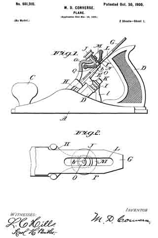
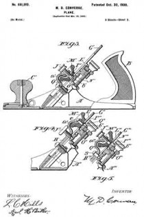
In the drawings, Figure 1 is a side elevation, partly sectional longitudinally, showing my invention as applied in planes of the herein-above first-mentioned type. Fig. 2 is a nether side view of the plane bit or iron, clamp-plate, and my invention removed from the stock, further showing the application and construction of certain parts thereof. Fig. 3 is a side elevation, partly sectional longitudinally, of the hereinabove second-mentioned type, showing the application of my invention to the same. Fig. 4 is a side elevation, partly sectional longitudinally, of one modiiied construction of my invention, sometimes desirable in applying it to this second-mentioned type of planes; and Fig. 5 is a side elevation, partly sectional longitudinally, showing a further-modified application of my invention to this type of planes. These several figures will now be more fully described in detail.

Like letters and the same primed indicate corresponding parts throughout the respective figures.

A in Fig. 1 is the stock of a plane of the hereinabove first-mentioned type, having the usual handle B and knob C and provided with a post D, centrally upon which is mounted obliquely a longitudinally-movable plate E, forming the bed for the bit G, above which is another plate H, also longitudinally movable, which latter I construct with an arch a (said arch being one feature of my present invention) and provide with a cramp-screw J, which passes from the upper side through the outer portion at substantially right angles to its longitudinal plane.

I is a worm-screw (provided with a lever l and pivoted to the post D) to engage a rack K on the under side of the nether clamp-plate or bed E, making a known device for longitudinal adjustment of the bit.

L in Figs. 1 and 2 is a longitudinal slot in the bit having equal dimensions transversely throughout its extent. M in the same figures is a concave-convex thumb-wheel, preferably gnarled or milled on its extreme upturned periphery, having a hole through its axis for reception of the reduced portion or end of the cramp-screw (which latter is made with a shoulder N, as in Figs. 1, 3, and 5) or for the reception of the journal e, as in Fig. 4. This thumb-wheel is provided with an eccentric O, (which I prefer to be integral,) extending from the convex side to enter the slot L and engage the lateral parallel walls thereof. The diameter of this eccentric should be so nearly equal the transverse measurement of the slot L as barely to slide freely therein. The surface immediately surrounding the eccentric radially on the convex side of the thumb-wheel at P, I level or flatten in order that the same may have a considerable area for engagement with the upper side of the plane-bit G by overhanging the lateral margins of the slot L. The arch ct of the clamp-plate H is for the accommodation of the upturned periphery of the thumb-wheel, which latter is so made in order that it may be accessible to the thumb and finger of the operator.

At Q it will be seen that the hole in the axis of the thumb-wheel on the convex side is countersunk and that a portion of the reduced pivot or pivot end is upset at b, so as to prevent the said thumb-wheel from becoming separated from the clamp-plate H when the bit is being removed.

Those skilled in the art will now see that in the operation of my invention the upturned periphery of the thumb-wheel gives convenient access (as before stated) for its manipulation by the thumb and finger of the operator, a construction for the thumb-wheel made possible when placed below the clamp-plate H by the arch a of the latter, that turning the thumb-wheel to either the right or left will accomplish lateral adjustment of the bit, and that the overhanging radially-extended flattened surface of the convex side of the thumb-wheel at P offers an area of sufficient extent to prevent indentation or marring of the surface of the bit, which it engages when the cramp-screw J is tightened, and because the point or end of the cramp-screw is not employed to engage the bit, but its pressure is communicated to the latter by means of the shoulder N, through the thumb-wheel, the under or convex side of which latter bears upon and binds the bit, except in the modification shown by Fig. 4, where the journal or pivot of the thumb-wheel and eccentric is independent of the cramp-screw and is not axially coincident therewith, which cramp-screw, however, in such case does not engage the surface of the bit, but engages a slide or a socket in a slide, as before mentioned, while in the modification shown by Fig. 5 a stud S is fixed in the clamp-plate to engage the socket in the slide (but without pressure on the bottom of the socket) instead of the cramp-screw. The advantages of the device of an arched clamp-plate H, with a thumb-wheel of the form described, will also be readily seen by such both on account of great economy of manufacture (since they severally may be cast in integral parts) and greater efficiency and convenience in operation.

I do not herein claim, broadly, the application of a lateral bit-adjustment mechanism to have its fulcrum coincident to the axis of the cramp-screw, such having been claimed and allowed to me in Letters Patent No. 619,394, dated February 14, 1899, nor do I wish to limit myself in my present invention to a combination with the cramp-screw as a pivotal axis therefor, since manifestly the improved form and construction of the leading features of my present invention adapt it to be employed on an independent pivot similarly to that shown in Fig. 4.

Having described my invention, what I do claim as new, and desire to secure by Letters Patent, is —

1. In a plane a lateral bit-adjustment mechanism comprising an arched clamp-plate carrying a pivot and cramp-screw, a concavo-convex thumb-wheel revolubly mounted on said pivot, provided with an eccentric on its convex side and a radially-flattened surface thereon adjacent to said eccentric, in combination with a longitudinally-slotted bit.

2. In a plane a lateral bit-adjustment mechanism comprising an arched clamp-plate carrying a shouldered pivot and cramp-screw, a concavo-convex thumb-wheel revolubly mounted on said pivot, provided with an eccentric on its convex side and a radially-flattened surface thereon adjacent to said eccentric, in combination with a longitudinally-slotted bit.

3. In a plane a lateral bit-adjustment mechanism comprising an arched clamp-plate carrying a pivot and cramp-screw, a concave-convex thumb-wheel revolubly mounted on said pivot, provided with an eccentric on its convex side and a radially-flattened surface thereon adjacent to said eccentric and means for preventing the said thumb-wheel from becoming accidentally detached from said clamp-plate, in combination with a longitudinally-slotted bit.

In testimony whereof I afiix my signature in presence of two witnesses.

MASCHIL D. CONVERSE.

Witnesses:
H. S. WELCH,
FRANK A. JONES.

No. 619,394 – Bench-Plane (Maschil D. Converse) (1899)

[paiddownloads id=”538″]619394


UNITED STATES PATENT OFFICE.

_________________

MASCHIL D. CONVERSE, OF NEW YORK, N. Y.,
ASSIGNOR TO JOHN J. TOWER, OF SAME PLACE.

BENCH-PLANE.

_________________

SPECIFICATION forming part of Letters Patent No. 619,394, dated February 14, 1899.
Application filed June 20, 1898. Serial No. 683,931. (No model.)

_________________

To all whom it may concern:

Be it known that I, MASCHIL D. CONVERSE, a citizen of the United States, residing in the city, county, and State of New York, have invented certain new and useful Improvements in Bench-Planes, of which the following is a specification.

My present invention relates more especially to that type of bench-planes commonly made with iron stocks, and particularly to sidewise-adjustment mechanisms for the same.

Planes have been provided with mechanisms for lateral adjustment that in many cases are so constructed, disposed, and applied as to involve piercing of the bits with holes or slots or cutting of grooves longitudinally in one or the other of the flat sides thereof, requiring in consequence that the bits be made thicker and heavier than is desirable to compensate for the lack of stiffness that would result from such form in the bit and otherwise, and in other cases the construction and manner of disposing and applying such mechanisms are such that they encroach upon the radial hand-space about the handle of the plane, more especially on the front side thereof, seriously interfering with and sometimes to the injury of the hand of the operator, and by such near proximity, especially of the free ends of the operating-levers, the bits are constantly liable to be and are thereby frequently accidentally disturbed and put out of lateral adjustment.

The objects of my invention are to overcome these defects, to simplify construction, reduce the cost of manufacture, and improve the efficiency of such tools.

My invention consists in placing the fulcrum-point of a mechanism for lateral adjustment of the plane-bit at the bearing end of a cramp-screw in the outer end of the upper bit-clamp plate or in axial coincidence therewith and in so constructing and disposing all parts of said mechanism that the objects above stated will be attained, all of which will hereinafter be fully described and claimed.

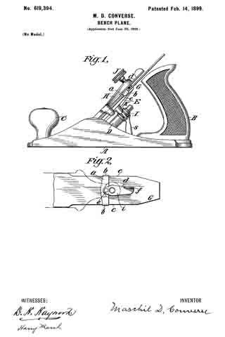
In the drawings, Figure 1 is a side elevation of a bench-plane of the class referred to, showing the construction, application, and disposition of the members in part of my invention. Fig. 2 is a plan view of parts of Fig. 1, showing further the construction, application, and operation of my invention. These figures will presently be more fully described in detail.

Like letters indicate corresponding parts in each figure.

A is a stock, block, or body of a bench-plane of common pattern, having the usual handle B, knob C, and a post D, centrally upon which is mounted a longitudinally-movable inclined plate E, forming a bed for the bit G, above which is another plate H, also longitudinally movable, with a cramp-screw J passing through its outer extremity from the top side, which, together with the said named plates E and H, comprises a screw-cramped clamp for securing the bit G after its adjustment laterally and longitudinally is effected.

I is a worm-screw (provided with a lever s) fastened pivotally to the post D to engage a rack K on the nether bit-clamp plate or bed E, making a known device for adjustment of the bit longitudinally.

a is a metal strap or casting, preferably arranged on the upper side, with ends b b turned right angularly to embrace the outer parallel edges c c of the bit G.

d is a lever operatively pivoted to the center of the strap at e, said lever being fulcrumed on the bearing end of the cramp-screw J in the outer end of the plate H and preferably arranged in a plane above the lateral plane of the bit G. The free end f of this lever d, which is also preferably disposed along the upper side of the bit, is suitably elongated and formed up to insure ease and accuracy of movement in manipulation.

The clamp-plates E and H are so attached to each other and to the post D, which is integral with the stock A, that while each has longitudinal freedom they have substantially no edgewise play. Therefore the fulcrum of the lever d, being on the bearing end of the cramp-screw J at the outer end of the upper bit-clamp plate H, is substantially fixed against lateral movement relatively the plane-stock A. The bit G, on the contrary, is fitted so as to have considerable edgewise freedom at its outer end, while the cutting end is confined against lateral movement, the purposes of which are apparent.

The mechanical operation will be readily understood without further explanation; but it should be specially noted that by a mechanism for lateral adjustment having the disposition of parts with the location and means of fulcrumage herein shown and described the necessity and cost of grooving or piercing of the bits is avoided, so that the same may with advantage be made lighter in consequence, and, moreover, encroachment upon the radial hand-space about the plane-handle is obviated and liability to injury to or accidental disturbance of lateral adjustment of the bit by contact of the operator’s hand wholly overcome. I fulcrum the lever d upon the bearing end of the cramp-screw J for convenience and economy; but it may be fulcrumed by independent means axially coincident to the cramp-screw.

I do not claim a transverse strap or bar, broadly, in a device to engage a plane-bit for its adjustment, such having been used and described in Letters Patent No. 64,790 as early as May 14, 1867; but,

Having described my invention, what I do claim as new, and desire to secure by Letters Patent, is —

1. In a bench-plane, a lever-actuated mechanism adapted to engage the outer edges for lateral adjustment of the bit, having its lever fulcrumed to the bearing end of a cramp-screw in the outer end of the upper bit-clamp plate, the whole constructed and arranged substantially as and for the purposes shown and described.

2. A lever-actuated lateral-adjustment mechanism, having a fulcrum axially coincident to a cramp-screw in the outer end of the upper bit-clamp plate, arranged, relatively of the bit, substantially as and for the purposes shown and described.

3. A lateral-adjustment mechanism, having a fulcrum axially coincident to a cramp-screw in the outer end of an upper bit-clamp plate, arranged, relatively of the bit, substantially as and for the purposes shown and described.

MASCHIL D. CONVERSE.

Witnesses:
PAUL GORHAM,
DWIGHT W. DE MOTTE.