No. 317,092 – Plane (George A. Clifford) (1885)

UNITED STATES PATENT OFFICE.
_________________
GEORGE A. CLIFFORD, OF PEABODY, MASSACHUSETTS.
PLANE.
_________________
SPECIFICATION forming part of Letters Patent No. 317,092, dated May 5, 1885.
Application filed September 2, 1884. (No model.)
_________________
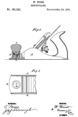
To all whom it may concern:
Be it known that I, GEORGE A. CLIFFORD, of Peabody, in the county of Essex, State of Massachusetts, have invented a certain new and useful Improvement in Planes, of which the following is a description sufficiently full, clear, and exact to enable any person skilled in the art or science to which said invention appertains to make and use the same, reference being had to the accompanying drawings, forming a part of this specification, in which —
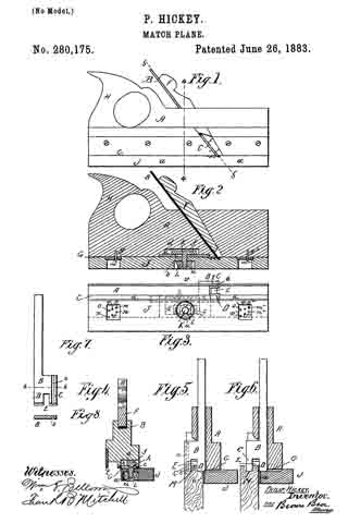
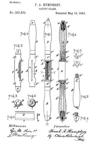
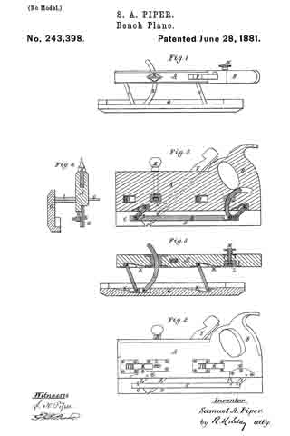
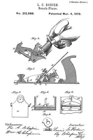
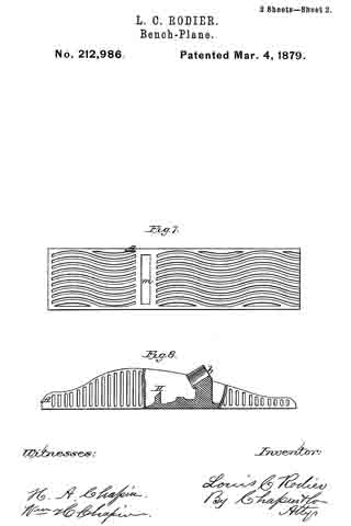
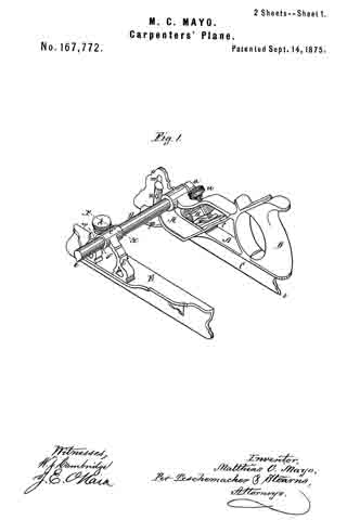
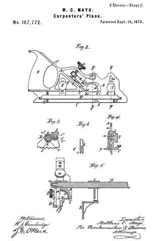
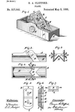
Figure 1 is an isometrical perspective view of my improved plane; Fig. 2, a vertical longitudinal section of the same; Fig. 3, a vertical transverse section; Fig. 4, a bottom plan view; Fig. 5, a front elevation of the iron and its stock detached from the body; Fig. 6, a vertical longitudinal section of the same, and Fig. 7 a vertical transverse section of the stock with the iron removed.
Like letters of reference indicate corresponding parts in the different figures of the drawings.
My invention relates to the class of planes known as “chamfer-planes;” and it consists in a novel construction and arrangements of the parts, as hereinafter more fully set forth and claimed, by which a more effective device of this character is produced than is now in ordinary use.
The nature and operation of the improvement will be readily understood by all conversant with such matters from the following explanation, its extreme simplicity rendering an elaborate description unnecessary.
In the drawings, A represents the body, B the stock, and C D the irons. The body is provided on its under side with a longitudinal V-shaped equilateral groove, E, running its entire length, and adapted to fit over or receive the corner or edge of the article to be chamfered or beveled. An inclined mortise, H, for receiving the stock, is formed in the body, and at the rear of this mortise, on either side, there is disposed a slide or rest, x, against which the stock presses. The stock B is rectangular in shape, and is provided on either side with a longitudinal dovetail groove, m. Each of its ends is inclined, as shown at f, one of them being rounded, as seen at i, and the other squared, as shown at v. The stock is provided with two irons, C D, disposed in a chamber or recess, J, which is cut in its face, as best seen in Figs. 1 and 6. The iron D is rounded on its cutting-edge to correspond with the rounded end i of the stock B, the iron C being squared on its cutting-edge to correspond with the square end v of said stock. A mouth, z, opens outwardly from the chamber J through either end of the stock B, the irons C D respectively protruding through these mouths and being adjustably secured to the stock by the screw-bolts K.
Passing through either side of the body A, opposite the mortise H, there is a bolt, r, provided at its inner end with a square head, t, adapted to fit the dovetail groove m in the stock B, the outer end of said bolt being screw-threaded and respectively provided with nuts N.
In the use of my improvement the stock B is inserted in the mortise H, with the heads t of the bolts r in the grooves m, where it may be secured in any desired position by turning in the nuts N. The lower iron or iron to be used is then properly adjusted and secured by its bolt K, the upper or idle iron being withdrawn into the chamber J, and also secured by its bolt K.
It will be obvious that by reversing the stock B either iron may be brought into use, and also that irons having any desired shape of cutting edge or edges conforming to the style of work to be done may be employed.
I do not confine myself to securing the stock in the body A by means of the bolts r and nuts N, as any other suitable means may be employed for this purpose.
Having thus explained my invention, what I claim is —
1. A bench-plane consisting of a body and an endwise-reversible stock carrying cutters, said stock being rounded at one end and square at the other end, substantially as described.
2. The combination, in a bench-plane, of a body, a stock adjustable therein provided with T-shaped grooves, and set-screws which pass through the sides of said body and take into nuts within said grooves, substantially as described.
3. The combination, in a bench-plane, of a body, a stock adjustable therein provided with T-shaped grooves, said stock being provided with clamping-bolts for securing the irons adjustably therein, and set-screws which pass through the sides of said body and take into nuts within said grooves, substantially as described.
GEORGE A. CLIFFORD.
Witnesses:
L. C. BRIGGS,
C. A. SHAW.