No. 20,855 – Spoke Shave (Leonard Bailey) (1858)


UNITED STATES PATENT OFFICE.
_________________
L. BAILEY, OF WINCHESTER, MASSACHUSETTS.
SPOKE-SHAVE.
_________________
Specification of Letters Patent No. 20,855, dated july 13, 1858.
_________________
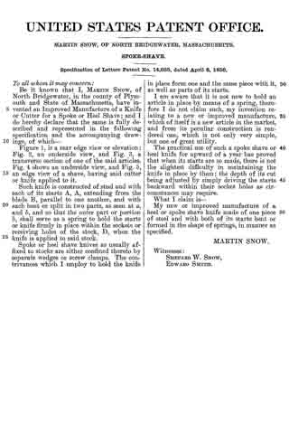
To all whom it may concern:
Be it known that I, LEONARD BAILEY, of Winchester, in the county of Middlesex and State of Massachusetts, have invented an Improved Spoke-Shave; and I do hereby declare that the same is fully described and represented in the following specification and the accompanying drawings, of which —
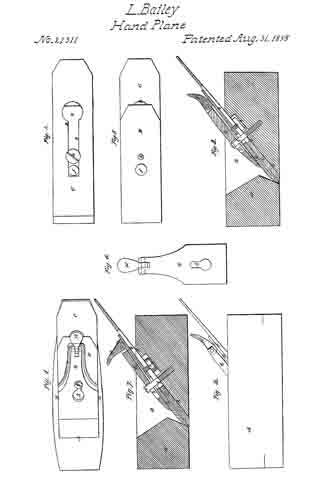
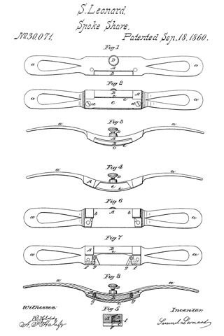
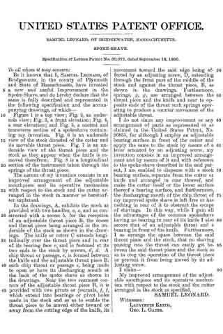
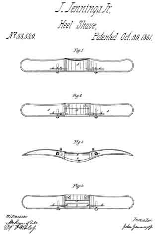
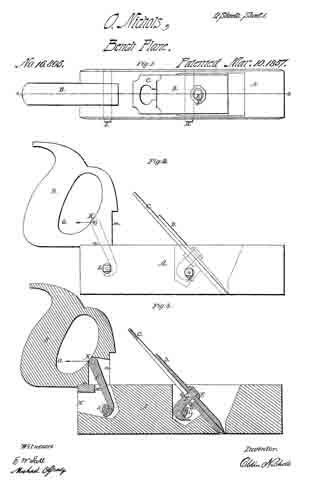
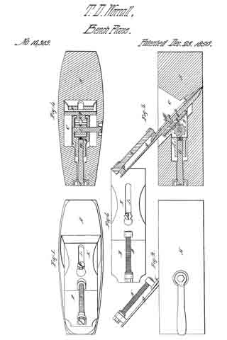
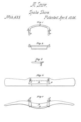
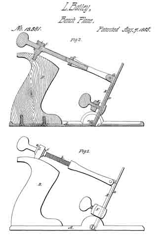
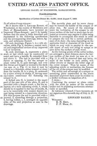
Figure 1, is a top view. Fig. 2, a bottom or underside view, and Fig. 3, a vertical central and transverse section of it. Fig. 4, is a. longitudinal section taken through the retracting spring and its protecting cavity or chamber. Fig. 5, is a top view of the stock without its appliances. Fig. 6, is an end view of the spoke shave.
The nature of my invention consists in an improved spoke shave constructed with its bearing surface in front of its cutter applied to the stock by means of a lever having an adjusting screw or its equivalent or an adjusting screw and a retracting spring so applied to it as to enable the said bearing surface to be moved either toward or away from the cutting edge of the cutter in order to diminish or enlarge the chip passage as well as to vary the angular position of the said bearing surface with respect to that in rear of the cutter, whereby advantages in the operation of the instrument are attained. Also, in an application and arrangement of a protecting cavity or chamber with respect to the lever and its retracting spring.
In the drawing A, denotes the body or the stock of the spoke shave, as constructed with two handles, a, a, and a throat or recess, B, for the reception of a cutter or plane iron B’, which is arranged on the seat or bottom of the throat and is confined thereto by means of a screw, c, which passes through a slot, d, formed in the iron and screws into the stock. The head of the screw laps over the edges of the slot.
The bearing surface of the stock is composed, not only of a stationary part, d’, in rear of the cutter B’, but a movable part, e, which is arranged in front of the cutter. This movable part is made on a lever C, which is shaped as shown in the drawings, and has a journal extending from each side of it, into the adjacent side of the throat such journal being shown in dotted lines in Fig. 1. Furthermore an adjusting screw, E, screws through the back part of the lever and against the seat of the throat of the stock or such screw may pass through the lever and screw into the stock and be so applied to the lever or have such shoulders or appliances that when the screw is turned in one direction it shall tilt the rear part of the lever one way or toward the stock, and when moved in the opposite direction produce a reverse movement of the said lever.
I prefer that the adjusting screw on one side of the journal should screw through the lever and against the seat and that the part of the lever which is on the opposite side of the journals should be provided with a retracting spring I, to be fastened to it and bear on the stock. Were this spring fastened at its middle to the top of the lever and made to extend across the same in such manner as to have its ends bear on the stock, the spring would be so exposed to shavings, as they might be expelled from the throat, that they would be liable to collect between it and the lever and by so doing effect, more or less, its correct action. In order to prevent this I form within and traversely through the lever, a cavity or chamber, g, which I make of a less diameter at its middle part, than it is at its ends or as shown in Fig. 4. This cavity or chamber receives the spring I, made of a piece of round steel wire, and to fit tightly at its middle part to the middle part of the cavity while the ends of the said spring rest on the stock as shown in Figs. 1 and 6. By means of the chamber or cavity surrounding the spring, the latter is protected from shavings which during the use of the shave might rise out of the throat and get between the spring and the lever were the spring not so protected.
By means of the above described mode of changing the width of the mouth of the shave, the thickness of its cut or of the shaving made by it when in use may be regulated, a spoke shave so made being found to operate in practice to great advantage.
I claim —
1. The improved spoke shave as constructed with its bearing surface in front of its cutter, applied to the stock by means of a lever having an adjusting screw or its equivalent, or a screw and a spring applied to it so as to enable the said bearing surface to be moved with respect to the cutter, and the bearing surface in rear thereof, substantially in manner as described.
2. I also claim the arrangement and application of a projecting cavity or chamber within the lever and to the spring thereof in manner and for the purpose as hereinbefore set forth.
In testimony whereof I have hereunto set my signature.
LEONARD BAILEY
Witnesses:
R. H. EDDY,
F. P. HALE, Jr.