No. 201,068 – Improvement In Bench-Planes (Harrison P. Taylor) (1878)

UNITED STATES PATENT OFFICE.
_________________
HARRISON P. TAYLOR, OF MINERVA, OHIO.
IMPROVEMENT IN BENCH-PLANES.
_________________
Specification forming part of Letters Patent No. 201,068, dated March 5, 1878; application filed September 7, 1877.
_________________
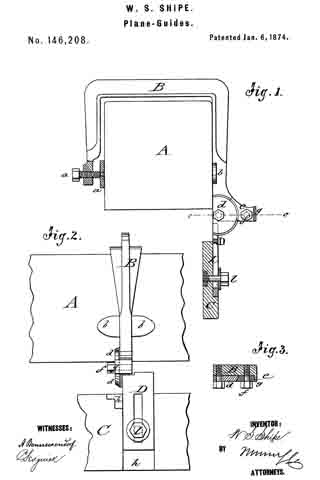
To all whom it may concern:
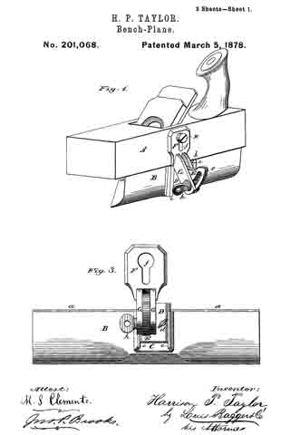
Be it known that I, HARRISON P. TAYLOR, of Minerva, in the county of Stark and State of Ohio, have invented certain new and useful Improvements in Bench-Planes; and I do hereby declare that the following is a full, clear, and enact description thereof, which will enable others skilled in the art to which it appertains to make and use the same, reference being had to the accompanying drawings, which form a part of this specification, and in which —
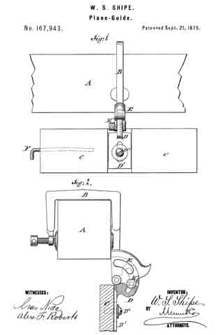
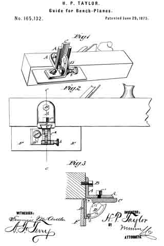
Figure 1 is a perspective view of a plane with my improved plane-guide attached to the side. Fig. 2 is a similar view, showing the guide-strip attached to the face of plane. Fig. 3 is a side elevation of the guide detached. Fig. 4. is an edge view of the same, and Fig. 5 is an end view.
Similar letters of reference indicate corresponding parts in all the figures.
My invention relates to guides for edge-planing; and consists in the construction of a reversible guide, which may be used either on the side or on the face of the plane, as circumstances shall render desirable, substantially as I shall now proceed more fully to describe, my present invention being an improvement on the invention for which Letters Patent of the United States No. 165,132 were granted to me on the 29th day of June, 1875.
In the drawings, A represents the plane, which may be of any suitable size and construction. The guide consists of a beveled strip of wood or metal, B, upon the beveled side or face of which is secured a metal plate, G, having turned-over parallel side flanges c c, by which a dovetailed slot or groove, b, is formed. In this groove slides a dovetailed plate, D, carrying a set-screw, d, by means of which it may be adjusted in any given position in relation to plate C. Secured at right angles upon plate C is a segment, E, which has a segmental slot, e, and the front edge of which is marked with a graduated scale. (See Fig. 4.)
F is the key-plate, which has a key-hole-shaped slot or mortise, f and is secured to the end of a slotted arm, G G’, pivoted at g to the point or center of the segment E, arms G G’ corresponding, therefore, to the radius of a circle whose center is at g, so that they will move freely on both sides of the slotted segment E. Through slot e passes a set or clamp screw, h, which unites arms G and G’, and by turning which these may be made to clamp the segment firmly, so as to remain immovably in position.
From the foregoing description, taken in connection with the two sheets of drawings, the manner of using my plane-guide will be readily understood. For ordinary use, it is secured upon the side of the plane, as shown in Fig. 1, so that only the narrow edge a of the guide-strip B shall bear against the face of the plane. To apply it to the plane, the bolt x is loosened a little, the large opening in the key-plate F is slipped over the bolt-head, after which the plate is pushed up against the bolt so as to bring the shank into the lower narrow part of the hole or mortise, when the bolt is again tightened, and the guide is in position ready for use. The angle of strip B is then regulated (according to the angle the edge is to have) by means of the clamp G G’, clamp-screw h, and the slotted and graded segment E, while vertical adjustment — that is, the distance between the bolt x upon which the guide is secured and the upper edge of the guide-strip — may be adjusted by means of the sliding plate D and set-screw d, so that my guide may be used on planes having different heights or distances between their side bolts and faces by a simple and easily effected adjustment of the guide.
If the plane-bit is dull in one place, or at one edge or side, the guide-strip B may be reversed, without detaching the adjusting mechanism from the plane, by simply loosening set-screw d, sliding plate C off of plate D, reversing the strip and plate, and sliding it on again from the opposite (thick) side of the strip, after which it is again secured in place by the set-screw d. When in this position (represented in Fig. 2) the strip will project over the face of the plane a width of about an inch, and covering the dulled part of the bit, so that full use may be had of its remaining exposed edge.
The manner of angular and vertical adjustment is, of course, precisely the same as that already described in explaining the adjustment of the guide when used as represented in Fig. 1.
This guide, consisting as it does, of few parts, is simple and durable in construction, will fit any plane, and can be produced at a small cost. It cannot give or spring while in use, but insures a true edge without any deviation from the proper angle, according to the set or adjustment of the guide at starting,
Having thus described my invention, I claim and desire to secure by Letters Patent of the United States —
l. The beveled guide-strip B, having grooved plate C, in combination with the reversible plate D and vertically-adjustable key-plate F, substantially as and for the purpose herein shown and specified.
2. The combination of the slotted, and vertically-adjustable key-plate F with the graduated segment E, provided with the reversible plate D, substantially as and for the purpose herein shown and described.
3 The combination of the reversible plate D, provided with the slotted and graduated segment E, with the beveled or wedge-shaped guide-strip B, substantially as and for the purpose herein shown and specified.
In testimony that I claim the foregoing as my own I have hereto affixed my signature in presence of two witnesses.
HARRISON P. TAYLOR.
Witnesses:
GEO. KRYDER,
JOHN L. GOWER.