No. 879,793 – Plane (Andro Nyland) (1908)

[paiddownloads id=”653″]879793


UNITED STATES PATENT OFFICE.

_________________

ANDRO NYLUND, OF DULUTH, MINNESOTA.

PLANE.

_________________

879,793. Specification of Letters Patent. Patented Feb. 18, 1908.
Application filed May 28, 1907. Serial No. 376,047.

_________________

To all whom it may concern:

Be it known that I, ANDRO NYLUND, a citizen of the United States, and a resident of Duluth, in the county of St. Louis and State of Minnesota, have invented a new and Improved Plane, of which the following is a full, clear, and exact description.

This invention relates to planes, and it is particularly useful with rabbet or dado planes.

The object of the invention is to provide a simple, strong and efficient plane, having adjustable means for limiting the depth to which the cut of the plane may proceed, and which is provided with means for easily adjusting the plane iron and for locking the same in position.

A further object of the invention is to provide a plane having guide blades at both sides thereof, which can be easily and quickly adjusted, and which has means for limiting the projection of the blades.

The invention consists in the construction and combination of parts to be more particularly described hereinafter and fully set forth in the claims.

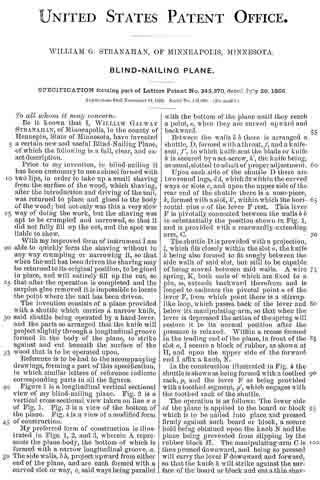
Reference is to be had to the accompanying drawings forming a part of this specification, in which similar characters of reference indicate corresponding parts in all the views, and in which Figure 1 is a side elevation of the plane; Fig. 2 is an elevation of the opposite side of the plane, showing parts broken away and in section 5 Fig. 3 is a vertical cross-section on the line 3–3 of Fig. 1; Fig. 4 is a vertical cross-section on the line 4–4 of Fig. 1; Fig. 5 is an enlarged view of a detail showing parts in cross section and parts broken away; and Fig. 6 is a plan view of a part of the plane.

Referring more particularly to the drawings, 1 represents the body of the plane, which may be of wood or any other suitable material. Secured to the body 1 is the sole-plate 2 extending the entire length of the tool. Side-plates 3 are secured to the sides of the body, and like the sole-plate 2 may be of steel or any other suitable material, preferably metal. The body 1 is cut away between the sides to form a plane iron recess 4. The recess 4 presents a flared opening 4a at the side, through which the shaving formed by the plane iron can leave the tool. The plane iron 5 is mounted in the recess 4 and presents a rack 6. A pinion 7 in mesh with the rack 6 is rotatably mounted in an extension 8 of the recess 4. The pinion 7 has a shank 9 extending through the side of the plate and provided with a wing 10, by means of which it may be operated. A locking-block 12 is secured upon the plane iron on the side opposite to the pinion 7. A set-screw 13 is mounted in a suitably threaded opening of the body and abuts against the block 12. The set-screw 13 is provided with a- wing 14 by means of which it may be operated to jam the plane iron in position through the block 12, which is carried in the recess 4 upon transverse pins 15 arranged in openings 16 of the block.

A recess 17 is formed in the body between the side plates 3, and connects with lateral guide grooves 18 formed at the sides of the body by the side-plates 3 which are cut away for this purpose. A threaded member 19 is arranged slidably in the recess 17 and is engaged by a screw pin 20. The screw pin 20 has a collar 21 seating against the upper part of the body, and a nut 22 in engagement with the inner wall of the recess to prevent the displacement of the screw pin, which has at its outer extremity a wing 23 by means of which it may be manually operated to adjust the member 19 within the recess. It will be understood that as the screw pin 20 is turned the member will move up or down within the recess. Guide blades 24 are slidably mounted in the guide grooves 18 and have slots 25. The guide blades 24 are adjustably secured to the member 19 by means of screws 26 arranged in the slots 25 and secured in suitable threaded openings in the member 19. The guide blades 24 have shoulders 27 adapted to engage with shoulders 28 formed at an edge of each slot, to limit the projection of the cutting point 29 of the blade from the groove. The guide blades are adapted to be projected a distance beyond the sole of the plane, equal at least to the projection of the plane eyes. In the operation of the plane in the usual manner, the guide blades form parallel grooves or guides exactly within and between which the plane iron follows and cuts the shaving.

A vertical guide-way 30 is formed within the body and has a lateral slot 31 extending through the side 3. A slidable member 32 comprising substantially a rod, is arranged within the guide-way 30 and has a lateral extension 33 in the slot 31. A gage member is secured to the extension 33 by means of a screw 35. The gage member 34 has a supplemental sole 36. The gage member may be adjusted at the side of the body by moving the member 32 up or down within the guide-way. A transverse pin 37 is arranged adjacent to the member 32 and has a wing 33 at the side, by means of which it may be operated. An eccentric cam groove 39 is formed in the pin 37. When the member 32 engages the cam groove at the greatest depth of the same the member is free to slide within the guide-way. When the pin 37 is rotated from this position the member 32 is jammed within the guide-way by the cam-like action of the groove. The pin 37 is provided with a second annular groove 40 with which a pin 41 carried by the body engages to prevent the lateral displacement of the adjusting pin 37. Aleaf spring 47 is arranged in the guide-way 30 and engages the member 32 to hold the same resiliently within the guide-way and to prevent lateral movement of the same. The gage 34 serves to determine and measure the depth oi the rabbet formed by the plane. A guide-plate 42 having slots 43 is adjustably mounted at the side of the plane opposite to the gage 34, by means of set-screws 44 arranged in the slots 43 and in suitable openings of the body. The guide-plate 42 extends the entire length of the plane and is adapted to be projected below the sole of the same to guide the tool at the edge of the work when a rabbet is being cut. A handle 45 is mounted by means of screws 46 at one side of the plane and serves for holding the tool when it is in operation.

Having thus described my invention I claim as new, and desire to secure by Letters Patent:

1. In a plane, a plane iron having a rack, and a pinion adapted to be manually controlled and operatively engaging with said rack, a block tapered toward the cutting edge of said iron and loosely mounted to engage the same, and a set screw adjustably engaging said block to lock said iron in position.

2. In a plane, a body having a guide-groove, a guide-blade mounted to slide in said groove, a movable member arranged to slide in the longitudinal direction of said groove and having an adjustable connection with said blade, and means for adjusting said member.

3. In a plane, a body having a recess, and a guide-groove communicating with said recess, a movable member in said recess, a guide-blade in said groove and having an adjustable connection with said member, and a screw-pin engaging with said member and controlling the same.

4. In a plane, a body having a recess, and a guide-groove communicating with said recess and presenting a shoulder, a movable member in said recess, a guide-blade in said groove and having an adjustable connection with said member, said guide-blade presenting a shoulder adapted to engage said shoulder of said guide-groove to limit the projection of said blade from said groove, and a screw-pin engaging with said member and controlling the same.

5. In a plane, a body having a recess and guide-grooves at opposite sides of said body and communicating with said recess, a movable member in said recess, guide-blades in said grooves and presenting slots, adjustable screws carried by said member and engaging said slots to secure said blades to said member, and a screw-pin operatively engaging said member and having collars engaging said body to prevent the longitudinal movement of said pin.

In testimony whereof I have signed my name to this specification in the presence of two subscribing witnesses.

ANDRO NYLUND.

Witnesses:
S. C. MILLER,
W. A. ANDERSON.

No. 820,639 – Plane (Andrew N. Gabrielson) (1906)

[paiddownloads id=”632″]820639


UNITED STATES PATENT OFFICE.

_________________

ANDREW N. GABRIELSON, OF MOUNT IRON , MINNESOTA.

PLANE.

_________________

820,639. Specification of Letters Patent. Patented May 15, 1906.
Application filed December 18, 1905. Serial No. 292,203.

_________________

To all whom it may concern:

Be it known that I, ANDREW N. GABRIELSON, a citizen of the United States, residing at Mount Iron, in the county of St. Louis, State of Minnesota, have invented certain new and useful Improvements in Planes; and I do hereby declare the following to be a full, clear, and exact description of the invention, such as will enable others skilled in the art to which it appertains to make and use the same.

This invention relates to planes, and more particularly to hand-planes, and has for its object to provide a plane which may be used either as a jack-plane or a smoothing-plane and which will be provided with guides arranged for movement into and out of position to lie against the working face of the board to insure even planing of the edges thereof.

Other objects and advantages will be apparent from the following description.

In the drawings forrning a portion of this specification, and in which like numerals of reference indicate similar parts in both views, Figure 1 is a side elevation of the present plane with the guides in the rabbets and showing them in lowered position in dotted lines. Fig. 2 is a transverse section on line 2 2 of Fig. 1, the guides being lowered.

Referring now to the drawings, the present invention comprises a body 5 and bits 6, provided with the usual bit-adjusting mechanism 7. The body 5 has longitudinal rabbets 5′ at its lower side angles, and communicating with each of these rabbets there are forward and rearward vertical threaded passages 8, in which are adjustably engaged set-screws 9, the lower ends of the set-screws being revolubly engaged in guides 10, which extend longitudinally of the body 5 and which are adapted to lie in the rabbets 5’. The arrangement is such that the set-screws may be operated to move the guides 10 into and out of the rabbets, and when both guides are in the rabbets the plane may be used in the ordinary manner. When the edge of a board is to be planed, one of the guides is lowered to rest against the working face of the board, and thus planing of the edge at right angles to the working face is assured.

Laterally-extending threaded passages 11 communicate with the passages 8 and open through the side faces of the body, and in these passages 11 there are engaged screws 12, which are operable to impinge against the set-screws 9 to hold the latter, with the guides, at different points of their movement. In their mutually-adjacent faces the guides have recesses 13, which receive the edge portions of the bit 6 when the guides are in the rabbets.

What is claimed is —

In a plane, the combination with a body having longitudinal rabbets at its lower side angles and having vertical threaded passages communicating with the rabbets, of set-screws engaged in the passages, guides connected with the lower ends of the set-screws for rotation of the latter with respect thereto, said set-screws being operable to move the guides into and out of the rabbets, and means for holding the set-screws with the guides at different points of their movement.

In testimony whereof I affix my signature in presence of two witnesses.

ANDREW N. GABRIELSON.

Witnesses:
VICTOR I. FRASER,
F. J. JOHNSON.

No. 584,002 – Plane-Guide (Erick Lindfors) (1897)

[paiddownloads id=”529″]584002


UNITED STATES PATENT OFFICE.

_________________

ERICK LINDFORS, OF MINNEAPOLIS, MINNESOTA.

PLANE-GUIDE.

_________________

SPECIFICATION forming part of Letters Patent No. 584,002, dated June 8, 1897.
Application filed May 7, 1895. Serial No. 548,413. (No model.)

_________________

To all whom it may concern:

Be it known that 1, ERICK LINDFORS, a citizen of the United States, residing in the city of Minneapolis, county of Hennepin and State of Minnesota, have invented a certain new and useful Improvement in Plane-Guides, of which the following is a specification.

My invention relates to means for guiding jointer-planes and in any other kinds of planes, and its object is to provide an adjustably-connected wing or guide whereby the plane may be used for squaring or beveling at different angles the surface operated upon.

In the accompanying drawings, illustrative of my improvements, there is shown in Figure 1 a plan view of the skeleton of a device embodying my improvements; and in Fig. 2 a transverse section of the same, showing by full and dotted lines different positions of the guiding member relative to the tool while being used for different purposes.

In such drawings a metallic or other suitable frame or stock for carrying a plane-iron is shown by the reference Fig. 1, and the slot in the sole through such iron or bit may be introduced, secured, and adjusted in the ordinary way is shown at 2. The stock shown is a skeleton metal one, but it may be of wood, and a handle (not shown) should of course be provided for operating the tool. These features may be of any usual or suitable construction, for they form no part of the present improvement and are referred to only for the purpose of showing the relationship of the improvement to a form of tool that is well known.

At the side of the tool is suitably hinged, as by means of a wire 3 or pintles, in sockets 4, a wing 5, which serves as the guide in the operation of the tool. This wing has formed on or attached to it an arm 6, on which is formed or to which is attached a suitably-curved extension 7, which may be round or of any suitable shape. These latter members 6 and 7 are arranged to pass through a suitable opening in the side of the stock and the arm 7 to pass through a guiding member 8, supported within the stock by a partition 9 or other suitable support within the body 1, and a set-screw 10 (or other regulating device) is provided for engaging the part 7 to hold it in place in the guide, so as to hold the guide-wing 5 in desired positions of adjustment. As illustrated, the arm 6 and its entension 7 are connected by a pivot 11, and the guide 8 for the part 7 is swiveled in the partition 9. By these means the wing can be turned from an upward to a downward position through an are of about a half-circle, and it may be held in adjustment at any intermediate point by the set-screw 10. The tool may be used in the ordinary way and for the usual purpose of dressing lumber when the wing 5 is in position shown by the full lines in the drawings or is turned upward from such position, and when turned downward, as indicated at a in Fig. 2, it will serve to guide the tool and direct its cutting, so as to form a bevel on the board that is being cut. It will be understood that the wing 5 may be placed either on the upper or side surface of the board to be dressed, depending upon the work desired to be done, so that the blade of the tool as it is advanced will out in a course determined by the angle of inclination of the adjustable member 5, and so by the desired adjustment of this member 5 the tool can be utilized to cut or smooth surfaces within a range of ninety degrees, and by suitable graduations supplied on the arm 7 the degrees of adjustment can be accurately determined and fixed.

Having described my invention, what I claim is —

In a plane, the combination with a stock having a slot in its side and a cavity in its interior, of a guide-wing hinged to the stock adjacent to the slot therein, the curved extension 7 pivotally secured at one of its ends on the guide-wing and entering the slot in the stock, the guide 8 swiveled on the interior of the stock, and having a transverse opening for the reception of the extension 7, and a set-screw to fixedly secure said extension, substantially as described.

ERICK LINDFORS.

Wlitnesses:
ANDREW LIDEN,
J. W. PETERSON.

No. 345,870 – Blind-Nailing Plane (William G. Stranahan) (1886)

[paiddownloads id=”412″]345870


UNITED STATES PATENT OFFICE.

_________________

WILLIAM G. STRANAHAN, OF MINNEAPOLIS, MINNESOTA.

BLIND-NAILING PLANE.

_________________

SPECIFICATION forming part of Letters Patent No. 345,870, dated July 20, 1886.
Application filed November 14, 1885. Serial No. 182,808. (No model.)

_________________

To all whom it may concern:

Be it known that I, WILLIAM GALWAY STRANAHAN, of Minneapolis, in the county of Hennepin, State of Minnesota, have invented a certain new and useful Blind-Nailing Plane, of which the following is a full, clear, and exact description.

Prior to my invention, in blind-nailing it has been customary to use a chisel formed with two lips, in order to take up a small shaving from the surface of the wood, which shaving, after the introduction and driving of the nail, was returned to place and glued to the body of the wood; but not only was this a very slow way of doing the work, but the shaving was apt to be crumpled and narrowed, so that it did not fully fill up the cut, and the spot was liable to show.

With my improved form of instrument I am able to quickly form the shaving without in any way crumpling or narrowing it, so that when the nail has been driven the shaving may be returned to its original position, to be glued in place, and will entirely fill up the cut, so that after the operation is completed and the surplus glue removed it is impossible to locate the point where the nail has been driven.

The invention consists of a plane provided with a shuttle which carries a narrow knife, said shuttle being operated by a hand-lever, and the parts so arranged that the knife will project slightly through a longitudinal groove formed in the body of the plane, to strike against and out beneath the surface of the wood that is to be operated upon.

Reference is to be had to the accompanying drawings, forming a part of this specification, in which similar letters of reference indicate corresponding parts in all the figures.

Figure 1 is a longitudinal vertical sectional view of my blind-nailing plane. Fig. 2 is a vertical cross-sectional view taken on line x x of Fig. 1. Fig. 3 is a view of the bottom of the plane. Fig. 4: is a view of a modified form of construction.

My preferred form of construction is illustrated in Figs. 1, 2, and 3, wherein A represents the plane-body, the bottom of which is formed with a narrow longitudinal groove, a. The side walls, b b, project upward from either end of the plane, and are each formed with a curved slot or way, c, said ways being parallel with the bottom of the plane until they reach a point, e, when they are curved upward and backward.

Between the walls b b there is arranged a shuttle, D, formed with a throat, f, and a knife-seat, f’, to which knife-seat the blade or knife h is secured by a set-screw, h’, the knife being, as usual , slotted to admit of proper adjustment.

Upon each side of the shuttle D there are two round lugs, d d, which fit within the curved ways or slots c, and upon the upper side of the rear end of the shuttle there is a nose-piece, k, formed with aslot, k’, within which the horizontal pins o of the lever F rest. This lever F is pivotally connected between the walls b b in substantially the position shown in Fig. 1, and is provided with a rearwardly-extending arm, C.

The shuttle D is provided with a projection, l, which fits closely within the slot a, the knife k being also formed to fit snugly between the side walls of said slot, but still to be capable of being moved between said walls. A wire spring, K, both ends of which are fixed to a pin, m, extends backward therefrom and is looped to embrace the pivotal point n of the lever F, from which point there is a stirrup-like loop, which passes back of the lever and below its manipulating-arm, so that when the lever is depressed the action of the spring will restore it to its normal position after the pressure is relaxed. Within a recess formed in the leading end of the plane, in front of the slot a, I secure a block of rubber, as shown at H, and upon the upper side of the forward end I affix a knob, N.

In the construction illustrated in Fig. 4 the shuttle shown as being formed with a toothed rack, p, and the lever F as being provided with a toothed segment, p’, which engages with the toothed rack of the shuttle.

The operation is as follows: The lower side of the plane is applied to the board or block which is to be nailed into place and pressed firmly against such board or block, a secure hold being obtained upon the knob N and the plane being prevented from slipping by the rubber block H. The manipulating-arm C is then pressed downward, and being so pressed will carry the lever F downward and forward, so that the knife h. will strike against the surface of the board or block and cut a thin shaving therefrom, which shaving will pass up through the throat f; but as the way c is parallel with the bottom of the plane the shaving will not be detached from the board, and as the lever-arm C is released it will be returned to the position shown in Fig. 1 by the action of the spring K; and as the knife k and the projection l of the shuttle D fit closely within the groove A the edges of the shaving will not be torn, nor will it be crumpled so as to be narrowed, and consequently, after the nail has been driven in the cut formed by the knife h, the shaving, when returned to place and glued within the cut, will completely fill it, and it will be almost impossible to discover where the cut was made. The upward motion of the lever F is limited by the pin i.

Having thus fully described my invention, what I claim as new, and desire to secure by Letters Patent, is —

1. The combination, with a plane-body formed with a longitudinal slot, a, of a shuttle carrying a knife, and an operating-lever, the shuttle working in the body with its knife extending into the slot a, substantially as described.

2. The combination, with a plane-body formed with a longitudinal slot, a, and side slots, c c, curved upward at their rear ends, of a shuttle carrying a knife and formed with lugs d d, working in the slots c c, and an operating-lever for reciprocating the knife in the slot a, substantially as described.

3. The combination, with a plane-body formed with a longitudinal slot, a, and side slots, c c, curved upward at their rear ends, of a shuttle carrying a knife and formed with lugs d d, an operating-lever, and a spring, substantially as described.

4. A blind-nailing plane in which the following elements are combined: a plane-body, A, formed with slot a and side slots, c c, curved upward at their rear ends, shuttle D, formed with lugs d d and a slot, k’, a knife, h, secured to the shuttle, a lever, F, manipulating-arrn C, and a spring, K, substantially as described.

5. A blind-nailing plane formed with a longitudinal groove, a, and side grooves, c c, a shuttle, D, formed with lugs d d and carrying a knife, as h, a lever, F, arm C, and block H, substantially as described.

WILLIAM G. STRANAHAN. [L. S.]

Witnesses:
JAMES F. STRANAHAN,
W. P. MORGAN.