No. 553,322 – Miter Or Bevel Plane (Justus A. Traut And Edmund A. Schade) (1896)
UNITED STATES PATENT OFFICE.
_________________
JUSTUS A. TRAUT AND EDMUND A. SCHADE, OF NEW BRITAIN, CONNECTICUT,
ASSIGNORS TO THE STANLEY RULE AND LEVEL COMPANY, OF SAME PLACE.
MITER OR BEVEL PLANE.
_________________
SPECIFICATION forming part of Letters Patent No. 553,322, dated January 21, 1896.
Application filed October 1, 1895. Serial No. 564,327. (No model.)
_________________
To all whom it may concern:
Be it known that we, JUSTUS A. TRAUT and EDMUND A. SCHADE, citizens of the (United States, residing at New Britain, in the county of Hartford and State of Connecticut, have invented certain new and useful Improvements in Miter or Bevel Planes, of which the following is a specification.
This invention relates to planes, more particularly of that class designated as “miter” or “bevel” planes; and the object of the invention is to provide an improved plane of this class more especially adapted for work on moldings and similar materials, whereby the same can be properly planed to permit the same to be joined with a miter or bevel joint, as desired.
The further object of the invention is to provide adjustable means in connection with and preferably embodied in the adjusting or gaging means whereby said adjustable means can be adjusted and held in engagement with the stock of the plane at whatever angle the gaging or adjusting means maybe positioned, to thereby constitute at all times a support for the material, whether the gaging means be adjusted in position adjacent to the plane-stock or not, and also to provide means in connection with such adjustable means whereby when the same is in engagement with the stock of the plane the projecting plane-iron will not strike the same, on the movement of the plane in either direction.
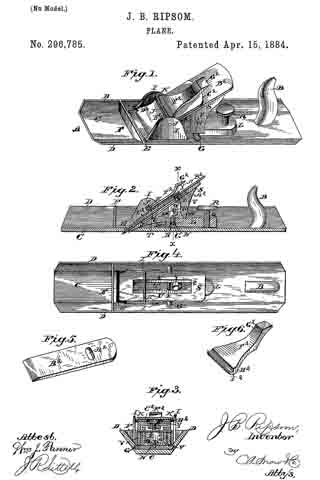
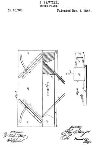
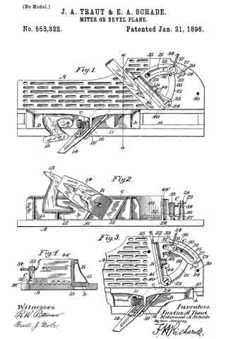
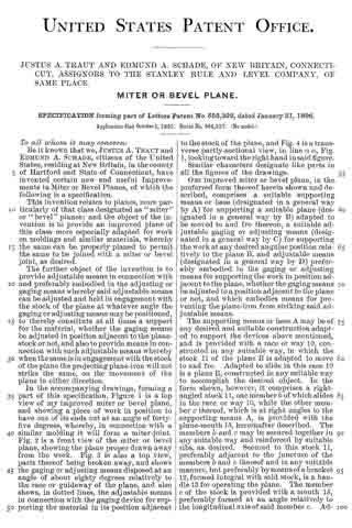
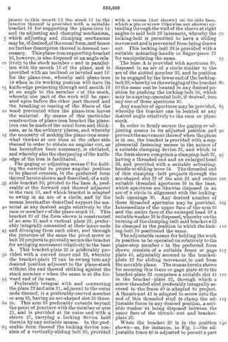
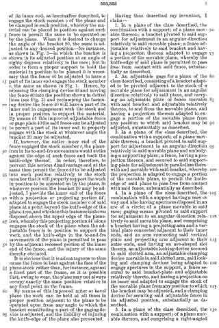
In the accompanying drawings, forming a part of this specification, Figure 1 is a top view of my improved miter or bevel plane, and showing a piece of work in position to have one of its ends cut at an angle of forty-five degrees, whereby, in connection with a similar molding it will form a miter-joint. Fig. 2 is a front view of the miter or bevel plane, showing the plane proper drawn away from the work. Fig. 3 is also a top view, parts thereof being broken away, and shows the gaging or adjusting means disposed at an angle of about eighty degrees relatively to the race or guideway of the plane, and also shows, in dotted lines, the adjustable means in connection with the gaging device for supporting the material in its position adjacent to the stock of the plane, and Fig. 4 is a transverse partly-sectional view, in line a a, Fig. 1, looking toward the right hand in said figure.
Similar characters designate like parts in all the figures of the drawings.
Our improved miter or bevel plane, in the preferred form thereof herein shown and described, comprises a suitable supporting means or base (designated in a general way by A) for supporting a suitable plane (designated in a general way by B) adapted to be moved to and fro thereon, a suitable adjustable gaging or adjusting means (designated in a general way by C) for supporting the work at any desired angular position relatively to the plane B, and adjustable means (designated in a general way by D) preferably embodied in the gaging or adjusting means for supporting the work in position adjacent to the plane, whether the gaging means be adjusted to a position adjacent to the plane or not, and which embodies means for preventing the plane-iron from striking said adjustable means.
The supporting means or base A may be of any desired and suitable construction adapted to support the devices above mentioned, and is provided with a race or way 10, constructed in any suitable way, in which the stock 11 of the plane B is adapted to move to and fro. Adapted to slide in this race 10 is a plane B, constructed in any suitable way to accomplish the desired object. In the form shown, however, it comprises a right-angled stock 11, one member b of which slides in the race or way 10, while the other member c thereof, which is at right angles to the supporting means A, is provided with the plane-mouth 15, hereinafter described. The members b and c may be secured together in any suitable way and reinforced by suitable ribs, as desired. Secured to this stock 11, preferably adjacent to the juncture of the members b and c thereof and in any suitable manner, but preferably by means of a bracket 12, formed integral with said stock, is a handle 13 for operating the plane. The member c of the stock is provided with a mouth 15, preferably formed at an angle relatively to the longitudinal axis of said member c. Adjacent to this mouth 15 the stock 11 in the interior thereof is provided with a suitable bracket 16 for supporting the plane-iron 14 and its adjusting and clamping mechanism, which adjusting and clamping mechanism may be, if desired, of the usual form, and hence no further description thereof is deemed neccessary. This plane-iron supporting-bracket 16, however, is also disposed at an angle relatively to the stock member c and in parallelism with the mouth 15 of the plane, and is provided with an inclined or beveled seat 16′ for the plane-iron, whereby said plane-iron 14 when in its working position will have its knife-edge projecting through said mouth 15 at an angle to the member c of the stock, whereby one part of the work will be operated upon before the other part thereof and the breaking or tearing of the fibers of the wood prevented when the plane-iron leaves the material. By means of this particular construction of plane-iron bracket the plane-iron can be made of the usual form and thickness, as in the ordinary planes, and whereby the necessity of making the plane-iron somewhat thicker at one than at the other side thereof in order to obtain an angular cut, as has heretofore been necessary, is obviated, and whereby also the sharpening of the knife-
edge of the iron is facilitated.
The gaging or adjusting means C for holding the material in proper angular position to be planed consists, in the preferred form thereof herein shown and described, of a suitable bracket 20, pivoted to the base A, preferably at the forward end thereof adjacent to the race 10, and which bracket is adapted to swing in an arc of a circle, and by the means hereinafter described support the material at any desired angle relatively to the race or member c of the plane-stock 11. This bracket 20 of the form shown is constructed of an arm 21 and a vertical plate 22, preferably integrally connected at their inner ends and diverging from each other, and through the juncture of the same the pivot screw or bolt 23 projects to pivotally secure the bracket for swinging movement relatively to the base A. This bracket-plate 22 is preferably provided with a curved inner end 24, whereby the bracket-plate 22 can be swung into any desired position adjacent to the plane-stock without the end thereof striking against the stock member c when the same is at the forward end of its race.
Preferably integral with and connecting the plate 22 and arm 21, adjacent to the outer ends thereof, is a preferably-curved member or arm 25, having an arc-shaped slot 26 therein. This arm 25 preferably extends beyond the point of juncture with the member or arm 21, and is provided at its outer end with a sleeve 27, carrying a locking device held therein by any suitable means. ln the preferable form thereof the locking device consists of a vertically-sliding bolt 28, provided with a recess (not shown) on its side face, which a pin or screw (likewise not shown) extending through the wall of the sleeve at right angles to said bolt 28 intersects, whereby the locking-bolt is permitted to have a sliding movement and is prevented from bein g drawn out. This locking-bolt 28 is provided with a suitable actuating-handle or finger-piece 20 for manipulating the same.
The base A is provided with apertures 30, disposed in an arc of a circle similar to the arc of the slotted member 25, and in position to be engaged by the lower end of the locking-bolt 28,whereby on the swinging of the bracket 20 the same can be located in any desired position by pushing the locking-bolt 28, which may be a spring-operated bolt, if desired, into any one of these apertures 30.
Any number of apertures may be provided, whereby the bracket can be located at any desired angle relatively to the race or plane stock.
In order to firmly secure the gaging or adjusting means in its adjusted position and prevent the movement thereof when the plane is in use, the bracket is provided with a supplemental fastening means in the nature of a suitable clamping device 31, and which in the form shown comprises a clamping-bolt 32, having a threaded end and an enlarged head 33, and provided with a suitable actuating-handle or sliding lever 34. The threaded end of this clamping-bolt projects through the arc-shaped slot 26 of the arm 25 and enters suitable threaded apertures 35 in the base, which apertures are likewise disposed in an arc of a circle in alignment with the locking-bolt openings 30. Any desired number of these threaded apertures may be provided. Intermediate of the upper face of the arm 25 and the under face of the enlarged head 33 a suitable washer 36 is disposed, whereby on the turning of the clamping-bolt said bracket will be clamped in the position in which the locking-bolt 28 positioned the same.
The adjustable means for holding the work in position to be operated on relatively to the plane-stop member c in the preferred form shown consists of a suitable fence or gage plate 40, adjustably secured to the bracket-plate 22 for sliding movement to and from the in movable plane. The means herein shown for securing this fence or gage plate 40 to the bracket-plate 22 comprises a suitable slot 41 in the bracket-plate 22, through which a screw-threaded stud preferably integrally secured to the fence 40 is adapted to project. A thumb-nut 43 is adapted to screw onto the end of this threaded stud to clamp the adjustable fence in any desired position, a suitable washer 44 being disposed between the inner face of the thumb-nut and bracket-plate 22.
When the bracket 20 is in the position shown — as, for instance, in Fig. 1 — the adjustable fence 40 is adjusted to permit a part of its inner end, as hereinafter described, to engage the stock member c of the plane and be clamped in such position, whereby the material can be placed in position against such fence to permit the same to be operated on by the plane. When it is desired to change the angle of the bracket 20, the same is adjusted to any desired position — for instance, as shown in Fig. 3 — in which the bracket is shown in its adjusted position at an angle of eighty degrees relatively to the race; but in order to form a proper support to hold the material in position to be planed it is necessary that the fence 40 be adjusted to have a part of its inner end engage the stock member c, the same as shown in Fig. 1. Hence, by releasing the clamping device 43 and moving the fence 40 into the position shown in dotted lines (see Fig. 3) and reclamping the fastening device the fence 40 will have a part of its inner end in engagement with the stock and in proper position to support the material. By means of this improved adjustable fence or gage plate 40 the said fence can be adjusted to permit a part of its inner end to properly engage with the stock at whatever angle the bracket 20 may be adjusted.
If, however, the entire inner end of the fence engaged the stock member c, the plane-iron in its to-and-fro movements would strike against the edge of such fence and hack the knife-edge thereof. In order, therefore, to prevent this serious disadvantage and at the same time permit the fence 40 to be adjusted into such position relatively to the stock member that it will properly support the work in position to be operated on by the plane, in whatever position the bracket 20 may be adjusted, I provide the inner end of the fence with a projection or projecting portion 44′, adapted to engage the stock member c of said plane at a point beyond the knife-edge of the plane-iron, and which in this instance is shown disposed above the upper edge of the plane-iron, whereby this projecting portion 44′ alone engages the stock of the plane when the adjustable fence is in position to support the work, and the knife-edge in the to-and-fro movements of the plane is permitted to pass by the adjacent recessed portion of the inner end of the fence, and the injury of the same thereby obviated.
It is obvious that it is advantageous to thus cause the fence to bear against the face of the plane-stock rather than, for instance, against a fixed part of the frame, as it is possible that, owing to wear, the plane may not always occupy exactly the same position relative to any lined point on the frame.
By means of this improved miter or bevel plane the work can be held at all times in proper position adjacent to the plane to be operated upon from any angle to which the bracket constituting a part of the gaging device is adjusted, and the liability of injuring the knife-edge of the plane also prevented.
Having thus described my invention, I claim —
1. In a plane of the class described, the combination with a support; of a plane movable thereon; a bracket pivoted to said support for adjustment in an angular direction relatively to said movable plane; a fence adjustable relatively to said bracket and having a projection thereon adapted to engage a portion of the movable plane, whereby the knife-edge of said plane is permitted to pass free from contact with said fence, substantially as described.
2. An adjustable gage for a plane of the class described, consisting of a bracket adapted to be pivoted adjacent to the stock of a movable plane for adjustment in an angular direction relatively to said plane, and carrying an adjustable plate or fence movable with said bracket and adjustable relatively thereto, to and from the movable plane, and having a projection thereon adapted to engage a portion of the movable plane from any position to which said bracket may be adjusted, substantially as described.
3. In a plane of the class described, the combination with a support; of a plane movable thereon; a bracket pivoted to said support for adjustment in an angular direction relatively to said movable plane and embodying a supporting plate; a fence, having a projection thereon, and secured to said supporting-plate for adjustment in parallelism therewith and movable with said bracket, whereby the projection is adapted to engage a portion of the movable plane, to permit the knife-edge of said plane to pass free from contact with said fence, substantially as described.
4. In a plane of the class described, the combination with a support havinga race or way-and also having apertures disposed in an arc of a circle; of a plane movable in said race; gaging means pivoted to said support for adjustment in an angular direction relatively to said movable plane, and comprising a bracket having a projecting arm and a vertical plate connected adjacent to their inner ends, and an arm connecting said vertical plate and projecting arm adjacent to their outer ends, and having an arc-shaped slot therein, an adj ustable locking device secured to said slotted arm, an adjustable clamping device movable in said slotted arm, said locking and clamping devices being adapted to engage apertures in the support, a fence secured to said bracket-plate and adjustable relatively thereto, and having a projection on its inner end adapted to engage the stock of the movable plane from any position to which the bracket may be adjusted, and a clamping device for securing said adjustable fence in its adjusted position, substantially as described.
5. In a plane of the class described, the combination with a support; of a plane movable thereon, and comprising a right-angled stock having a mouth therein disposed at an angle to the longitudinal axis of the plane; a plane-iron bracket secured to said stock, and also disposed at an angle to the longitudinal axis of the plane and in parallelism with the mouth of said plane; a plane-iron seated on said bracket and adapted to project through said mouth, whereby the knife-edge thereof will likewise be at an angle to the longitudinal axis of the plane; a bracket pivoted to said support for adjustment in an angular direction relatively to said movable plane; a fence adjustably connected to said bracket, and having a projection on its inner end adapted to engage a portion of the stock of the plane to permit the knife-edge thereof to pass free from contact with said fence, substantially as described.
6. In a plane of the class described, the combination with a support; of a plane movable thereon; a bracket pivoted to said support for adjustment in an angular direction relatively to said movable plane; a fence secured to said bracket for adjustment to and from the movable plane, and having a projection at its upper, inner end adapted to engage the plane-stock when said fence is adjusted into position relatively to said stock, whereby the knife-edge of the plane is permitted to pass below said projection and free from contact with the inner edge of the adjustable fence, substantially as described.
7. An adjustable gage for a plane of the class described, consisting of a bracket adapted to be pivoted adjacent to the stock of a movable plane, for adjustment in an angular direction relatively to said plane, and carrying an adjustable fence or plate movable with said bracket and adjustable relatively thereto, to and from the movable plane, and having a projection thereon adapted to engage a portion of the movable plane from any position to which said bracket may be adjusted; and means for clamping said bracket in its adjusted position, substantially as described.
8. An adjustable gage for a plane of the class described, consisting of a bracket adapted to be pivoted adjacent to the stock of a movable plane, for adjustment in an angular direction relatively to said plane; an adjustable fence or plate movable with said bracket and adjustable relatively thereto, to and from the movable plane, and having a projection thereon adapted to engage a portion of the movable plane from any position to which said bracket may be adjusted; means for adjustably clamping said fence to said bracket; and means for clamping said bracket in its adjusted position, substantially as described.
JUSTUS A. TRAUT.
EDMUND A. SCHADE.
Witnesses:
H. S. WALTER,
F. N. STANLEY.