No. 20,459 – Spokeshave (Charles H. Weston) (1858)

UNITED STATES PATENT OFFICE.
_________________
C. H. WESTON, OF NASHUA, NEW HAMPSHIRE.
SPOKESHAVE.
_________________
Specification of Letters Patent No. 20,459, dated June 1, 1858.
_________________
To all whom it may concern:
Be it known that I, C. H. WESTON, of Nashua, in the county of Hillsboro and State of New Harnpshire, have invented a new and useful Spokeshave; and I do hereby declare that the following is a full, clear, and exact description of the constriiction and operation of the same, reference being had to the accompanying drawings, forming a part of this specification, in which —
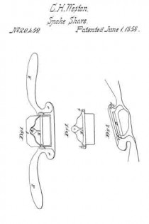
Figure 1, is a perspective view of the shave in readiness for operation, Fig. 2, is a view of the cap or holder; and Fig. 3, is a section of the handle with the cap and cutter removed.
Similar parts are indicated by the same letters in all the figures.
The nature of my invention consists, first, in confining the cutter by means of a thumb-screw and a single metal plate so constructed as to operate both as a lever-cap and holder; second, in making said cap, or holder, adjustable so as to work in combination with the cutter, when desired, as the top-iron of a double-iron plane; and third, in providing the handle with concave projections on either side of the cutter, to serve as rests for the fingers of the operator, when shoving the instrument from him.
To enable others, skilled in the art, to rnake and use my invention, I will new describe its construction and operation.
A A, Fig. 1, is a metallic handle, cast in one piece, and of any convenient size, like those in common use; D (Fig. 3) being the opening for the reception of the cutter and delivery of shavings.
B a, thin plate of metal, (a top view of which is given in Fig. 2) the underside being a little concave, and the lower edge beveled like that of a plane iron.
b b are arms projecting each side of B, the top sides of which (see Fig. 2) are furnished with little pins, or knobs, e, e.
a a are projecting arms, the under sides of which serve as fulcrums for the arms, b b, of the plate B.
1, 2, and 1, 2, are small holes (see Fig. 3) in the arms, a, a, into which the pins, or knobs, e, e, fit. When e e are placed in holes, 1, 1, the lower edge of plate, B, is carried down so near to the cutter. C, as to answer for the upper iron of a. double-iron plane, or shave, and when in 2, 2, it operates as simply a cap and holder.
G is a thumb-screw passing through a female screw in the plate B, until its point bears on the center, C, — which (as is evident from Fig. 1) will bring the arms b, b, against the fulcrum arms, a a, and the lower edge of B against the lower part of the cutter, C; by which means the cutter can be quickly and securely fastened.
d d are the concave projections in the frame, on both sides of the cutter (as seen in Fig. 1) to serve as rests for the fingers of the operator when shoving the instrument from him.
By loosening the thumb-screw, G, the cuttter can readily be adjusted so as to take any thickness of shaving, or be removed in order to be sharpened.
The method in which the shave can be used either as a single, or double-iron shave, at pleasure, by means of the adjustable cap, or holder B, has been explained above.
What I claim as my invention and desire to secure by Letters Patent, is
1. The plate, B, provided with arms, b, b so as to operate, substantially as set forth in conibination with the fulcrum arms, a, a, and thumb-screw G and projections d d, both as a cap and holder to the cutter, C.
2. Making the cap or holder, B, adjustable by means of knobs, e e, and holes, 1 2, or their equivalents, so that it may operate either as a simple cap and holder to the cutter, C, or in combination with it, as the upper iron of a double-iron plane, substantially as described.
CHARLES H. WESTON.
Winesses:
N. AMES,
O. C. SLEEPER.

