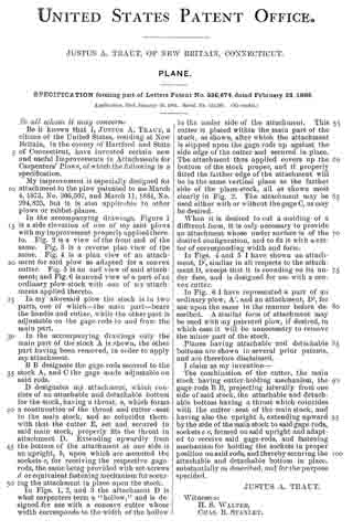
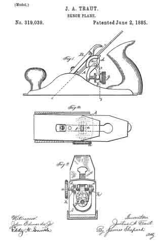
No. 342,235 – Plane (Justus A. Traut) (1886)

UNITED STATES PATENT OFFICE.
_________________
JUSTUS A. TRAUT, OF NEW BRITAIN, CONNECTICUT, ASSIGNOR TO
THE STANLEY RULE AND LEVEL COMPANY, OF SAME PLACE.
PLANE.
_________________
SPECIFICATION forming part of Letters Patent No. 342,235, dated May 18, 1886.
Application filed February 23, 1886. Serial No. 192,752. (No model.)
_________________
To all whom it may concern:
Be it known that I, JUSTUS A. TRAUT, a citizen of the United States, residing at New Britain, in the county of Hartford and State of Connecticut, have invented certain new and useful Improvements in Carpenters’ Plows, of which the following is a specification.
My invention relates to improvements in carpenters’ plows, and the object of my invention is to make a convertible “bull-nose”
and common plow so that said plow may be used for plowing a groove up to a shoulder — as, for instance, in grooving window-sash — or so that the plow may be used for the ordinary purposes.
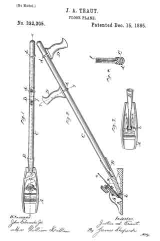
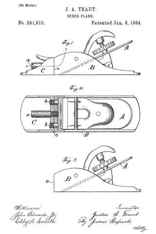
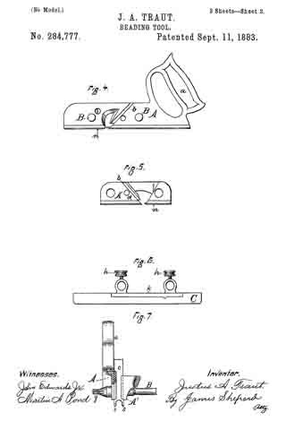
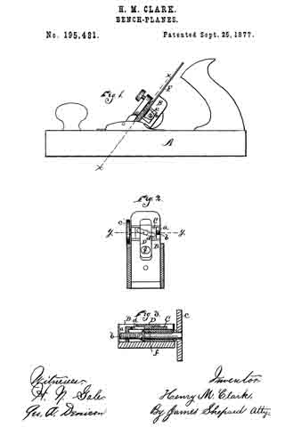
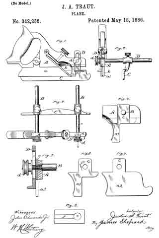
In the accompanying drawings, Figure 1 is an elevation of my plow, showing the rear side. Fig. 2 is a side elevation thereof, showing the front end. Fig. 3 is a plan view thereof. Fig. 4 is an enlarged view of a portion of my said plow. Fig. 5 is a vertical section, partly in elevation on the line x x of Fig. 3, of a part of said plow enlarged. Figs. 6 and 7 are side elevations enlarged of interchangeable tongues for the front end of the stock of my plow; and Fig. 8 is an edge view of a portion of a window-sash, showing a groove such as my plow is adapted to make when used as a bull-nose plow.
A designates the main portion of the stock; B B, the gage-rods secured thereto; and C the gage supported by said rods, all of which in their main features are of ordinary construction.
The main portion of the tongue or blade a, which is back of the cutter b and projects downward from the stock A, is secured there to in any ordinary manner. The portion of the tongue or blade which is forward of the cutter I form of two interchangeable tongues, a’ and a2, either of which in ay be attached to the stock. I make these interchangeable tongues attachable and detachable, so that one may be inserted for the other when desired, in the following manner: The under edge of the stock upon one side is provided with a vertical groove which cuts through the longitudinal groove in the bottom edge of the stock. This longitudinal groove is of a width which is designed to receive the upper edge of the interchangeable tongues a’ and a2, while the width of the vertical groove is such as to receive the tenon c, that projects from the upper edge of the interchangeable tongues a’ and a2. This tenon is provided with a threaded hole, which is adapted to receive the threaded shank at the end of the gage-rods, the hole through the stock A for the front gage-rod being bored smooth and large enough to admit said shank, as shown in Fig. 5. Thus it will be seen that slipping either one of the interchangeable tongues into place and screwing up the gagesrod firmly will hold said convertible tongue in proper position to form a continuation of that portion of the tongue or blade a which is in rear of the cutter, and that by unscrewing said gage-rod one convertible tongue may be removed for the insertion of the other. The ordinary depth-gage, D, is fitted to the vertical groove in the front end of the steel; A, and rests against the side of the tenon c. It is held-in position by means of the nut d.
When the plow is to be used for ordinary purposes, where there is plenty of room, the longer one, a2, of the interchangeable blades is attached to the stock; but when designed to be used in cramped places, so as to cut into a small hole or closely to a shoulder, the shorter one, a’, of the interchangeable tongues is attached, thereby converting the plow into what is termed a “bull-nose.” An example of such use is illustrated in Fig. 8, which shows the edge of a window-sash and the groove for the cord. In such work a hole, e, is bored in the sash and then the groove f is plowed out, the groove terminating within the hole. The length of the tongue a’ is less than the diameter of the hole, and consequently the whole of the groove f may be cut with the bull-nose plow. This cannot be done by a plow of the ordinary construction. In one sense of the word both portions of the blade or tongue of the stock have been made attachable and detachable. They are ordinarily formed of a separate piece from the body of the stock and set in a groove in the lower edge thereof, and held in position by rivets or screws; but, so far as I am aware, no one has ever heretofore provided a plow with interchangeable long and short tongues for attachment and detachment forward of the cutter for the purpose of making a convertble bull-nose and ordlnary plow.
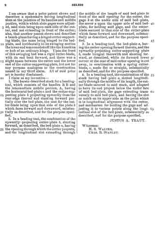
I claim as my invention —
The herein-described convertible bull-nose and ordinary plow, the same provided with interchangeable longer and shorter tongues for attachment to the forward part of the stock, substantially as described, and for the purpose specified.
JUSTUS A. TRAUT.
Witnesses:
H. S. WALTER,
F. N. STANLEY.