No. 701,471 – Bench-Plane Guide (George G. Dennis) (1902)

[paiddownloads id=”563″]701471


UNITED STATES PATENT OFFICE.

_________________

GEORGE G. DENNIS, OF MANCHESTER, NEW HAMPSHIRE, ASSIGNOR OF
ONE-HALF TO GEORGE A. DOLBER, OF MANCHESTER, NEW HAMPSHIRE.

BENCH-PLANE GUIDE.

_________________

SPECIFICATION forming part of Letters Patent No. 701,471, dated June 3, 1902.
Application filed September 9, 1901. Serial No. 74,761. (No model.)

_________________

To all whom it may concern:

Be it known that I GEORGE G. DENNIS a citizen of the United States, residing at Manchester, in the county of Hillsboro and State of New Hampshire, have invented certain new and useful Improvements in Bench-Plane Guides; and I do declare the following to be a full, clear, and exact description of the invention, such as will enable others skilled in the art to which it appertains to make and use the same, reference being had to the accompanying drawings, and to the letters of reference marked thereon, which form a part of this specification.

This invention relates to improvements in bench-plane guides and contemplates a simple and durable guide adapted to be readily attached to iron planes and which in use is very efficient and is not liable to disorder.

The nature of my invention will be readily comprehended, reference being had to the following detailed description and to the accompanying drawings, in which —

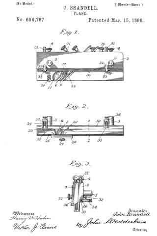
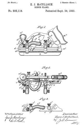
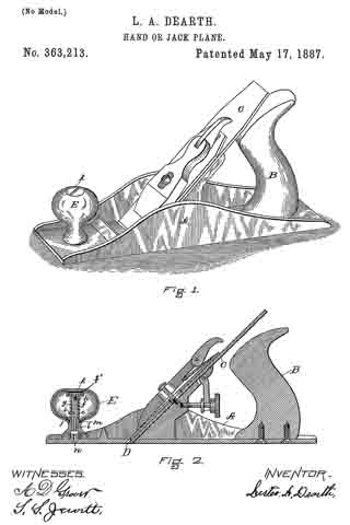
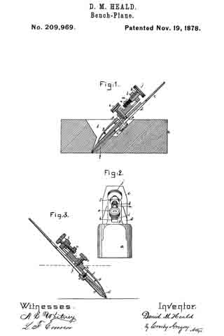
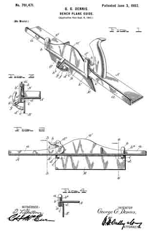
Figure 1 is a perspective view of my improved guide attached to a plane. Fig. 2 is a longitudinal sectional view of the plane and an elevation of the attached guide. Fig. 3 is a cross-sectional view on line 3 3 of Fig. 2. Fig. 4 is a cross-sectional view on line 4 4 of Fig. 2.

Referring to the drawings by letter, A denotes an iron bench-plane, which may be of the usual construction. At one side of the plane is the usual vertical flange a, having an intermediate enlargement a’.

My improved guide is comprised of a frame B, having at its ends vertical extensions b b’ and an intermediate outwardly-projecting lug b2. At the rear side and toward the ends of the frame B are ears c c, apertured to receive pins d d, which pivotally connect to the frame the adjustable guide-plate E. The guide plate has at its outer side and centrally a slotted and apertured ear c’, to which is pivotally connected by a pin d’ one end of an arm f The other end of the arm occupies a slot b3 in the lug b2, and g is a thumb-nut, which is screwed into the lug against the arm to maintain the adjustment of the guide-plate.

The extension b is provided at its upper end with a return bend b4, which hooks over the flange a. To the upper end of the extension b is pivotally secured, by means of a pin d2, a cam H, having a handle h.

In attaching the guide to the plane the frame is slid toward the rear until the forward rise of the flange enlargement wedges tightly between the hook b and the forward ear c The cam is then turned to tightly clamp the body of the plane between it and the rearward ear c The guide is thus easily and quickly attached and detached and when in place is firmly held against movement.

I claim as my invention —

A guide for flanged bench-planes consisting of a frame having at one end an extension terminating in an integral hook to engage the flange, an extension at the other end of the frame, a cam pivoted on the latter extension adapted to clamp the body of the plane, ears on the frame, a guide-plate pivoted to the ears, a pivoted arm on the guide-plate adjustable in a slot in a lug on the frame, and a set-screw passed through the lug against the arm for maintaining the adjustment.

In testimony whereof I affix my signature in presence of two witnesses.

GEORGE G. DENNIS.

Witnesses:
GEO. W. PRESCOTT,
FRED T. DUNLAP.

No. 600,767 – Plane (John Brandell) (1898)

[paiddownloads id=”535″]600767


UNITED STATES PATENT OFFICE.

_________________

JOHN BRANDELL, OF WALPOLE, NEW HAMPSHIRE.

PLANE.

_________________

SPECIFICATION forming part of Letters Patent No. 600,767, dated March 15, 1898.
Application filed August 5, 1897. Serial No. 647,180. (No model.)

_________________

To all whom it may concern:

Be it known that I, JOHN BRANDELL, of Walpole, in the county of Cheshire and State of New Hampshire, have invented certain new and useful Improvements in Planes; and I do hereby declare the following to be a full, clear, and exact description of the invention, such as will enable others skilled in the art to which it appertains to make and use the same.

This invention is an improvement in planes, and relates more especially to rabbeting-planes, the object of the same being to provide one that can be readily adjusted to increase and diminish the width of the rabbet or groove, and includes a guide for determining the depth of said groove and also certain devices for adjusting the bits, all as will be hereinafter fully set forth, and specifically pointed out in the appended claims.

In the accompanying drawings, forming part of this specification, Figure 1 is a side elevation of a rabbeting-plane constructed in accordance with my invention. Fig. 2 is a view looking at the lower edge of the plane. Fig. 3 is an end elevation. Fig. 4 is a detail view of one of the sections of the plane removed, including the parts carried thereby. Fig. 5 is a similar view of the other section of the plane. Fig. 6 is a side elevation of part of section 1, showing the gage-plate. Fig. 7 is an end view of gage-plate.

Referring more particularly to the drawings, 1 and 2 designate the two sections of the plane which form the sides thereof and are connected by pins 3, which extend from one section through openings therefor in the other section, the parts being held adjustable with respect to each other by the set-screws 4, carried by the section 2 and engaging the pins which project from the section 1. The pins are each provided with a scale, for a purpose hereinafter set forth.

The inner sides of the sections 1 and 2 of the plane are hollowed out, the section 1 presenting an inclined rib 5, upon which bears a bit 6, having teeth 7, by which it is connected to an elbow-lever 8, pivoted upon a bearing-pin 9, supported at one end by a bracket 10, while its other end is let into the section. The lower or cutting edge of the bit is adapted to be projected below the rib 5, the section having a lateral projection 11, the surface of which is curved, as shown, to guide the shavings out of the plane. The elbow-lever, which is connected to the bit, as hereinbefore described, is operated by a block 12, mounted upon a screw 13, bearing at its lower end in a post 14 and extending through the upper part of the section 1, where it is provided with a knob or milled wheel 15. The connection between the sliding block and lever is by means of a projection 16 on the block engaging the bifurcated end of the lever. The block is prevented from turning upon the screw by bearing against the inner side of the section 1, and it will be observed that when the said screw is turned the bit will be raised or lowered to adjust the same.

The bit is securely clamped in position after being adjusted by means of a clamp consisting of the parts 17 and 18, one of which bears against the upper part of the bit, while the other bears against the lower part thereof, the said clamp being pivoted upon a bearing-screw 19, supported at one end by a bracket 20. The parts or members of the clamp are forced upon the bit by means of a screw 21 engaging a threaded aperture in the projecting end of one part and bearing upon the projecting end of the other part, serving to force the latter directly against the bit, while drawing up upon the other part of the clamp in forcing its opposite end against the bit. It will be understood, of course, that before adjusting the bit the clamp is released, and by the particular construction and arrangement described a minute adjustment can be secured, the upper part of the bit being of a width to fit within the opening thereof and properly dispose the cutting edge with respect to the edge of the plane.

The section 2 of the plane carries mechanism for adjusting the bit which is similar in construction to that hereinbefore described, with the exception that the bit 22 is given further bearing-surfaces to prevent lateral movement, and to this end acasting 23 is secured to the rib 24, forming one of the bearings for said bit, the casting having projecting members supporting the pivot-pins of the mechanism. The bit carried by this section is so located with respect to the bit of the other section as to be located behind the same when the two sections are placed together.

By providing the plane with two sections movable to and from each other and having each section carry a bit the width of a groove to be cut by the plane can be increased or diminished by moving said sections to and from each other, the adjustment being held by thumb-screws, which engage the connecting-pins. In connection with the two bits each section is provided on its outer side with a cutting-blade 25, adjustable by having a slot through which a retaining-screw passes.

Upon one side of the plane is mounted a gage-plate 26, adjustable with respect to the edge of the plane by means of a thumb-screw 27 passing through a slot 28 therein and engaging a threaded aperture in the plane, gage-marks being provided, as shown, to indicate the extent of the adjustment, while the straight-edge of the gage-plate is maintained parallel with the edge of the plane by forming a rib 29 upon the inner side of the plate, which slides within a recess therefor in the plane. This gage-plate is for the purpose of determining the depth of the rabbet or groove.

I also provide the plane with a longitudinal guide-strip 30, connected to stems or pins 31, which slide within openings therefor in the side of the plane, the said guide-strip being held by thumb-screws 32, which engage the stems. When the guide-strip is projected below the bottom of the plane and held by the thumb-screws referred to, said strip may be adjusted inwardly under the body of the stock by screws carried by the strip and engaging threaded apertures in heads 33, formed at the outer ends of the pins, the screws rotatably engaging the strip at their inner ends and bearing at their opposite or outer ends in brackets 34, extending from the strip, the screws being held against longitudinal movement with respect to the strip and its brackets. When the guide-strip is extended below the edge of the plane, it will assist in forming a rabbet by bearing against the edge of the lumber or work. In forming a groove the guide-strip is slipped up out of the way, lying snugly against the longitudinal shoulder formed by the enlarged upper portion of the section 1 of the plane.

From the foregoing description, in connection with the accompanying drawings, it will be apparent that I provide a plane which is susceptible of numerous adjustments to not only vary the width of a rabbet or groove, but also to determine its depth, besides presenting a guide-strip which will be serviceable in preventing the plane cutting in when forming a rabbet.

Having thus described the invention, what is claimed as new is —

1. A rabbeting-plane comprising two sections, means for adjusting said sections to and from each other, and bits carried by each section, the bit of one section overlapping and being located in the rear of the bit of the other section, substantially as shown and for the purpose set forth.

2. A plane comprising two sections, pins carried by one section and extending through openings therefor in the other section, screws for holding the adjustment of the movable section, and bits carried by each section, the bit in one section being located in the rear of and overlapping the bit in the other section, substantially as shown and described.

3. A plane for the purpose set forth, comprising two sections adjustable to and from each other, overlapping bits carried by the sections and located one in front of the other, a gage-plate adjustable vertically upon one section, and a guide-strip attached to the other section, substantially as shown and described.

4. A plane comprising two sections adjustable to and from each other, overlapping bits carried by the sections and located one in front of the other, a gage-plate vertically adjustable upon one of the sections, a guide-strip connected to the other section by pins, and set-screws engaging the pins, substantially as shown and described.

In testimony whereof I have signed this specification in the presence of two subscribing witnesses.

JOHN BRANDELL.

Witnesses:
FRED PRENTISS,
CHARLES SLADE.

No. 505,119 – Bench-Plane (Eppie J. McCulloch) (1893)

[paiddownloads id=”493″]505119


UNITED STATES PATENT OFFICE.

_________________

EPPIE J. McCULLOCH, OF MANCHESTER, NEW HAMPSHIRE.

BENCH-PLANE.

_________________

SPECIFICATION forming part of Letters Patent No. 505,119, dated September 19, 1893.
Application filed March 15, 1893. Serial No. 466,010. (No model.)

_________________

To all whom it may concern:

Be it known that I, EPPIE J. McCULLOCH, of Manchester, county of Hillsborough, State of New Hampshire, have invented an Improvement in Bench-Planes, of which the following description, in connection with the accompanying drawings, is a specification, like letters on the drawings representing like parts.

My invention relates to a bench plane and is intended as an improvement on a plane of the kind shown in Letters Patent No. 294,825, dated March 11, 1884, to which reference may be had, the object of the present invention being to enable the plane to be used for moldings and a variety of similar kinds of work which cannot be performed by the plane shown and described in the said patent. The plane shown in said patent, to which the present invention may be applied, comprises a body portion or stock made in two parts which are adjustable toward and from one another to vary the width of the stock of the plane, one of said parts which may be called the main stock or body of the plane being provided with suitable handles to operate the same, and also being provided with laterally projecting rods or pins upon which the other portion of the body, or auxiliary stock, is supported, being made adjustable upon said pins toward and from the main stock so as to vary and adjust the width of the body of the plane. The said pins also support an edge gage or fence which regulates the distance of the cut from the edge of the board or piece of material that is being planed. These parts are all shown in the before mentioned patent in which the main and auxiliary stocks are described as made of cast metal; and as shown in the said former patent they have blades rigidly and permanently secured to them by rivets or otherwise which blades run upon the surface of the wood being planed and govern the depth of each cut like the stock or body of an ordinary plane. The main stock is provided with a suitable clamp to hold the cutter or plane iron, and in the plane shown in the before mentioned patent the blade of the auxiliary stock necessarily has its lower edge or sole always on the same level as the lower edge or sole of the main portion of the stock.

The present invention consists mainly in making the sole portion of the auxiliary stock vertically as well as laterally adjustable with relation to the main stock thus adapting the plane for use with an iron or cutter having a curved or irregularly formed cutting edge, the auxiliary stock being adjusted laterally to support or co-operate with the said cutter by giving the requisite width to the body or stock of the plane, and the blade portion of the auxiliary stock being also adjustable in a plane parallel with the main stock and in line with the slope of the cutter or iron so that its lower edge may be brought to the proper height with relation to the adjacent portion of the cutter to properly co-operate therewith in governing the depth of the cut. In other words while the sole portion of the stock of an ordinary molding plane is commonly shaped to correspond with the shape of the edge of the iron, the plane forming the subject of the present invention has what may be regarded as a skeleton stock having but two lines of bearing upon the surface being planed, and the adjustments provided for by this invention enable the said bearing lines to be brought in proper position with relation to the cutter whatever the shape of its cutting edge may be.

Figure 1 is a side elevation of a plane embodying this invention; Fig. 2 a plan view thereof; Fig. 3 a side elevation of the body portion of the auxiliary stock detached; Fig. 4 a side elevation similar to Fig. 1, but with the gage removed; Fig. 5 a side elevation of the blade of the auxiliary stock detached, and Fig. 6 a transverse section on the broken line x6–x, Fig. 4.

The main portion aof the stock having the handles a2 and the blade or sole piece a3, the iron or cutter clamp a4 and the lateral rods a5, as well as the gage or fence b supported on said rods a5, may be of any suitable or usual construction, being herein shown as the same as in the bench plane shown in Letters Patent No. 294,825, before mentioned. The body portion c of the auxiliary stock may also be the same as in said patent except as to the means for connecting it with the blade or sole piece d, of said auxiliary stock, the said body portion being provided with sockets c2 to engage with the lateral rods a5 upon which the said auxiliary stock is adjustable laterally toward and from the main portion of the stock as in the patent before referred to, being secured in adjusted position thereon by suitable clamping screws c3. The said auxiliary stock has a suitable recess to accommodate the iron or cutter e and the portions at the front and rear of the cutter recess are connected by a lateral arch c4 which affords a free opening for the escape of shavings. Instead of having the blade or sole piece of the auxiliary stock made in two pieces each riveted or rigidly fastened to the body portion, one at the front and the other at the rear of the cutter recess, as in the before mentioned patent, so that nothing but lateral adjustability is provided for the sole portion of the auxiliary stock with relation to that of the main stock, the said blade or sole portion d is in accordance with the present invention preferably made in a single piece as best shown in Fig. 5, having a suitable recess d2 to accommodate the iron e and permit the escape of the shavings; or in other words the portions of said blade that are at the front and rear of the cutter or iron are connected by a portion d3 that extends over the top of the iron and the space in front of it. The said blade d is adjustably connected with the auxiliary portion c of the stock so that the lower edge of the said blade, forming the sole of the auxiliary stock, may be adjusted up and down with relation to the sole portion or blade of the main stock, as may be required to bring it to the proper relation to the cutter or iron when the edge of the latter is of such shape (as for example in the one shown in Fig. 6) that the portion of its edge which is nearest to the auxiliary stock must be at a different level from the edge of the blade a3 of the main stock in order to co-operate properly with the cutter. It is necessary for the proper co-operation of the blade d and the cutter e that the up and down adjustment of the blade d should be in line with the inclined cutter, and to properly provide for this the blade d is provided with slots d4 which embrace the lateral pins a5 of the main stock, while permitting the blade d to move up and down diagonally with relation thereto, and the body portion c of the auxiliary stock is provided with similarly inclined slots c5 to engage with fastening devices shown as clamping screws f extending into suitable holes d5 in the blade d. Thus by loosening the screws f the blade d may be slid up and down in line with the cutter e until its lower edge or sole portion is brought to the proper height to co-operate properly with the adjacent portion of the cutter so as to afford an additional or auxiliary support besides that afforded by the blade a3 of the main stock to regulate the depth of the cut and to guide the plane along the material being planed. The amount of up and down adjustment may be increased beyond the length of the slot c5 in the body of the auxiliary stock by having two or more suitably threaded screw holes d5 at different levels as shown in Fig. 5. By this construction the lower edge or sole portion of the blade of the auxiliary stock may be adjusted to any desired position both laterally and vertically with relation to the lower edge of the blade of the main stock, and the two thus constitute a universally adjustable stock which may be used with irons or cutters of any width and any shape of cutting edge within the limits commonly required for cutters having other than straight edges, thus greatly increasing the capacity of the tool over that of one in which there is no vertical adjustment of one portion of the stock relative to the other, so that it is in fact adjustable in width only.

I claim-

l. The combination of the main stock having a blade fixed thereon with an auxiliary stock laterally adjustable with relation to said main stock, and a blade supported on said auxiliary stock and vertically adjustable thereon, substantially as and for the purpose described.

2. The combination of the main stock having a blade fixed thereon and lateral rods or pins, with an auxiliary stock adjustably supported on said rods, a blade connected with the said auxiliary stock having slots parallel with the iron or cutter of the plane embracing the rods, and means for fastening the said blade at different heights on said auxiliary stock, substantially as described.

3. The combination of the main stock, its blade, and rods projecting laterally from said stock; with the auxiliary stock adjustably supported on said rods and provided with slots c5 parallel with the iron or cutter of the plane, the blade d provided with a recess for the cutter, and having slots d4 parallel with the cutter embracing the rods of the main stock, and clamping screws f extending through the slots of the auxiliary stock, substantially as and for the purpose described.

In testimony whereof I have signed my name to this specification in the presence of two subscribing witnesses.

EPPIE J. McCULLOCH.

Witnesses:
CHAS. E. COCHRAN,
P. J. O’DONNELL.

No. 363,213 – Hand Or Jack Plane (Lester A. Dearth) (1887)

[paiddownloads id=”422″]363213


UNITED STATES PATENT OFFICE.

_________________

LESTER A. DEARTH, OF LACONIA, NEW HAMPSHIRE.

HAND OR JACK PLANE.

_________________

SPECIFICATION forming part of Letters Patent No. 363,213, dated May 17, 1887.
Application filed March 25, 1887. Serial No. 232,399. (No model.)

_________________

To all whom it may concern:

Be it known that I, LESTER A. DEARTH, of Laconia, in the county of Belknap and State of New Hampshire, have invented certain new and useful Improvements in Hand or Jack Planes, of which the following is a specification.

My invention relates to jack or hand planes, and has for its object to provide improvements in devices of that kind whereby the sole of the plane may be oiled (as is necessary in some classes of work) during the operation of smoothing or planing lumber therewith, and without the necessity of stopping work and employing a device separate from the plane itself for that purpose.

As is well known to carpenters, joiners, and others skilled in arts requiring the use of planes, it is essential in many kinds of work to oil the sole of the plane, and in instances where this thing is necessarily frequent much time is consumed thereby, as well as annoyance occasioned to the workman.

In carrying out my invention I utilize the knob secured to the upper face of the stock just in front of the slot provided for the escape of shavings as an oil-reservoir, in addition to its present uses, and combine means with said knob whereby the workman can from time to time, and while using the plane in the ordinary manner, supply oil to the sole thereof as may be needed.

I will now proceed to describe my invention, so that others may be able to make and use the same, reference being had to the accompanying drawings, and to the letters of reference marked thereon, forming a part of this specification, the same letters indicating the same parts wherever they occur, and the invention being particularly pointed out in the claims hereunto appended.

Of the drawings, Figure 1 represents a perspective view of a plane having my improvements applied thereto. Fig. 2 is a longitudinal vertical section thereof.

A indicates the plane-stock, provided with the usual handle, B, and cutting iron or tool C, adjustably secured to operate in the slot D, provided for that purpose and for the escape of shavings.

E represents the knob applied to planes as new commonly constructed, which knob is attached to the stock just in front of slot D. I construct knob E of metal or other suitable material and make it hollow, as represented in Fig. 2, providing the interior with a short tube, e, extending up from a central point at the bottom thereof, and form a hole of desired size in the top over tube e, the hollow of which latter feature extends through the bottom of the cup.

f represents a stem adapted to fit closely in tube e and to slide thereon, a spiral spring, g, surrounding said stem above tube e, and bearing at its lower end on the upper end of said tube and pressing at its upper end against a pin, h, extending through the stem, whereby the stem f is pressed upward in the tube, pin i, extending from the stern through a slot, j, in the tube, serving to limit both the upward and downward movement of the stem.

k represents a plug constructed to closely fit and slide in the hole formed in the upper end of the knob, as aforesaid, and adapted to be screwed into the upperend of stem f, or otherwise connected therewith, which plug serves both as a stopple to the hollow knob and affords means for gaining access to the interior thereof and as a contrivance whereby stem f may be depressed against the tension of spring g, operating as hereinabove explained.

f’ represents a packing of any suitable character arranged in a groove formed in plug k, or between two disks comprising the same, whereby the plug may be made to fit the hole in which it works in an oil and air tight manner. A small hole or bore, l, is made in stem f which hole extends vertically upward for a short distance from the lower end thereof, and then horizontally outward through the side of the stem, and a hole, m, is formed through the side of tube e, at the lower end thereof, constituting a valve, all as clearly represented in Fig. 2, the construction and arrangeinent of these last mentioned features being such as that when stem f is depressed by bearing on plug k bore l will be brought into range with hole m, and oil with which it is designed to fill knob E (made into a cup, as explained) will flow through said bore and down through a hole, n, formed in the stock to the sole of the plane — in the present instance shown to be just ahead of the cutting-tool.

The manner of using the invention will now be readily understood. The knob being filled with oil and the parts being arranged in position, as shown, the operator from time to time, as it may be necessary to oil the plane, as aforesaid, and without stopping his work, depresses stem f for a moment by pressing a thumb or finger thereon, releasing a drop or so of oil, which runs down through hole n, in the stock to the proper point on the sole of the plane.

By the means explained a material amount of time is saved to the workman, and by utilizing the knob common to nearly all classes or kinds of planes my invention is made cheap of construction and ready of application, as well as convenient in use.

Although I have been particular to describe the precise form and arrangement of the parts as here comprising my improvements, it is obvious that these may be varied within the limits of mechanical skill without departing from the nature or spirit of my invention.

Having thus described my invention, what I claim is —

1. In a plane, the combination, with the stock, of the knob thereon, made hollow or formed as an oil-cup, a valve in said knob or cup, and a spring-pressed stem or plug extending to the exterior of the knob, whereby the valve may be operated to release oil from the cup to oil the sole of the plane, as set forth.

2. In a plane, the combination. with the stock, of the knob thereon, made hollow or formed as an oil-cup and provided with the tube e, having hole m, and spring-pressed stem, f fitted to slide in said tube and provided with bore or hole l, substantially as set forth.

In testimony whereof I have signed my name to this specification, in the presence of two subscribing witnesses, this 19th day of March, 1887.

LESTER A. DEARTH.

Witnesses:
STEPHEN S. JEWETT,
S. E. BLACKSTONE.

No. 213,104 – Improvement In Lubricators (Edward F. Gordon) (1879)

[paiddownloads id=”301″]213104


UNITED STATES PATENT OFFICE.

_________________

EDWARD F. GORDON, OF CONCORD, NEW HAMPSHIRE, ASSIGNOR TO HIMSELF AND JOHN A. WHITE, OF SAME PLACE.

IMPROVEMENT IN LUBRICATORS.

_________________

Specification forming part of Letters Patent No. 213,104, dated March 11, 1879; application filed January 17, 1878.

_________________

To all whom it may concern:

Be it known that I, EDWARD F. GORDON, of Concord, in the county of Merrimack and State of New Hampshire, have invented a new and Improved Lubricator, of which the following is a specification:

Figure 1 is a side elevation, partly in section, of a plane having my improved lubricating device attached. Fig. 2 is a face view of the same. Fig. 3 is a plan view of a portion of a planer-bed containing my improvement. Fig. 4 is a transverse section taken on line x x in Fig. 3.

My invention relates to lubricators for hand-planes and the beds of planers, molding and scraping machines, or for other metallic surfaces requiring lubrication.

The invention consists in holes or cavities formed in the surface to be lubricated, said cavities being filled with wood or other unyielding porous material saturated with oil. The cavities are either wholly filled with wood or partly filled, so as to leave a chamber for containing oil.

This improvement is especially designed for lubricating metallic surfaces that are moved over wood surfaces, or over which wood surfaces are moved, in the processes of wood-working.

Referring to the drawings, A is an ordinary iron hand smoothing-plane, in the face of which a recess or cavity, b, is formed, into which is driven a piece of wood or other suitable porous material, c, which partly fills it, leaving the chamber c’ for containing oil. The grain of the wood runs at right angles to the face of the plane, so that the capillary tubes of the wood may draw from the oil-chamber a suflicient quantity of oil to constantly lubricate the face of the plane or the surface upon which the plane is moved, thereby obviating the sticking and friction which are common to metallic planes. The upper wall of the oil-chamber is apertured and provided with a screw-plug, d, for the purpose of filling.

In Figs. 3 and 4, B represents a portion of the bed or presser-bar of a planing, sticking, or scraping machine, in which there is an oil-chamber, C. In the upper surface of the bed there are slots e, that communicate with the oil-chamber C. In these slots pieces of wood f are driven, so that the grain is at right angles to the face of the bed, and their upper ends are even with the face of the bed, while their lower ends extend downward and dip into the oil contained by the chamber C. The oil-chamber is provided with a filling-aperture, g, which is closed by a screw-plug, h.

In some cases the oil-saturated wooden plugs or pieces may entirely fill the cavities in the surface to which the lubricator is applied, as the wood will contain a sufficient quantity of oil to lubricate the surface for a considerable time.

I do not limit or confine my improvement to any particular form or proportions, nor to its application to any special tool or machine, as it may he made in various forms, and is applicable to tools and machines of every sort in which wood is moved in contact with a metallic surface, or the metallic surface is moved in contact with the wood, in the processes of wood-working. It may also be applied with advantage to metal-working machines and to metal surfaces working in contact.

I am aware that it is not new to fill recesses in the faces of planers with wood or soap-stone and without any lubricant; also, that it is not new to use a reservoir filled with oil that is fed by a wick or leather conductor; but the latter soon exhausts the oil and soils the stock that is being worked. Mine, on the contrary, always presents a hard, smooth surface, and feeds just a sufficient trace of oil to lubricate without soiling the stock; hence,

What I claim is —

The combination, in wood-working machinery, of the oil-reservoir b and the wooden plug c, the latter having its grain at right angles to the working-face of the planer, scraper, or molder, as shown and described.

EDWARD F. GORDON.

Witnesses:
GEORGE H. MILLS,
CHAS. H. BUXTON.

No. 209,969 – Improvement In Bench-Planes (Daniel M. Heald) (1878)

[paiddownloads id=”296″]209969


UNITED STATES PATENT OFFICE.

_________________

DANIEL M. HEALD, OF MILFORD, NEW HAMPSHIRE.

IMPROVEMENT IN BENCH-PLANES.

_________________

Specification forming part of Letters Patent No. 209,969, dated November 19, 1878; application filed April 22, 1878.

_________________

To all whom it may concern:

Be it known that I, D. MILTON HEALD, of Milford, county of Hillsborough, State of New Hampshire, have invented an Improvement in Planes, of which the following is a specification:

This invention relates to improvements in planes, and has reference more especially to the method and means of supporting and adjusting the plane-iron in the throat, the invention being applicable to both wood and metal planes.

The cap, connected, as usual, with the plane-iron, is provided with a recess to receive the end of a cap-screw carried by a slide made adjustable by means of an adjusting-screw in guideways of a plate, f, pivoted within the body of the plane, so that as the slide is moved by the adjusting-screw the plane-iron and cap are moved longitudinally in the throat.

Figure 1 represents, in longitudinal vertical section, a plane provided with my improvements; Fig. 2, a front-end view thereof. Fig. 3 represents a modidcation hereinafter referred to.

As shown in this instance of my invention, the body a of the plane is supposed to be of wood and to be provided with a throat, b, extended therethrough in the usual manner.
The plane-iron c and its cap d are adjustably connected by means of the screw e, as in other planes.

The plane-iron holder f, preferably made of cast metal and pivoted to the body of the plane at g, has formed in it a guide slot or way, h, to receive a slide, i, which is made longitudinally adjustable therein by means of an adjusting-screw, j, preferably a compound screw, as shown in Figs. 1 and 2, it being composed of a coarse-threaded portion, k, fiitted to a lug, l, of the iron holder f, and of a finer-threaded portion, m, fitted to a lug, n, of the slide i. This slide i is provided with a cap-screw, o, having at its end a tenon, p, which enters a recess in the cap d, there being a shoulder on the screw a short distance per face of the cap and hold it and the plane-iron down in contact with the portion q of the body of the plane within the throat.

When the screw o is turned so that the tenon p enters the recess in the cap, it is obvious if the compound screw be turned that it will act upon the slide i and move it in the slot of the holder f and move with it the plane-iron and cap to regulate the degree of their projection below the face of the plane.

It is obvious that the end of screw o might be recessed to receive a tenon projecting from the cap.

By providing the screw j with threads of different pitch its power is increased. Such screw takes the place of the lever or cam commonly used in other adjustable planes.

The compound screw and cap-screw being located above the iron enables it to be more readily adjusted than can be the irons of other planes wherein the adjusting devices are below the iron.

The screw j might be provided with a thread of uniform pitch; but threads of two pitches are preferable. This compound screw is lntended to operate on the principle of the well-known “Hunter screw.”

I claim —

The combination, with the plane-body, of an iron-holder, f, pivoted thereto, a slide fitted to the said iron-holder, an adjusting-screw to move the slide longitudinally in the holder, and a cap-screw, o, carried by the slide, the said cap-screw being adapted to engage the cap d, located below the holder, to thereby adjust it and its attached plane-iron in unison, substantially as described.

In testimony whereof I have signed my name to this specification in the presence of two subscribing witnesses.

DANIEL MILTON HEALD.

Witnesses:
JOHN M. STANYEM,
LEONARD W. FRENCH.

No. 122,609 – Improvement In Carpenters’ Planes (Henry A. Holt) (1872)

[paiddownloads id=”191″]122609


UNITED STATES PATENT OFFICE.

_________________

HENRY A. HOLT, OF WILTON, NEW HAMPSHIRE.

IMPROVEMENT IN CARPENTERS’ PLANES.

_________________

Specification forming part of Letters Patent No. 122,609, dated January 9, 1872.

_________________

To all whom it may concern:

Be it known that I, HENRY A. HOLT, of Wilton, in the county of Hillsborough and State of New Hampshire, have invented certain new and useful Improvements in Carpenters’ Planes, of which the following is a full, clear, and exact description, reference being had to the accompanying drawing making part of this specification, in which —

Figure 1 represents a central longitudinal section of an ordinary bench~plane containing my improvement. Figs.2 and 3 represent the improvement detached from the plane. Fig. 4 represents, also, a section of a plane and certain modifications of my invention.

This invention relates to certain improvements in the bench-planes used by carpenters and other wood workers, whereby the face of the plane is slightly elevated above the material being planed, to prevent dragging the iron and dulling its cutting-edge when drawing the plane backward.

This invention consists of a spring, actuated and yielding disk or plate g, applied to the face of the plane and projecting a little beyond its surface and actuated by a spring, f to press the disk outward and hold the face of the plane a little above the surface of the material being reduced. The apparatus may be applied either back of the iron or forward ofthe iron, as shown in the drawing.

In the said drawing, A represents the plane-stock or wood provided with the usual plane-bit B and a wedge, C, or other device for holding the bit or plane-iron. At any convenient distance, either forward or back of the cutting-edge of the bit, a metal flange, b, is inserted in the face of the plane, either on a line with its face surface or a little beyond it, as shown, and this flange b is fastened to the plane-stock generally by screws. The flange b has a central opening, and above this is a bail or brace, d, rising from the flange. The disk or plate g is applied within the flange b, fitting loosely in the aperture. A stem or spindle, n, rises above the plate, and its upper end is furnished with a nut, e, or other equivalent means for adjusting the plate, between which and the under side ofthe bail or stirrup d I apply a spring, f, which may be adjusted or regulated to produce the desired downward pressure upon the disk, and keep it beyond the face of the plane, the face of the disk being somewhat rounded to prevent its edge catching in the wood. Instead of applying the adjusting nut e at the top of the stem this nut may be applied near the roots of the stem above the plate g’, and the spring f applied between the top of the nut and the under side of the stirrup; but in this case the stirrup should be contracted or the sides brought nearer together above the plate, so as to hold the nut when turning the disk to adjust its surface to and beyond the face of the plane. In Figs. 1 and 3 I have shown a disk having a rim-ratchet, S, and arms it for adjusting the plate.

The above-named parts may be employed or dispensed with. They are useful at times, but as at present advised they are not a necessity.

Instead of the parts previously described the flange b may be constructed in a more elongated form, and the disk or plate pressed downward by a flat spring, f1, engaging with the stem of the disk, or by a coiled stirrup-spring, ff2, as shown in Fig. 4, the disk being provided on its upper side with projecting lugs a or a flange to prevent its being pressed too far beyond the surface of the plane.

It will be observed that the flange b is adjustable to the face of the plane or beyond it by rubber washers, k, applied between the flange and the plane wood, and generally around the holding-screws, which confine the flange to the plane-stock, and these elastic washers provide for the easy and quick adjustment of the flange whenever desired, while the disk or plate g is as easily adjusted by turning it any part or the whole of a revolution with a screw-driver inserted in a nick, c’, in the face thereof.

I claim as my invention —

1. The combination of the yielding disk or plate g and its actuating spring L arranged upon a flange, b, or other support, the spring operating to press the disk outward and hold the face ofthe plane above the surface of the material, in the manner and for the purpose specified.

2. The elastic washers it and adjusting-screws in combination with and making the flange b adjustable to the face of the plane, in the manner and for the purpose set forth.

HENRY A. HOLT.

Witnesses:
WM. EMERSON,
C. P. EMERSON.

No. 20,459 – Spokeshave (Charles H. Weston) (1858)

[paiddownloads id=”74″]20459


UNITED STATES PATENT OFFICE.

_________________

C. H. WESTON, OF NASHUA, NEW HAMPSHIRE.

SPOKESHAVE.

_________________

Specification of Letters Patent No. 20,459, dated June 1, 1858.

_________________

To all whom it may concern:

Be it known that I, C. H. WESTON, of Nashua, in the county of Hillsboro and State of New Harnpshire, have invented a new and useful Spokeshave; and I do hereby declare that the following is a full, clear, and exact description of the constriiction and operation of the same, reference being had to the accompanying drawings, forming a part of this specification, in which —

Figure 1, is a perspective view of the shave in readiness for operation, Fig. 2, is a view of the cap or holder; and Fig. 3, is a section of the handle with the cap and cutter removed.

Similar parts are indicated by the same letters in all the figures.

The nature of my invention consists, first, in confining the cutter by means of a thumb-screw and a single metal plate so constructed as to operate both as a lever-cap and holder; second, in making said cap, or holder, adjustable so as to work in combination with the cutter, when desired, as the top-iron of a double-iron plane; and third, in providing the handle with concave projections on either side of the cutter, to serve as rests for the fingers of the operator, when shoving the instrument from him.

To enable others, skilled in the art, to rnake and use my invention, I will new describe its construction and operation.

A A, Fig. 1, is a metallic handle, cast in one piece, and of any convenient size, like those in common use; D (Fig. 3) being the opening for the reception of the cutter and delivery of shavings.

B a, thin plate of metal, (a top view of which is given in Fig. 2) the underside being a little concave, and the lower edge beveled like that of a plane iron.

b b are arms projecting each side of B, the top sides of which (see Fig. 2) are furnished with little pins, or knobs, e, e.

a a are projecting arms, the under sides of which serve as fulcrums for the arms, b b, of the plate B.

1, 2, and 1, 2, are small holes (see Fig. 3) in the arms, a, a, into which the pins, or knobs, e, e, fit. When e e are placed in holes, 1, 1, the lower edge of plate, B, is carried down so near to the cutter. C, as to answer for the upper iron of a. double-iron plane, or shave, and when in 2, 2, it operates as simply a cap and holder.

G is a thumb-screw passing through a female screw in the plate B, until its point bears on the center, C, — which (as is evident from Fig. 1) will bring the arms b, b, against the fulcrum arms, a a, and the lower edge of B against the lower part of the cutter, C; by which means the cutter can be quickly and securely fastened.

d d are the concave projections in the frame, on both sides of the cutter (as seen in Fig. 1) to serve as rests for the fingers of the operator when shoving the instrument from him.

By loosening the thumb-screw, G, the cuttter can readily be adjusted so as to take any thickness of shaving, or be removed in order to be sharpened.

The method in which the shave can be used either as a single, or double-iron shave, at pleasure, by means of the adjustable cap, or holder B, has been explained above.

What I claim as my invention and desire to secure by Letters Patent, is

1. The plate, B, provided with arms, b, b so as to operate, substantially as set forth in conibination with the fulcrum arms, a, a, and thumb-screw G and projections d d, both as a cap and holder to the cutter, C.

2. Making the cap or holder, B, adjustable by means of knobs, e e, and holes, 1 2, or their equivalents, so that it may operate either as a simple cap and holder to the cutter, C, or in combination with it, as the upper iron of a double-iron plane, substantially as described.

CHARLES H. WESTON.

Winesses:
N. AMES,
O. C. SLEEPER.

No. 23,978 – Hand Plane (Simeon S. Dodge) (1859)

[paiddownloads id=”83″]23978


UNITED STATES PATENT OFFICE.

_________________

SIMEON S. DODGE, OF SUNAPEE, NEW HAMPSHIRE, ASSIGNOR TO HIMSELF, AND EDMUND BURKE, OF NEWPORT, NEW HAMPSHIRE.

HAND-PLANE.

_________________

Specification of Letters Patent No. 23,978, dated May 10, 1859.

_________________

To all whom it may concern:

Be it known that I, SIMEON S. DODGE, of Sunapee, in the county of Sullivan and State of New Hampshire, have invented a new and useful Improvement in Joiners’ Hand-Planes; and I do declare that the following is a full, clear, and exact description of the same, reference being had to the annexed drawings, making a part of this specification, in which —

Figure 1, is a prospective view of the plane with the improvements claimed by me. Fig. 2, is a sectional view of the same. Fig. 3, is a plane view of the cutter iron. Fig. 4, is a view of the curved adjustable cop-iron. Fig. 5, is a sectional view of the same. Fig. 6, is a sectional view of the top, or break iron. Fig. 7, is a plane view of the same. Fig. 8, is a sectional view of the adjustable cop iron and the break iron as adjusted for work. Fig. 9, is a view of the bolt and nuts by which the cop iron and break iron are adjusted and confined when in use.

The same letters represent corresponding parts in the various figures.

A, is the stock of the plane.

B, is the cutting iron by which the shaving is removed, and is constructed in its simplest form, as seen in Fig. 3.

C, is the cop, or break iron and is constructed substantially as seen in Figs. 6, and 7.

D, is the curved adjustable cop-iron, and is constructed as seen in Figs. 4: and 5, and is used for the purpose of adjusting the break iron C, and guiding the shaving through the mouth F, of the plane.

E, is a thumb screw which passes through the female screw e, in the break iron C, and serves to keep the latter in place, when properly adjusted for work.

G, represents one of two set screws which pass through the slots g, g, in the adjustable cop iron D, and penetrate the female screws g’, g’, in the break iron C.

H, is a bolt which passes through the stock A, in the groove h in the adjustable cop iron D.

h, is a nut on the side of the stock A, opposite to the head of the bolt H, by which the latter is confined.

In order to adjust the plane for work, the break iron C, is confined to the adjustable cop iron D, by means of the two set screws G, G, (only one of which is shown in the drawings) as seen in Fig. 8. Thus adjusted, the break iron C, and the adjustable cop iron D, are inserted in the mouth F, of the plane, in which they are confined in the right position by means of the bolt H, which passes through the groove h’, and is confined in place by the nut h. The cutter iron B, is then passed into the mouth F, and when properly set for work, is confined lirmly in place by the thumb screw E, which presses upon the upper part of the cutter iron B, bearing the lower edge of the break iron C, firmly down upon the lower portion of the cutter iron B, the bolt H, acting as a fulcrum upon which the break iron C, turns, The cutter iron B, thus adjusted for work, is seen in Fig. 2. By removing the pressure of the thumb screw E, the cutter iron B, may be easily removed, or adjusted for cutting a thicker or thinner shaving, as the work to be done may require.

It is well known that some kinds of timber to be wrought, have nearly an even and regular grain; other kinds have an uneven and irregular grain; and other kinds all knotty and shaky. Some kinds of timber are hard and tenacious; and others are soft and easily wrought. Consequently it becomes necessary that the plane should be adjusted so as to be able to work all kinds of timber with facility and without injury or waste. In working some kinds of timber a thick shaving may be taken off at a single stroke of the plane; and in working other kinds only a very thin shaving can be removed at a single stroke. In order to accommodate the break iron C, to the cutting iron B, so as to enable the latter to accomplish the various work required of it, I have out two slots g, g, in the adjustable cop D, through which the two set screws G, G, above described pass, the latter penetrating the female screws g, g, in the break iron C, as before stated. The slots g, g, permit the set screws G, G, when loosened, to pass freely up and down, thus enabling the operator to so adjust the break iron C, as to cut a thick or thin shaving, as the nature of the work may require, the adjustable cop iron D, being at the same time kept in place by the bolt H.

The advantages of my improvement, are its great simplicity, efficiency, and cheapness. The chip, or wedge, of the plane as ordinarily constructed, is entirely dispensed with. The cutting iron which, in my improved plane, is a plain piece of steel, or iron edged with steel, can be much more cheaply made; and when worn out, or broken, it can be readily removed and another substituted, without the expense of getting a new break iron each time the cutter iron is changed, or substituted. The cutting iron also can be more readily and easily removed from the stock when it requires to be sharpened, and more readily and easily adjusted for its work, than by any other device for the purpose heretofore known until my invention. It is not necessary for the operator to use a hammer about my improved plane. Thus the stock is preserved from the injury which it receives from the blows of the hammer in inserting, adjusting, confining, and removing the cutting iron, in and from it.

Having above fully described my improved hand plane, its construction, and mode of operation, what I have invented and desire to secure by Letters Patent, is —

1. The curved adjustable cop iron D, constructed and operating substantially as above described.

2. The combination of the adjustable cop iron D, with the bolt H, the set screws G, G, and the thumb screw E, and the break iron C, constructed and operating substantially as above described.

SIMEON S. DODGE.

Witnesses:
F. N. MYRIK,
I. P. OSBORN.

No. 31,707 – Bevel Attachment For Bench Planes (Leonard O. Fairbanks) (1861)

[paiddownloads id=”91″]31707


UNITED STATES PATENT OFFICE.

_________________

LEONARD O. FAIRBANKS, OF NASHUA, NEW HAMPSHIRE.

BEVEL ATTACHMENT FOR BENCH-PLANES.

_________________

Specification of Letters Patent No. 31,707, dated March 19, 1861.

_________________

To all whom it may concern:

Be it known that I, LEONARD O. FAIRBANKS, of the city of Nashua, county of Hillsboro, and State of New Hampshire, have invented a new and useful Square and Bevel Attachment for Planes or other Bench-Tools; and I do declare the following is a fulland exact description thereof, reference being had to the annexed drawings.

The object of my invention is to enable persons using the ordinary bench planes to produce a square or any required bevel with certainty and despatch, Without the extraneous aid of square and bevels.

The nature of my invention consists in attaching to bench planes a clamp with an adjustable guide, and is constructed as follows: I construct a clamp A, Figure 1, of such size as will readily receive between its lugs B and binding screw C the diliierent sizes of planes, in such a manner that will secure the plane of the lugs in the square of the plane, as shown in perspective (Fig. 2). To the lugs is connected a guide plate D whose proportion is such as to secure the steadiness of a guide. At the foot of the upright A and at right angles with the face of the guide D is an adjjusting screw H which is operated by a stationary nut F. When the clamp is attached to the plane the guide plate is adjusted either at right angles with the plane stock, for the purpose of obtaining a square edge, or set at any required angle, for a bevel, by means of the adjusting nut F.

What I claim as my invention and for which I desire to secure Letters Patent is —

The attaching of an adjustable guide to the stocks of bench planes, substantially in the manner and for the purpose set forth.

LEONARD O. FAIRBANKS.

Witnesses:
O. D. MILLER,
ISAAC SPALDING.