
No. 295,414 – Bench-Plane (Charles A. Meekins) (1884)
UNITED STATES PATENT OFFICE.
_________________
CHARLES A. MEEKINS, OF NEW HARTFORD, CONNECTICUT.
BENCH-PLANE.
_________________
SPECIFICATION forming part of Letters Patent No. 295,414, dated March 18, 1884.
Application filed May 31, 1883. (No model.)
_________________
To all whom it may concern:
Be it known that I, CHARLES A. MEEKINS, of New Hartford, in the county of Litchfield and State of Connecticut, have invented a certain new and useful Improvement in Bench-Planes, of which the following is a description, reference being had to the accompanying drawings, where —
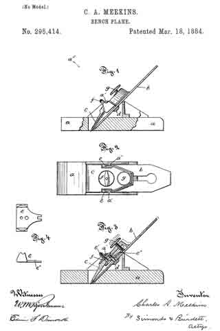
Figure 1 is a side view, with a portion of the sides of the stock represented as broken away. Fig. 2 is a view looking diagonally down upon the top from the point a5 over Fig. 1. Fig. 3 is a view of the plane in central vertical lengthwise section. Fig. 4. shows a detail top view of the rocking clamp-iron, and also a detail side view of the same.
The letter a denotes the stock or body of the plane, which may he partly of wood and partly of metal, or substantially wholly of wood or wholly of metal. In the drawings I show it with the bottom part composed of wood and the upper part of iron.
The letter b denotes the chisel or plane-iron, of the ordinary kind. The letter c denotes the cap-iron, which is novel in its construction; but it is secured to the plane-iron b, in substantially the ordinary way, by the connecting-screw d.
The letter e denotes what I call the “rocking clamp-iron,” because it has a rocking motion for effecting the adjustment of the plane-iron and cap-iron on the studs or pivots a’ a’; and it also serves in a novel manner the function of a clamp-iron-that is, it is the important factor in attaching the plane-iron and the cap-iron to the stock of the plane. This rocking clamp-iron runs under the cap-iron. The pin e’, jointed somewhat loosely at the bottom to the rocking clamp-iron, projects upward through the cap-iron, and upon the upper end bears the nut f, by means of which the plane-iron and cap-iron are clamped to the stock — that is, by running the nut down, the journal ends of the rocking clamp-iron press against the studs a’ a’, and the plane-iron is forced firmly down upon its seat. This rocking clamp-iron has an extended part or lever end, e”, the end of which is bifurcated, and takes hold of an annular groove in the adjusting-screw g, which is hung in the cap-iron.
By manipulating this adjusting-screw the edge of the plane-iron may be nicely adjusted. The mode or manner in which this is effected is not, perhaps, plain at a first glance; but the explanation is that by manipulating this adjusting-sorew the clamp-iron is rocked on pivots a’, and carries the plane and cap irons with it in its up and down but not its rocking movements.
I claim as my improvement —
1. In combination, the plane-body bearing the pivots, the plane-iron, the cap-iron attached to the plane-iron, the longitudinally-rocking clamp-iron, adjustably connected to the cap-iron and bearing between its points of connection upon the pivots on the plane-body, all substantially as described.
2. The oornbination of the longitudinally-rocking clamp-iron e, loosely attached to cap-iron e by pin e’ and nut f, adjusting-screw g, plane-iron b, and plane-body a, with pivot-bearings for the clamp-iron, all substantially as described.
CHARLES A. MEEKINS.
Witnesses:
SARA J. SIMONDS,
WM. E. SIMONDS.