
No. 556,608 – Oiling Attachment (Theodore Martin Anderson) (1896)
UNITED STATES PATENT OFFICE.
_________________
THEODORE MARTIN ANDERSON, OF NEW WHATCOM, WASHINGTON.
OILING ATTACHMENT.
_________________
SPECIFICATION forming part of Letters Patent No. 556,608, dated March 17, 1896.
Application filed March 8, 1895. Serial No. 541,035. (No model.)
_________________
To all whom it may concern:
Be it known that I, THEODORE MARTIN ANDERSON, of New Whatcom, in the county of Whatcom and State of Washington, have invented a new and Improved Oiling Attachment, of which the following is a full, clear, and exact description.
This invention relates to certain improvements in oiling or lubricating attachments, and has for its object to provide an attachment of this character especially designed for application to carpenters’ planes and the like to reduce the friction between the plane and the wood being dressed.
The invention will be hereinafter fully set forth and its novel features carefully defined in the claim.
Reference is to be had to the accompanying drawings, forming a part of this specification, in which similar figures of reference indicate corresponding parts in all the views.
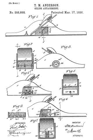
Figure 1 is a vertical longitudinal section taken through a plane of ordinary construction provided with my improvements. Fig. 2 is a transverse section taken through the oil-chamber in the plane indicated by the line 2 2 in Fig. 1. Fig. 3 is a side elevation showing the device for regulating the attachment. Fig. 4 is a view similar to Fig. 1, showing another form of my invention. Fig. 5 is a transverse section in the plane indicated by the line 5 5 in Fig. 4. Fig. 6 is a view similar to Fig. 4, illustrating still another modified form of the device. Fig. 7 is a transverse section in the plane indicated by the line 7 7 in Fig. 6, and Fig. 3 is a transverse section showing another modification which will be hereinafter described.
Referring primarily to Figs. 1, 2 and 3, 1 represents a plane of any preferred construction having a bit 2 and provided with parallel upwardly-extending side pieces or flanges and having at its rear part, behind said bit, an oil-chamber 3, having an outlet 4. extending across the under side of the plane-stock. As clearly seen in Figs. 1 and 2, the receptacle or chamber 3 for the oil is provided with a cover 7 arranged to slide in grooves 6 6 formed in the opposite side pieces of the plane.
The chamber or receptacle 3 will be filled with any suitable lubricating material — as for example, cotton waste or wool saturated with oil — and a wick 5 of any suitable kind is arranged in the said chamber, adapted to extend with its lower end through the outlet 4 to the under side of the stock. In order to adjust this wick 5, I employ disks 3 having spurs, said disks being mounted on a shaft 9 extending through the chamber 3 and provided at one end with a thumb-piece 10 arranged in a recess 10a in the outer face of the plane, as clearly seen in Figs. 2 and 3. By this construction it will be seen that when it is desired to use the attachment the thumb-piece 10 may be turned to move the wick down into contact with the surface of the wood to be dressed, and the oil will flow through the said wick and become evenly distributed over the lower face of the plane so as to reduce the friction.
When it is not desired to use the attachment, the thumb-piece 10 may be turned in a reverse direction so as to raise the wick 5 above the under side of the plane, as shown in Fig. 1.
In the construction seen in Figs. 4 and 5 I employ in lieu of the disks 8 and shaft 9 an eccentric 15 mounted on a shaft 12 and arranged to work in a slot formed in a block 16, having a serrated edge adapted to engage and hold the wick 5. The shaft 12 is screw-threaded to receive a nut 14 to hold the block 16 in place, and is provided at its outer end with a thumb-piece 13. Thus it will be seen that as the thumb-piece 13 is turned the block 16 will be moved up and down in the oil-chamber 3, carrying with it the wick 5.
In the construction seen in Figs. 6 and 7 the chamber 3 is provided with a slot 11 in its rear wall, and in said chamber is pivoted at 13 a lever 17, the rear end of which projects through the slot 11. The forward end of the lever 17 is bifurcated, and in its bifurcations is journaled a roller 19 having a wearing-surface covered with cloth or the like, and the periphery of said roller 19 extends through an opening in the bottom of the oil-chamber 3 into contact with the surface of the wood to be dressed. Behind the chamber 3 is located a spring 20, the arms of which are bent up and adapted to hold the projecting rear end of the lever 17, whereby said lever, when depressed to stop the flow of oil, will be held in its depressed position. In this form of the attachment the receptacle 3 is provided with a hinged cover 7x.
It is not essential that the wick employed in the construction shown in Figs. 1 and 4 shall extend entirely across the under side of the plane-stock. In some cases the chamber 3 may be provided with a series of outlets 4x as indicated in Fig. 8, and each of these outlets may be provided with a separate wick 5x, as will be readily understood. If desired, the wick may be in front of the bit instead ef behind the same, as shown.
From the above description of my invention it will be seen that the same is capable of considerable modification, and for this reason I do not wish to limit myself to the precise construction herein shown.
Having thus described my invention, I claim as new and desire to secure by Letters Patent —
A plane having a base portion formed with parallel and perpendicular sides having a block arranged between them and arising from the base portion, and a bit mounted between said sides and supported by the block, the block having an oil-chamber therein, substantially as described.
THEODORE MARTIN ANDERSON.
Witnesses:
H. H. ELLS,
G. H. BACON.