No. 680,056 – Plane (Edward S. Marks) (1901)

[paiddownloads id=”556″]680056


UNITED STATES PATENT OFFICE.

_________________

EDWARD S. MARKS, OF AUBURN, NEW YORK,
ASSIGNOR TO OHIO TOOL COMPANY, OF NEW YORK.

PLANE.

_________________

SPECIFICATION forming part of Letters Patent No. 680,056, dated August 6, 1901.
Application filed December 10, 1900. Serial No. 39,447. (No model.)

_________________

To all whom it may concern:

Be it known that I, EDWARD S. MARKS, a citizen of the United States, and a resident of the city of Auburn, in the State of New York, have invented certain new and useful Improvements in Planes, of which the following is a specification.

This invention relates to the devices by which the chisel is adjusted in relation to the plane-stock; and it consists in certain new constructions and arrangements of the parts by which this adjustment is effected.

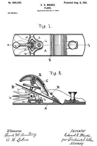
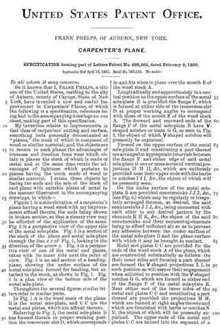
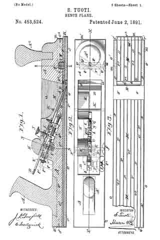
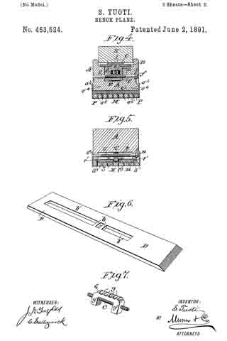
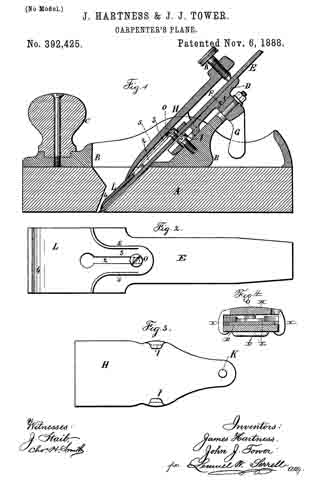
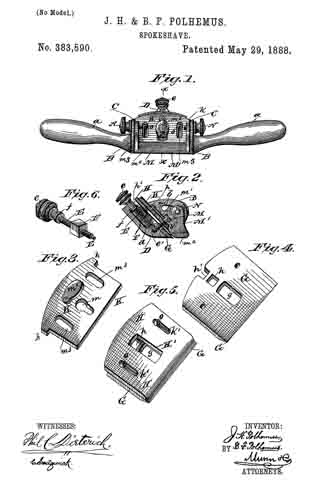
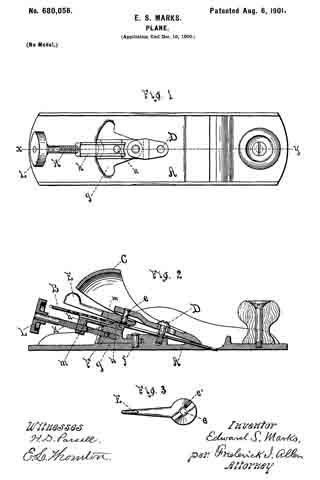
In the drawings, Figure 1 is a plan of a plane-stock provided with my improvements. Fig. 2 is a vertical section upon the line x y of Fig. 1, and Fig. 3 shows the lever separately.

Similar reference-letters indicate like parts in the several views.

In the drawings, A is the plane-stock. B is the chisel, which is secured by means of the cap C, which is held by the screw D and is locked by means of the lever E, pivoted at e and carrying a cam e’.

The foregoing parts are of usual construction.

Upon the plane-stock a carriage F is pivoted at f, which oscillates in the horizontal plane across the bed g. The carriage F is furnished with a slide h, seated thereon, and actuated by a screw K, which extends to the rear of the carriage F and is turned by its head L. A projection n upon the slide h, engages a corresponding depression or aperture m, in the chisel and holds the latter in position.

In operation the lengthwise adjustment of the chisel is performed by rotating the screw K, and by moving the carriage F upon its pivot f crosswise the lateral adjustment of the chisel is effected.

Wliat I claim as new, and desire to secure by Letters Patent, is —

In a plane and in combination; a plane-stock; a chisel mounted therein; means for clamping said chisel in said stock; a carriage pivotally mounted on said plane-stock so as to permit a lateral adjustment of said carriage and the parts supported thereby; a slide mounted on said pivoted carriage, and engaging said chisel ; and means carried by said carriage to adjust said slide and chisel longitudinally.

Signed at Auburn, New York, this 6th day of December, A. D. 1900.

EDWARD S. MARKS.

Witnesses:
H. D. PARSELL,
FREDERICK I. ALLEN.

No. 680,055 – Plane (Edward S. Marks) (1901)

[paiddownloads id=”555″]680055


UNITED STATES PATENT OFFICE.

_________________

EDWARD S. MARKS, OF AUBURN, NEW YORK,
ASSIGNOR TO OHIO TOOL COMPANY, OF NEW YORK.

PLANE.

_________________

SPECIFICATION forming part of Letters Patent No. 680,055, dated August 6, 1901.
Application filed December 4, 1900. Serial No. 38,705. (No model.)

_________________

To all whom it may concern:

Be it known that I, EDWARD S. MARKS, a citizen of the United States, and a resident of the city of Auburn, in the county of Cayuga and State of New York, have invented certain new and useful Improvements in Planes, of which the following is a specification.

This invention consists in certain new devices used to regulate the position of the chisel in relation to the plane-stock; and its object. is to furnish means for readily adjusting the chisel both longitudinally and laterally.

In the drawings, Figure 1 is a plan of a plane provided with my improvements and with the chisel and retaining-cap removed; and Fig. 2 is a sectional view upon the line x y of Fig. 1, showing the chisel and cap in position.

Similar reference-letters indicate like parts in both views.

In the drawings, A is the plane-stock, B is the chisel, and C the cap-iron, which is secured under the cross-bar D by means of the screw E.

The chisel B is provided with a rack b, and a pinion-section d, pivoted at f and operated by a lever K, engages it. The dotted lines of Fig. 2 indicate different positions which this lever may occupy in the vertical plane. By this means the chisel is moved in the direction of its length as required.

The carriage g, which supports the pivot f, is pivotally secured at h, so that it may be moved laterally, and the dotted lines of Fig. 1 show dilierent positions which it may occupy in the horizontal plane, the upright ears g’, rising from the carriage g, straddling the rack b on the under side of the chisel B and lengaging the parts for lateral adjustment, as shown in Fig. 2, the segment m upon the plane-stock furnishing a support for it in its different positions.

By the above-described means the chisel B is readily adjusted either vertically or laterally, as desired.

What I claim as new, and desire to secure by Letters Patent, is —

1. In a plane and in combination, a plane-stock, a chisel, means for clamping said chisel in said plane-stock, a carriage having a vertical pivotal connection with said plane-stock, a lever carried by and having a horizontal pivotal connection with said carriage to shift said carriage laterally on its pivot, means on said carriage to engage and shift said chisel laterally, and means on said pivoted carriage-lever to engage said chisel and shift it longitudinally.

2. In a plane and in combination, a plane-stock, a chisel, means for clamping said chisel in said plane-stock, a carriage having a vertical pivotal connection vvith said plane-stock, a segment formed on said stock to support said carriage, a lever carried by and having a horizontal pivotal connection with said carriage to shift said carriage laterally on its pivot, upright ears on said carriage to engage and shift said chisel laterally, and means on said pivoted carriage-lever to engage said chisel and shift it longitudinally.

Signed at Auburn, New York, this 1st day of December, A. D. 1900.

EDWARD S. MARKS.

Witnesses:
HENRY D. PARSELL,
FREDERICK I. ALLEN.

No. 661,010 – Plane (Maschil D. Converse) (1900)

[paiddownloads id=”549″]661010


UNITED STATES PATENT OFFICE.

_________________

MASCHIL D. CONVERSE, OF NEW YORK, N. Y.,
ASSIGNOR TO JOHN J. TOWER, OF SAME PLACE.

PLANE.

_________________

SPECIFICATION forming part of Letters Patent No. 661,010, dated October 30, 1900.
Application filed March 19, 1900. Serial No. 9,276. (No model.)

_________________

To all whom it may concern:

Be it known that I, MASCHIL D. CONVERSE, a citizen of the United States, residing in the city of New York, borough of Manhattan, county of New York, and State of New York, have invented certain new and useful Improvements in Planes, of which the following is a specification.

My invention relates to planes, and more particularly to adjustment mechanisms for the bits or irons thereof.

In planes constructed with clamp-plates and cramp-screws for securing the bit, more especially in those in which the end of the cramp-screw engages the surface of the bit, of which Letters Patent No. 619,394 is an example, it has been found that the point or end of the cramp-screw so indents and mars the surface of the bit that when it is desired to loosen the latter for adjustment the marred surface frequently interferes by either requiring the said cramp-screw to be so much loosened (to free the point or end of the indentations) that efforts to adjust the bit in one direction (either longitudinally or laterally) will cause the other adjustment to be lost or when retightening the cramp-screw its end will slip back again into the indentation or marrings on the bit’s surface, so that the desired adjustment is not with facility and certainty attained.

The objects of my present invention are not only to overcome these difficulties, but to provide a lateral adjustment mechanism which shall be adapted for use also in convertible planes of the type shown in Letters Patent No. 620,226 or analogous ones in which clamp-plates and cramp-screws essentially of the same character as hereinbefore referred to are employed, but in which the end of the cramp-screw instead of engaging the surface of the bit engages a slide or a socket in a slide, and the further object is to provide an inexpensive, simple, and efficient lateral adjustment device that may be expeditiously operated.

To these ends my invention consists in the several particulars of construction, arrangement, and combination of parts severally and more particularly hereinafter pointed out and claimed.

In the drawings, Figure 1 is a side elevation, partly sectional longitudinally, showing my invention as applied in planes of the herein-above first-mentioned type. Fig. 2 is a nether side view of the plane bit or iron, clamp-plate, and my invention removed from the stock, further showing the application and construction of certain parts thereof. Fig. 3 is a side elevation, partly sectional longitudinally, of the hereinabove second-mentioned type, showing the application of my invention to the same. Fig. 4 is a side elevation, partly sectional longitudinally, of one modiiied construction of my invention, sometimes desirable in applying it to this second-mentioned type of planes; and Fig. 5 is a side elevation, partly sectional longitudinally, showing a further-modified application of my invention to this type of planes. These several figures will now be more fully described in detail.

Like letters and the same primed indicate corresponding parts throughout the respective figures.

A in Fig. 1 is the stock of a plane of the hereinabove first-mentioned type, having the usual handle B and knob C and provided with a post D, centrally upon which is mounted obliquely a longitudinally-movable plate E, forming the bed for the bit G, above which is another plate H, also longitudinally movable, which latter I construct with an arch a (said arch being one feature of my present invention) and provide with a cramp-screw J, which passes from the upper side through the outer portion at substantially right angles to its longitudinal plane.

I is a worm-screw (provided with a lever l and pivoted to the post D) to engage a rack K on the under side of the nether clamp-plate or bed E, making a known device for longitudinal adjustment of the bit.

L in Figs. 1 and 2 is a longitudinal slot in the bit having equal dimensions transversely throughout its extent. M in the same figures is a concave-convex thumb-wheel, preferably gnarled or milled on its extreme upturned periphery, having a hole through its axis for reception of the reduced portion or end of the cramp-screw (which latter is made with a shoulder N, as in Figs. 1, 3, and 5) or for the reception of the journal e, as in Fig. 4. This thumb-wheel is provided with an eccentric O, (which I prefer to be integral,) extending from the convex side to enter the slot L and engage the lateral parallel walls thereof. The diameter of this eccentric should be so nearly equal the transverse measurement of the slot L as barely to slide freely therein. The surface immediately surrounding the eccentric radially on the convex side of the thumb-wheel at P, I level or flatten in order that the same may have a considerable area for engagement with the upper side of the plane-bit G by overhanging the lateral margins of the slot L. The arch ct of the clamp-plate H is for the accommodation of the upturned periphery of the thumb-wheel, which latter is so made in order that it may be accessible to the thumb and finger of the operator.

At Q it will be seen that the hole in the axis of the thumb-wheel on the convex side is countersunk and that a portion of the reduced pivot or pivot end is upset at b, so as to prevent the said thumb-wheel from becoming separated from the clamp-plate H when the bit is being removed.

Those skilled in the art will now see that in the operation of my invention the upturned periphery of the thumb-wheel gives convenient access (as before stated) for its manipulation by the thumb and finger of the operator, a construction for the thumb-wheel made possible when placed below the clamp-plate H by the arch a of the latter, that turning the thumb-wheel to either the right or left will accomplish lateral adjustment of the bit, and that the overhanging radially-extended flattened surface of the convex side of the thumb-wheel at P offers an area of sufficient extent to prevent indentation or marring of the surface of the bit, which it engages when the cramp-screw J is tightened, and because the point or end of the cramp-screw is not employed to engage the bit, but its pressure is communicated to the latter by means of the shoulder N, through the thumb-wheel, the under or convex side of which latter bears upon and binds the bit, except in the modification shown by Fig. 4, where the journal or pivot of the thumb-wheel and eccentric is independent of the cramp-screw and is not axially coincident therewith, which cramp-screw, however, in such case does not engage the surface of the bit, but engages a slide or a socket in a slide, as before mentioned, while in the modification shown by Fig. 5 a stud S is fixed in the clamp-plate to engage the socket in the slide (but without pressure on the bottom of the socket) instead of the cramp-screw. The advantages of the device of an arched clamp-plate H, with a thumb-wheel of the form described, will also be readily seen by such both on account of great economy of manufacture (since they severally may be cast in integral parts) and greater efficiency and convenience in operation.

I do not herein claim, broadly, the application of a lateral bit-adjustment mechanism to have its fulcrum coincident to the axis of the cramp-screw, such having been claimed and allowed to me in Letters Patent No. 619,394, dated February 14, 1899, nor do I wish to limit myself in my present invention to a combination with the cramp-screw as a pivotal axis therefor, since manifestly the improved form and construction of the leading features of my present invention adapt it to be employed on an independent pivot similarly to that shown in Fig. 4.

Having described my invention, what I do claim as new, and desire to secure by Letters Patent, is —

1. In a plane a lateral bit-adjustment mechanism comprising an arched clamp-plate carrying a pivot and cramp-screw, a concavo-convex thumb-wheel revolubly mounted on said pivot, provided with an eccentric on its convex side and a radially-flattened surface thereon adjacent to said eccentric, in combination with a longitudinally-slotted bit.

2. In a plane a lateral bit-adjustment mechanism comprising an arched clamp-plate carrying a shouldered pivot and cramp-screw, a concavo-convex thumb-wheel revolubly mounted on said pivot, provided with an eccentric on its convex side and a radially-flattened surface thereon adjacent to said eccentric, in combination with a longitudinally-slotted bit.

3. In a plane a lateral bit-adjustment mechanism comprising an arched clamp-plate carrying a pivot and cramp-screw, a concave-convex thumb-wheel revolubly mounted on said pivot, provided with an eccentric on its convex side and a radially-flattened surface thereon adjacent to said eccentric and means for preventing the said thumb-wheel from becoming accidentally detached from said clamp-plate, in combination with a longitudinally-slotted bit.

In testimony whereof I afiix my signature in presence of two witnesses.

MASCHIL D. CONVERSE.

Witnesses:
H. S. WELCH,
FRANK A. JONES.

No. 643,313 – Hand-Planer (Francis Witzmann) (1900)

[paiddownloads id=”543″]643313


UNITED STATES PATENT OFFICE.

_________________

FRANCIS WITZMANN, OF NEW YORK, N. Y., ASSIGNOR OF ONE-HALF
TO ALEXANDER MONAGHAN, OF NEW ORLEANS, LOUISIANA.

HAND-PLANER.

_________________

SPECIFICATION forming part of Letters Patent No. 643,313, dated February 13, 1900.
Application filed March 25, 1899. Serial No. 710,475. (No model.)

_________________

To all whom it may concern:

Be it known that I, FRANCIS WITZMANN, a citizen of the United States, residing in New York city, borough of Manhattan, State of New York, have invented certain new and useful Improvements in Hand-Planers, of which the following is a specification.

The object of my invention is to provide a planer that shall be capable of planing the heads of barrels, kegs, tubs, and the like, while assuring that the hands of the operator need not come in contact with the chime, and which shall also be capable of planing other surfaces.

The invention consists in the novel details of improvement and the combinations of parts, that will be more fully hereinafter set forth and then pointed out in the claims.

Reference is to be had to the accompanying drawings, forming part hereof, wherein —

Figure 1 is a front view, partly in section, of a hand-planer embodying my invention. Fig. 2 is a vertical cross-section thereof. Fig. 3 is an inverted plan view of the planer. Fig. 4 is a detail and transverse sectional view of a clamp or wedge, and Fig. 5 is a detail sectional view of the handle.

In the accompanying drawings, in which similar letters of reference indicate corresponding parts in the several views, A indicates a frame of suitable construction, and which is shown provided with a bottom plate a, having a slot or opening a’, opposed side walls a2, and upwardly and outwardly inclined back wall J, upon which a blade B is adapted to rest so thatits lower cutting edge will project into or through the opening a’.
(See Fig. 2.)

C is a clamp or wedge that is adapted to bear upon the blade B to hold the latter in the operative position. Means are provided for retaining the clamp C in such position that its lower beveled edge will aline with and lie near the cutting edge of the blade B, and for this purpose I have shown the clamp C as provided with projections or tongues P, that are adapted to pass into grooves D in the walls a2, which grooves are shown parallel with the walls J and the blade B and above the latter, and the lower ends m, of these grooves form abutrnents, against which the ends l of projections or tongues P rest to regulate the distance that the clamp C can be pushed into the frame. The clamp is held in place so as to create a pressure upon the blade B by means of screws F, which mesh in threaded bores c in lugs d, cast on the inner faces of walls a2 and extending upwardly above the clamp C, the lower ends of these bores c opening above said clamp to enable the ends of the screws F to bear upon the clamp. (See Fig. 2.) The lower parts of lugs d are shown reduced to allow greater freedom for the passage of chips. In line with the bores c the clamp C is provided on its upper surface with countersunk recesses k, into which the tapered ends of the screws F fit.

From the foregoing it will be understood that the clamp C is retained in the lower working position by the projections or tongues P, engaging the abutments m, and that the screws F by entering the recesses k keep the clamp from slipping out of place. By forcing the screws F upon the clamp the latter will hold the blade B rigidly in the cutting position, and by slacking back the screws the pressure of the clamp upon the blade will be reduced and the blade can be readily adjusted more or less into the cutting position to make the desired depth of cut. It will also be seen that when the blade is withdrawn from the frame the clamp will still remain in the working position. As shown, the winged ends of screws F project above the upper edges of the sides a2 of the frame A in position to be readily operated, and the lower edge of the clamp can be seen through the top opening of the frame, whereby as the clamp remains in position it acts as a sight-guide in adjusting the cutting edge of the blade B to a true position transversely of the frame.

The side walls a2 of the frame A are carried high up from the lower wall a, and there is an open space between said walls, as shown in Fig. 1, and to these walls handles G are attached, which extend outwardly in opposite directions. The handles G are thus elevated sufliciently high so that the hands of the operator will not come in contact with the chime of a barrel, keg, or tub when the head of the same is being planed, and by this means practically the entire surface of the barrel-head (except for a slight distance inwardly from the chime) can be planed uniformly and smoothly or a brand or label readily planed or scraped from the same and a perfect command of the tool is afforded. Any suitable means may be provided for attaching the handles to the frame. I have shown a screw or threaded rod H, which meshes in threaded apertures I in the upper portion of the side walls of the frame, and the handles G have threaded apertures that mesh with the screws H, and by preference ferrules N surround the inner ends of the handles and abut, respectively, against shoulders on the handles and against the outer surface of the side walls a2.

The lower edges of the outer sides of the frame A are shown curved, so as to conform somewhat to the curve of the chime or flange of the barrel, keg, or the like whose head or cover is to be planed. (See Fig. 3.)

I do not limit my invention to the details of construction shown and described, as they may be varied without departing from the spirit thereof.

Having now described my invention, what I claim is —

1. In a hand-planer, a frame having an opening in its lower face for a blade and grooves in its side walls parallel to the plane of the blade-seat, combined with a clamp having projecting portions to engage said grooves, the ends of the grooves forming abutments to limit the downward movement of the clamp-plate, and screws carried in threaded apertures in the frame adapted to bear upon said clamp to press the same upon the blade, substantially as described.

2. In a hand-planer, a frame having an opening in its lower face for a blade and grooves in its side walls parallel to the plane of the blade-seat, combined with a clamp having projecting portions to engage said grooves, and provided with recesses on its upper face, the ends of the grooves forming abutments to limit the downward movement of the clamp-plate, and screws carried in threaded apertures in the frame adapted to enter the recesses in the clamp to retain the same in position in the frame and to press the clamp upon a blade, substantially as described.

3. In a hand-planer, a frame having a bottom wall and opposed side walls rising from the same, and means for retaining a blade in said frame, combined with a pair of handles each attached to and projecting laterally from the outer surface of one of said side walls at the top portion of said walls, substantially as described.

In testimony that I claim the foregoing as my own I have hereto affixed my signature in the presence of two witnesses.

FRANCIS WITZMANN.

Witnesses:
GEORGE HILL,
WM. H. HEINECKE.

No. 619,394 – Bench-Plane (Maschil D. Converse) (1899)

[paiddownloads id=”538″]619394


UNITED STATES PATENT OFFICE.

_________________

MASCHIL D. CONVERSE, OF NEW YORK, N. Y.,
ASSIGNOR TO JOHN J. TOWER, OF SAME PLACE.

BENCH-PLANE.

_________________

SPECIFICATION forming part of Letters Patent No. 619,394, dated February 14, 1899.
Application filed June 20, 1898. Serial No. 683,931. (No model.)

_________________

To all whom it may concern:

Be it known that I, MASCHIL D. CONVERSE, a citizen of the United States, residing in the city, county, and State of New York, have invented certain new and useful Improvements in Bench-Planes, of which the following is a specification.

My present invention relates more especially to that type of bench-planes commonly made with iron stocks, and particularly to sidewise-adjustment mechanisms for the same.

Planes have been provided with mechanisms for lateral adjustment that in many cases are so constructed, disposed, and applied as to involve piercing of the bits with holes or slots or cutting of grooves longitudinally in one or the other of the flat sides thereof, requiring in consequence that the bits be made thicker and heavier than is desirable to compensate for the lack of stiffness that would result from such form in the bit and otherwise, and in other cases the construction and manner of disposing and applying such mechanisms are such that they encroach upon the radial hand-space about the handle of the plane, more especially on the front side thereof, seriously interfering with and sometimes to the injury of the hand of the operator, and by such near proximity, especially of the free ends of the operating-levers, the bits are constantly liable to be and are thereby frequently accidentally disturbed and put out of lateral adjustment.

The objects of my invention are to overcome these defects, to simplify construction, reduce the cost of manufacture, and improve the efficiency of such tools.

My invention consists in placing the fulcrum-point of a mechanism for lateral adjustment of the plane-bit at the bearing end of a cramp-screw in the outer end of the upper bit-clamp plate or in axial coincidence therewith and in so constructing and disposing all parts of said mechanism that the objects above stated will be attained, all of which will hereinafter be fully described and claimed.

In the drawings, Figure 1 is a side elevation of a bench-plane of the class referred to, showing the construction, application, and disposition of the members in part of my invention. Fig. 2 is a plan view of parts of Fig. 1, showing further the construction, application, and operation of my invention. These figures will presently be more fully described in detail.

Like letters indicate corresponding parts in each figure.

A is a stock, block, or body of a bench-plane of common pattern, having the usual handle B, knob C, and a post D, centrally upon which is mounted a longitudinally-movable inclined plate E, forming a bed for the bit G, above which is another plate H, also longitudinally movable, with a cramp-screw J passing through its outer extremity from the top side, which, together with the said named plates E and H, comprises a screw-cramped clamp for securing the bit G after its adjustment laterally and longitudinally is effected.

I is a worm-screw (provided with a lever s) fastened pivotally to the post D to engage a rack K on the nether bit-clamp plate or bed E, making a known device for adjustment of the bit longitudinally.

a is a metal strap or casting, preferably arranged on the upper side, with ends b b turned right angularly to embrace the outer parallel edges c c of the bit G.

d is a lever operatively pivoted to the center of the strap at e, said lever being fulcrumed on the bearing end of the cramp-screw J in the outer end of the plate H and preferably arranged in a plane above the lateral plane of the bit G. The free end f of this lever d, which is also preferably disposed along the upper side of the bit, is suitably elongated and formed up to insure ease and accuracy of movement in manipulation.

The clamp-plates E and H are so attached to each other and to the post D, which is integral with the stock A, that while each has longitudinal freedom they have substantially no edgewise play. Therefore the fulcrum of the lever d, being on the bearing end of the cramp-screw J at the outer end of the upper bit-clamp plate H, is substantially fixed against lateral movement relatively the plane-stock A. The bit G, on the contrary, is fitted so as to have considerable edgewise freedom at its outer end, while the cutting end is confined against lateral movement, the purposes of which are apparent.

The mechanical operation will be readily understood without further explanation; but it should be specially noted that by a mechanism for lateral adjustment having the disposition of parts with the location and means of fulcrumage herein shown and described the necessity and cost of grooving or piercing of the bits is avoided, so that the same may with advantage be made lighter in consequence, and, moreover, encroachment upon the radial hand-space about the plane-handle is obviated and liability to injury to or accidental disturbance of lateral adjustment of the bit by contact of the operator’s hand wholly overcome. I fulcrum the lever d upon the bearing end of the cramp-screw J for convenience and economy; but it may be fulcrumed by independent means axially coincident to the cramp-screw.

I do not claim a transverse strap or bar, broadly, in a device to engage a plane-bit for its adjustment, such having been used and described in Letters Patent No. 64,790 as early as May 14, 1867; but,

Having described my invention, what I do claim as new, and desire to secure by Letters Patent, is —

1. In a bench-plane, a lever-actuated mechanism adapted to engage the outer edges for lateral adjustment of the bit, having its lever fulcrumed to the bearing end of a cramp-screw in the outer end of the upper bit-clamp plate, the whole constructed and arranged substantially as and for the purposes shown and described.

2. A lever-actuated lateral-adjustment mechanism, having a fulcrum axially coincident to a cramp-screw in the outer end of the upper bit-clamp plate, arranged, relatively of the bit, substantially as and for the purposes shown and described.

3. A lateral-adjustment mechanism, having a fulcrum axially coincident to a cramp-screw in the outer end of an upper bit-clamp plate, arranged, relatively of the bit, substantially as and for the purposes shown and described.

MASCHIL D. CONVERSE.

Witnesses:
PAUL GORHAM,
DWIGHT W. DE MOTTE.

No. 609,681 – Router (Allen J. Kniffen) (1898)

[paiddownloads id=”537″]609681


UNITED STATES PATENT OFFICE.

_________________

ALLEN J. KNIFFEN, OF SCHENECTADY, NEW YORK.

ROUTER.

_________________

SPECIFICATION forming part of Letters Patent No. 609,681, dated August 23, 1898.
Application filed September 27, 1897. Serial No. 653,151. (No model.)

_________________

To all whom it may concern:

Be it known that I, ALLEN J. KNIFFEN, a citizen of the United States, residing at Schenectady, county of Schenectady, State of New York, have invented certain new and useful Improvements in Routers, of which the following is a specification.

This invention relates to that class of wood-working-tools known as “router-planes,” or, as more commonly called, “routers.”

The object of the invention is to provide a router in which the cutting-tool can be adjusted with precision and accuracy and secured in its adjusted position and also can be readily and quickly mounted in its support and removed therefrom.

The invention consists in a router constructed and arranged as hereinafter set forth and claimed.

Referring to the accompanying drawings, Figure 1 is a perspective view of a router constructed in accordance with this invention. Fig. 2 is a vertical section thereof through the middle,with the cutting-tool in full view; and Fig. 3 is a detail view, in horizontal section, showing the means for holding and securing the tool in place.

The router is provided with a base 1, as here shown of an oblong rectangular shape, having the two side recessed portions 2 and the central rectangular opening 3. Suitable handles 4 are mounted in the recessed portions 2. The back of the rectangular opening is formed with the raised portion 5, on which is mounted the cutting-tool. This consists of the cutting portion 6 on the lower end of the shank 7. The shank 7 is removably located in sleeves 8 9 8 of three bracket-arms 8′ 9′ 8′, the sleeves 8 8 being fixed to the upper and lower ends of a plate 10, mounted in the raised portion 5 in any suitable manner — as, for example, by means of a dovetailed joint — and secured thereto by a screw or other suitable means. The sleeve 9 is vertically movable between the sleeves 8 8, preferably in a suitable groove in plate 10, as here shown, especially in Fig. 3 of the drawings, the rear portion of sleeve 9 engaging a groove 10′, which serves as a guideway for the sleeve 9, as well as a seat therefor when it is locked in position. The sleeve 9 has also a slight lateral play. The sleeve 9 is provided on its rear with a threaded arm extending through a vertical slot 12 in plate 10 and the slot 13 in the raised portion 5, the slot 13 being in alinement with the slot 12. A wing 14 and washer 15, lying across the slot 13, are mounted on the arm 11 and serve to lock the sleeve 9 after the adjustment of the tool is effected and by drawing it laterally to clamp the tool- shank. The sleeve 9 is moved by means of an adjusting-screw 16, which has a threaded engagement with the bracket-arm 9′, the upper and lower ends of said adjusting-screw 16 being plain or unthreaded and extending through holes in the bracket-arm 8’. The screw 16 is held in place by a washer 17, located thereon beneath the upper bracket-arm 8’, and is operated by means of a milled head 16′ at its upper end. The shaft 7 of the cutting-tool extends through and is adapted to be slid vertically in the sleeves 8 9 8. In order that the shaft 7 may not drop out of the sleeve 8 9 8 when the wing-nut 14 is loosened, some means is necessary to hold it in frictional engagement therein, which also permits of its being adjusted in said sleeve before the sleeve 9 is adjusted. Any suitable means may be employed for holding the shaft in such frictional engagement.

As here shown, more particularly in Fig. 3, a spring 13 is employed, mounted in a recess 19 in the back of sleeve 9 and bracket-arm 9’, the outer or free end of spring 18 projecting into sleeve 9 and bearing against the shank 7. The rear of shank 7 is preferably formed with the flattened portion 20 to afford room and a better surface for the spring 18 to bear against shank 7.

In this class of devices it is necessary to readily and precisely adjust the cutting portion 6 to the depth required below the base 1, and this is effected as follows: The wing-nut 14 being loosened, the shank 7 is held in the sleeves 8 9 8 by frictional engagement of spring 20 and maybe pushed to approximately the desired position. The precise adjustment of the cutting-tool is then effected by turning the thumb-nut 16′, which moves the sleeve 9, carrying the cutting-tool, to the exact position desired. The tool is then rigidly held in such position by tightening the wing-nut 14, which draws the sleeve 9 against the groove 16’, firmly clamping the tool-shank and locking the parts in position. This binding action is very essential in tools of this kind, because if there is the slightest vibration in the tool it will not perform the work properly and will, as it is called, “chatter.” By having the parts mounted on the plate 10, as shown, they may be readily and quickly disconnected from the raised portion 5 for packing or repair by unfastening the plate 10 and sliding it out of position.

If preferred, in lieu of the plate 10 the bracket-arms 8′ may be mounted directly on the raised portion 5.

It will thus be seen that by means of a router constructed and arranged as herein set forth the cutting-tool can be easily placed in position or removed, will be held in this movable and removable position by frictional engagement, and can be quickly and precisely adjusted to the desired cutting position and locked in place.

Having described my invention, what I claim as new, and desire to secure by Letters Patent, is —

1. A router having fixed sleeves mounted on bracket-arms, an intermediate sleeve movable vertically and slightly laterally mounted on a movable bracket-arm, and an adjusting-screw for vertically adjusting the movable sleeve, in combination with a cutting-tool having a shank held in frictional engagement in said sleeve, and means connected with the movable sleeve for locking it to the main frame of the tool which also draws the movable sleeve laterally to clamp the tool-shank, as set forth.

2. A router having fixed bracket-arms carrying the sleeves, a vertically-movable bracket-arm carrying a sleeve which may be moved slightly laterally, and an adjusting-screw for vertically moving the movable sleeve, a groove in the main portion of the tool with which the movable sleeve engages, and a threaded arm, projecting from the movable sleeve, and having a nut for binding and locking the movable sleeve to the main frame of the tool and also drawing it laterally, in combination with a cutting-tool having its shank held in frictional engagement with said sleeve, as set forth.

3. A router having fixed brackets carrying sleeves, a vertical groove between said brackets, a movable bracket and sleeve engaging and movable vertically and slightly laterally in said groove, an adjusting-screw engaging said bracket, a threaded arm projecting from said movable sleeve through a slot in the bottom of said vertical groove, and a nut on said threaded arm for locking said movable sleeve in said groove, in combination with a cutting-tool, having its shank held in frictional sliding engagement in said sleeves, as set forth.

In witness whereof I have hereunto set my hand this 18th day of September, 1897.

ALLEN J. KNIFFEN.

Witnesses:
Mrs. A. J. KNIFFEN,
B. B. HULL.

No. 579,911 – Plane-Lubricating Apparatus (Johan Witzell) (1897)

[paiddownloads id=”528″]579911


UNITED STATES PATENT OFFICE.

_________________

JOHAN WITZELL, OF NEW YORK, N. Y.

PLANE-LUBRICATING APPARATUS.

_________________

SPECIFICATION forming part of Letters Patent No. 579,911, dated March 30, 1897.
Application filed June 13, 1896. Serial No. 595,434. (No model.)

_________________

To all whom it may concern:

Be it known that I, JOHAN WITZELL, a citizen of the United States,and a resident of New York city, in the county and State of New York, have invented certain new and useful Improvements in Plane-Lubricating Apparatus, of which the following is a specification.

My invention consists of improved means of periodically supplying lubricating-oil to the working face of the plane, as hereinafter described, reference being made to the accompanying drawings, in which —

Figure 1 is a side elevation of a wood-plane with a part in section, showing the application of my improved lubricating apparatus. Fig. 2 is a horizontal section of the plane on line 2 2, Fig. 1. Fig. 3 is a plan of the plane inverted.

Between the handle a and the seat b of the plane-bit c I provide an oil-reservoir d in any approved way with a suitable cover e, said cover having a plugged filling-aperture, as indicated at f, and I provide a lubricating-passage g through the bottom of the reservoir to the working face h of the plane with a valve i to open and close the same, said valve being on the lower extremity of a vertical stem j, extending up through the cover and thereat provided with a horizontal lever-arm j, normally extending from the stein located midway between the sides of the plane or thereabout to the right-hand side and inclined forward relatively to the lengthwise direction of the plane, about as represented in Fig. 2, so that it is convenient to engage the arm with one of the fingers of the hand holding the plane by the handle and working the plane and pull the arm backward to open the valve, which being thus pulled back is made to raise and open the valve by the curved inclined way k, which I have provided on the cover e for such effect.

Within the reservoir and between the cover e and the valve-top I have provided a coiled spring l, which presses downward on the valve and closes it when the arm j is released by the operator, the declivity of the way k being such that pressure of the spring will cause the arm to slide on it freely.

It will be seen that with my improved apparatus the supply of oil can be controlled at will and without interrupting the work. It will also be seen that the location of the lubricator between the seat of the plane-bit and the handle is more favorable for uniform lubrication of the working face throughout its entire length than when located in the knob forward of the bit. Besides the knob so utilized is not as reliable and serviceable for withstanding the hammer-shocks for jarring the bit slack as when solid and the shocks of the hammer are liable to force out spurts of oil.

I claim —

In a plane-lubricator, the combination of the reservoir located between the seat of the plane-bit and the rear handle of the stock, and having a passage communicating with the working face of the plane, the valve seated in said passage and having a stem extending upward through the cover of the reservoir, spring arranged between the cover and the head of the valve for closing said valve, the inclined way on the cover of the reservoir, and the arm of the valve-stem ranging over said inclined way in the relation to the handle for opening the valve by a finger of the hand gripping said handle substantially as described.

Signed at New York city, in the county and State of New York, this 11th day of May, A. D. 1896.

JOHAN WITZELL.

Witnesses :
CHARLES BRETTELL,
GEORGE BRETTELL.

No. 547,829 – Handle Attachment For Planes (John H. Williams) (1895)

[paiddownloads id=”518″]547829


UNITED STATES PATENT OFFICE.

_________________

JOHN H. WILLIAMS, OF TROY, NEW YORK.

HANDLE ATTACHMENT FOR PLANES.

_________________

SPECIFICATION forming part of Letters Patent No. 547,829, dated October 15, 1895.
Application filed July 31, 1893. Renewed May 25, 1895. Serial No. 550,719. (No model.)

_________________

To all whom it may concern:

Be it known that I, JOHN H. WILLIAMS, of the city of Troy, county of Rensselaer, and State of New York, have invented a new and useful Handle Attachment for Planes,of which the following is a specification.

My invention relates to a handle attachment for smoothing-planes to enable the latter to be operated when finishing off hard-wood or other floors without compelling the workman to sit or kneel on the floor. Where hard-wood fioors are finished off with smoothing-planes, the latter are operated by the workman when kneeling or sitting upon the floor, positions producing much discomfort; and the object and purpose of my invention are to have a handle that is attachable to or detachable from the plane, by which when connected with the latter it may be operated by persons standing on their feet.

Accompanying this specification, to form a part of it, there is a plate of drawings, containing two figures, illustrating my invention, with the same designation of parts by letter-reference used in both of them.

Of the illustrations, Figure 1 is a side elevation of a smoothing-plane with my handle attachment applied thereto. Fig. 2 is a perspective of the plane and handle attachment with the heel and sole of the plane facing the view.

The several parts of the plane and those containing my invention are designated by letter-reference, and the function of the parts is described as follows:

The letter S designates the stock; B, the bit or iron; W, the wedge holding the iron or bit in the bed b2. The letter T designates the top of the stock, and H its heel, all of which parts are the usual and well-known ones of a smoothing-plane.

The letter I designates the handle- body part, which is made with the handle-socket p2, the heel-piece h2, the bottom b at right angles to the heel-piece, and the upwardly-inclined top A, made with the projecting shoulder h3.

The letter C designates a clamp, which at its upper end tongues into the shoulder h3 and is thereat hinged by means of a hinging-bolt a. This clamp on its inner face is made with a shoulder m and above the latter has its face F parallel to the top A of the handle-body part.

The letter T2 designates a clamping-bolt made to pass downward through the clamp C and the handle-body part below the handle-socket p2, made in the latter, and the lower end of this bolt is threaded and provided with a nut N.

The letter D designates a handle, the lower end of which is adapted to be inserted in the socket p2 for operating the plane.

As thus made, the attachment of handle-body part and plane is made by placing the former with its bottom surface resting on the stock top and its heel-piece bearing against the heel of the stock, with the outer end of the plane iron or bit passing up between the upper part of the clamp and the inclined top A of the body part and with the plane-wedge W between the clamp and the inclined top of the body part below the shoulder h3 of the clamp, with the shoulder resting on said wedge, in which position the bolt T2 is passed down through the clamp and body part and the nut N screwed up onto the lower end of the bolt to bring the clamp and the plane parts, which it and the body part grasp, in close contact and engagement. As thus made, when grasped by the handle the plane may be operated to finish up a floor without the necessity of the workman who uses it getting down onto the floor to move it.

Having thus described my invention, what I claim, and desire to secure by Letters Patent, is —

In a handle attachment for a plane the combination with a body-part made with a heel piece, and constructed with a handle socket and handle; of a clamp hinged to the body-part and adapted to grasp the handle and wedge of the plane and a threaded bolt constructed to secure the parts as connected, substantially in the manner as and for the purposes set forth.

Signed at Troy, New York, this 17th day of September,1892, and in the presence of the two witnesses whose names are hereto written.

JOHN H. WILLIAMS.

Witnesses:
W. E. HAGAN,
CHARLES S. BRINTNALL.

No. 468,362 – Carpenter’s Plane (Frank Phelps) (1892)

[paiddownloads id=”483″]468362


UNITED STATES PATENT OFFICE.

_________________

FRANK PHELPS, OF AUBURN, NEW YORK.

CARPENTER’S PLANE.

_________________

SPECIFICATION forming part of Letters Patent No. 468,362, dated February 9, 1892.
Application filed April 16, 1891. Serial No. 389,185. (No model.)

_________________

To all whom it may concern:

Be it known that I, FRANK PHELPS, a citizen of the United States, residing in the city of Auburn, county of Cayuga, State of New York, have invented a new and useful Improvement in Carpenters’ Planes, of which the following is a specification, reference being had to the accompanying drawings on one sheet, making part of this specification.

My invention relates to improvements in that class of carpenters’ cutting and surface, smoothing tools generally denominated as “planes,” the stock of which is composed of wood or similar material; and the objects are to secure in such planes the advantages of trueness and freedom from wear which obtain in planes the stock of which is made of metal and at the same time retain the advantages of lightness which pertains to planes having the stock made of wood or similar material. I attain these objects by facing the ends and the sole of the stock of said plane with suitable plates of metal in the manner illustrated in the accompanying drawings, in which —

Figure 1 is a side elevation of a carpenteifs plane having a wood stock with my improvements aflixed thereto, the ends being shown in broken section, so that a clearer view may be afforded of the application of the same. Fig. 2 is a perspective view of the upper side of the metal sole-plate. Fig. 3 is a section of the stock of the plane and metal sole-plate through the line x x of Fig. 1, looking in the direction of the arrow z. Fig. 4 is a perspective view of one of the metal end plates, taken with its inner side next the point of view. Fig. 5 is an end section of a beading-plane, showing the under surface of the metal sole-plate formed for beading, but attached to the stock, as shown in Fig. 1. Fig. 6 is a plan view of the bottom side of the metal sole-plate.

Throughout the several figures similar letters refer to similar parts.

In Fig. 1 A is the wood stock of the plane. B is the metal sole-plate, and C C are the metal end plates, which are affixed thereto.

Referring to Fig. 2, the metal sole-plate B has formed therein in proper working position the transverse slot D, which corresponds to and fits when in place over the mouth E of the wood stock A.

Longitudinally and approximately in a central position on the upper surface of the metal sole-plate B is provided the flange F, which is formed at either side of the transverse slot D at proper working angles to correspond with those of the mouth E of the wood stock A. The forward and rearward ends of the flange F of the metal sole-plate B have V-shaped notches or seats G G, as seen in Fig.2, the object of which V-shaped notches will presently be explained.

Formed on the upper surface of the metal sole-plate B and constituting a part thereof are arranged at appropriate intervals between the flange F and either edge of said metal sole-plate B one or more series of vertical projections H H H, &c., which are uniformly provided near their upper ends with the barbs or notches I I I, &c., the object of which will be presently seen.

On the under surface of the metal sole-plate B are provided countersinks J J J, &c., 7 5 (see Fig. 6,) which may be regularly or irregularly arranged thereon, as desired, the said countersinks J J J, &c., being connected with each other in any desired pattern by the channels K K K, &c., the object of the said countersinks and their connecting-channels being to afford sufficient air so as to prevent any adhesion between the under surface of the metal sole~plate B and the plane surface with which it may be brought in contact.

Metal end plates C C are provided for the ends of the wood stook A of the plane, which are constructed substantially as follows: On their inner sides and forming a part thereof are formed the V-shaped projections L L in such position as will assure their engagement when adjusted to position with the V-shaped notches G G, which are formed in either end of the fiange F of the metal sole-plate B. Near either end of the inner sides of the metal end plates C C and constituting a part thereof are provided the projections M M, which are formed at right angles thereto and which are furnished with barbs or notches N N, the object of which will be presently explained. The upper ends of the metal end plates C C are turned into the segment of a circle, as shown, thus presenting a symmetrical outline and doing away with sharp and obtrusive corners.

The wood stock A of the plane has formed in a central longitudinal position of the sole thereof the groove a, the purpose of which will be presently explained.

Having thus described in detail the essential features of my invention, I will now describe their adjustment on the stock of the plane and their arrangement with relation to each other when such has been effected. The upper surface of the metal sole-plate B and the lower surface of the stock A of the plane are brought into immediate contact with each other by a compression brought to bear upon either or both powerful enough to force the several series of vertical projections H H H, &c., formed on the upper surface of the metal sole-plate B, which have been described, into the wood stock A of the plane, the fiber of which on retracting, after the said operation, engaging with and filling in beneath the barbs or notches I I I, &c., serves to assure the permanent fastening and securing together of the wood stock A and the metal sole-plate B. During this operation the flange F of the metal sole-plate B is entered in the groove a, Fig. 3, of the wood stock A, and thus serves to assure against any lateral displacement of the several parts described during and subsequent to the operation. The metal end plates C C are next brought into position on either end of the wood stock A of the plane by being forced by compression or by being driven thereon, as deemed most expedient. During this operation the V-shaped projections L L, which are formed on and project from their inner sides, engage with the V-shaped notches G G, which are formed in either end of the flange F of the metal sole-plate B and serve at the same time to bring the ends of the metal sole-plate B and the wood stock A of the plane into the closer contact and there lock them, as well as the lower ends of the said metal end pieces C C, into a joint with the ends of the metal sole-plate B, which project sufficiently beyond the ends of the wood stock A of the plane for that purpose. During this operation, also, the projections M M, which are provided on and project at right angles from the inner sides near either end of the said metal end plates C C, are forced into the wood of the wood stock A of the plane, the fiber of which, retracting, engages with and fills in behind the barbs or notches N N, formed thereon, thus substantially and permanently securing the metal end plates C C to the wood stock A of the plane and assisting, also, in the further permanent stability and securing of the ends of the metal sole-plate B, already described.

I am aware that metal plates for protecting and assuring the correctness of tools and instruments of precision, which are largely composed of wood and the said plates secured thereto in various ways, are and have for some time been in use; but I am not aware that such metal plates formed and arranged as has been described have been used in connection with carpenters’ planes or otherwise for the purpose and objects or in the manner set forth herein; therefore

What I claim as my invention, and desire to secure by Letters Patent of the United States, is —

I claim —

1. In a carpenter’s plane, the combination of a stock having a centrally-disposed longitudinal groove formed in its under surface with a metal sole-plate provided on its upper surface with a series of barbed vertical projections arranged near either side thereof, and a centrally-disposed longitudinal upwardly-projecting iiange, substantiallyin the manner and for the purpose herein described and specified.

2. In a carpenter’s plane, a stock having a centrally-disposed longitudinal groove formed in its under surface and a metal sole-plate provided on its upper surface with a series of barbed vertical projections arranged near either side thereof, a centrally-disposed longitudinal upwardly-projecting flange provided at either end with V-shaped notches, and a transverse slot D, in combination with the metal end plates provided on their inner sides with centrally-disposed V-shaped projections and near either end with barbed projections at right angles thereto, substantially in the manner and for the purpose herein specified and described.

3. In a carpenter’s plane, a stock having a centrally-disposed longitudinal groove formed in its under surface, a metal sole-plate provided on its upper surface with a series of barbed vertical projections arranged near either side thereof, a centrally-disposed longitudinal upwardly-projecting flange provided at either end with V-shaped notches, a transverse slot D, and the lower surface of said sole-plate provided with countersinks connected with each other by channels, and metal end plates provided on their inner sides with centrally-disposed V-shaped projections and near either end with barbed projections at right angles thereto, the whole combined and arranged in the manner and for the purpose herein described and specified.

In testimony whereof I have hereunto set my hand this 2d day of April, A. D. 1891.

FRANK PHELPS.

Witnesses:
JOHN J. TROWBRIDGE,
W. N. JENNINGS.

No. 466,494 – Beveling Attachment For Planes (Frank E. Hart) (1892)

[paiddownloads id=”481″]466494


UNITED STATES PATENT OFFICE.

_________________

FRANK E. HART, OF BROOKLYN, NEW YORK.

BEVELING ATTACHMENT FOR PLANES.

_________________

SPECIFICATION forming part of Letters Patent No. 466,494, dated January 5, 1892.
Application filed January 3, 1891. Serial No. 376,605. (No model.)

_________________

To all whom it may concern:

Be it known that I, FRANK E. HART, a citizen of the United States, residing in the city of Brooklyn, county of Kings, State of New York, have invented certain new and useful Improvements in Beveling Attachments for Planes, of which the following is such a full, clear, concise, and exact description as will enable others skilled in the art to which my invention appertains to make and use the same, reference being had to the accompanying drawings, forming part of this specification.

The object of my invention is to provide an attachment for a plane whereby the edge of a board, window-sash, door, or similar article may be reduced to the required angle and an accurate and predetermined bevel given without the aid of a square or other separate measure; and my invention consists in the improvements hereinafter more fully described, and pointed out in the claims.

In the drawings, Figure 1 is a view in elevation of an ordinary plane fitted with the improved attachment. Fig. 2 is an end view of the same, showing the plane in action upon a beveled surface. Fig. 3 is a plan view of end of plane with attachment connected, showing top of graduated segment. Fig. 4 is a side view of attachment unconnected, and Fig. 5 is a rear view of the same.

The plate A, having flanges a a’, maybe conveniently secured to the plane B by means of the binding-screw C, and pivoted to this plate are the adjustable guiding arms or bars D and E, extending downward from opposite sides. The arms D and E of course might, if desired, be secured directly to the body of the plane The arm D is preferably formed with a slotted graduated sector d, adapted to be secured by the binding-screw d’, whereby the said arm may be held at any desired angle to the lower surface of the plane, while the arm E is shown as provided with a slotted elbow e, which, moving upon and about the screw e’, permits the arm E to be brought parallel to the arm D and also to approach and withdraw from the same. The lower ends of the guiding-arms D and E are, moreover, preferably provided with flanges d2 e2, which are shown as slightly beveled or inclined, giving thus a greater guiding-surface, while at the same time allowing the necessary oscillation and freedom in the movement of the plane. Further, the flange d2 forms a convenient rest for the finger of the artisan.

It is readily seen that when the guiding-bars D and E are adjusted to any position other than the perpendicular the plane will be made to bear unevenly, cutting more on one side than the other, until A the surface to be smoothed or reduced becomes parallel to the bottom of the plane and its slant or bevel corresponds with the inclination of the guiding-arms.

Having thus fully described my invention, what I claim as new, and desire to secure by Letters Patent, is —

l. In combination with a plane, guiding-arms pivoted thereto and extending downward from opposite sides, said arms being adapted to be secured at an angle, whereby the plane is inclined and made to bear unevenly until the surface acted on is smoothed or reduced to the slant or bevel desired, substantially as set forth.

2. In combination with a plane, a plate adapted to be secured thereto and provided with adjustable guiding-arms extending downward from opposite sides, whereby the plane is inclined and made to bear at an angle, substantially as and for the purpose set forth.

3. In combination with a plane, a plate adapted to be secured thereto, and guiding-arms pivoted to said plate and extending downward from opposite sides, the said arms being provided at their lower ends with beveled fianges, substantially as and for the purpose set forth.

4. In combination with a plane, the flanged plate B and guiding-arms D and E, having graduated sector d and slotted elbow e and flanges d2 and e2, all arranged and secured substantially as described.

FRANK E. HART.

Witnesses:
PERCY GRIFFITH,
WM. J. WINBERG.

No. 458,676 – Hand-Plane (James H. Ferguson) (1891)

No. 458,676 – Hand-Plane (James H. Ferguson) (1891)

[paiddownloads id=”477″]458676


UNITED STATES PATENT OFFICE.

_________________

JAMES H. FERGUSON, OF BROOKLYN, NEW YORK.

HAND-PLANE.

_________________

SPECIFICATION forming part of Letters Patent No. 458,676, dated September 1, 1891.
Application filed April 16, 1889. Serial No. 307,485. (No model.)

_________________

To all whom it may concern:

Be it known that I, JAMES H. FERGUSON, of Brooklyn, in the county of Kings and State of New York, have invented a certain new and useful Improvement in Hand-Planes, of which the following is a specification.

My improvement is designed more particularly for planing the sides of electrotype or stereotype plates, but it may be employed for other purposes.

In the accompanying drawings, Figure 1 is a side elevation, partly in section, showing a plane embodying my improvement. Fig. 2 is a plan or top view of the same. Fig. 3 is an end view of the same. Fig. 4 is a sectional elevation illustrating a modification, certain of the parts being broken away to save space. Fig. 5 is a vertical section of the same, taken on the line x x, Fig. 4, certain of the parts shown in Fig. 4 being removed. Fig. 6 is a view in elevation, partly in section, illustrating how my improvement may be employed with another kind of plane.

Similar letters of reference designate corresponding parts in all the figures.

In the example of my improvement illustrated in Figs. 1, 2, and 3 the body of the plane is made in the form of a box and is formed of a single piece of metal — as, for instance, by casting. Near its forward end the face of the plane is provided with an elastic portion A, which normally occupies an elevated position, but which may be pressed downwardly at its inner end portion l, so as to regulate the depth of cut which will be made by the plane-iron E. In order to cause the requisite degree of elasticity, the portion A is separated throughout its length and upon its sides from the sides of the plane-body D by slits or slots b, which extend through the metal of the portion A and upwardly through the end A’ of the plane-body D. It will be seen that by pressing downwardly the inner end portion of the portion A its position may be deflected to any desired extent in order to increase the depth of cut which will be made by the plane-iron. In order to accomplish this deflecting of the portion A, I have shown a screw e, having bearings in a cross-piece d, secured in the sides of the plane-body. By manipulating this screw the deflecting or bending of the portion A may be regulated to any desired extent.

In the example of my improvement shown in Figs. 4 and 5 the operation is precisely like that just described; but there is some slight difference in the mode of constructing the slit or slot b. In this example the slot extends along the sides of the plane-body and downwardly at the inner end of the portion A. Of course the outer end of the portion A is not separate from the sides of the plane-body, except to the thickness of the sides of the body.

In Fig. 6 I have shown the application of the improvement to a so-called “jack-plane” having a body of cast metal. When used with the jack-plane, either one of the means for separating the portion A, so that it will be elastic, may be employed which I have described in the other examples of my improvement shown. I have, however, illustrated that as shown in Figs. 1, 2, and 3.

In all the examples of my improvement shown the portion A when occupying a normal position stands back slightly from the other part of the face of the plane, so that when in such a position the plane-iron will be capable of making its maximum cut.

It will be seen that by my improvement I provide a very inexpensive and ready means for varying the depth of cut which may be made by the plane-iron without going to the necessity of adjusting the plane-iron separately; or, in other words, the plane-iron once having been set it will not be necessary to alter it in order to obtain any desired adjustment for depth of cut.

What I claim as my invention, and desire to secure by Letters Patent, is —

The combination, with a plane-body made in one integral piece and having a portion of its face near one end elastic, but formed integral therewith, of an adjusting device operating upon said elastic portion to cause a deflection thereof, said elastic portion normally occupying a position whereby it is set in beyond the face, substantially as and for the purpose specified.

JAMES H. FERGUSON.

Witnesses:
FREDK. HAYNES,
JOHN BICKEL.

No. 453,524 – Bench-Plane (Saverio Tuoti) (1891)

[paiddownloads id=”474″]453524


UNITED STATES PATENT OFFICE.

_________________

SAVERIO TUOTI, OF NEW YORK, N. Y.

BENCH-PLANE.

_________________

SPECIFICATION forming part of Letters Patent No. 453,524, dated June 2, 1891.
Application filed August 7, 1888. Serial No. 282,165. (No model.)

_________________

To all whom it may concern:

Be it known that I, SAVERIO TUOTI, of the city, county, and State of New York, have invented a new and Improved Bench-Plane, of which the following is a full, clear, and exact description.

My invention relates to bench-planes for wood-workers’ use, and has for its object to provide a simple, easy-working, efficient, and durable plane of this character.

The invention consists in certain novel features of construction and combinations of parts of the plane, all as hereinafter described and claimed.

Reference is to be had to the accoinpanying drawings, forming a part of this specification, in which similar letters of reference indicate corresponding parts in all the figures.

Figure 1 is a vertical longitudinal section of my improved bench-plane, taken on the line x x in Fig. 2. Fig. 2 is a plan view of the plane partly broken away and in section. Fig. 3 is a bottom face view of the plane partly broken away. Fig. 4 is a vertical transverse section of the plane, taken on the line y y in Fig. 1. Fig. 5 is a cross-section taken on the line z z in Fig. 1. Fig. 6 is a top perspective view of the plane iron or cutter, and Fig. 7 is a detail perspective view of the nut and part of the screw by which the cutter is adjusted endwise.

The plane-stock A is made with the usual top recess a, which opens to a throat or passage a’, up through which escape the shavings made by the cutter B, which rests on or at the inclined bottom face or wall of the recess.

In the plane-stock and at the lower inclined wall of the recess a there is formed a groove or recess to accommodate a screw C, which is fitted at its forward end in a metal step-bearing c, set into the stock, and at its rear part is reduced in diameter at two places c’ c2, which form journals which are fitted, respectively, to a split box or bearing D and a block E. The two halves or parts of the bearing D are screwed or otherwise fixed to the plane-stock, and the block E is also a nut, into which is fitted a transversely-ranging screw F, which is journaled to or in the plane-stock and cannot move endwise, and has a head or finger-piece f which is accommodated in a recess made in the side of the plane-stock and does not project beyond the stock, and thus does not interfere with the free working of the plane.

The nut E is provided with an upper lug e, which fits laterally within the slot b’ of the plane iron or bit B, and the nut is laterally slotted at e’, where the main adjusting-screw C passes through it, and whereby as the screw F is turned the nut E may be caused to move laterally either way in the plane-stock, and the nut-lug e will shift the back end of the plane-iron laterally to adjust the cutting-edge of the iron properly with relation to the working-face of the plane either before or after the iron has been adjusted endwise by the main screw C, working in a nut G, fitted on it, and as presently explained. It will be noticed that the bearing and nut D E, by fitting the reduced parts of the screw C, prevent endwise motion of the screw.

The nut G is preferably formed with pendent end lugs g’ g’, into which the screw C is fitted, and at its upper face the nut is provided with a series of transverse notches g, into which one or more transverse bars b, which cross the plane-iron slot b’, are adapted to enter when the plane-iron is adjusted in the stock.

The wedge H is provided at its lower face with a plate I, which is fixed to the wedge at one end and at its other or free end is adapted to bear on a cross-bar b of the plane-iron or on the adjusting-nut or on both the cross-bar and nut, and onto which the plate I, which is preferably elastic, may be forced by a screw J, fitted into the wedge and preferably into a metal nut j, set into it. The forward end or part of the wedge enters beneath a cross bar or rod K, fixed in the stock across its recess a, and the bar forms a fulcrum on which the wedge will rock when the screw J is tightened to cause its extrerne front end h’ to clamp the plane-iron down hard to the plane-stock very near the cutting-edge of the iron, and thus firmly hold it to prevent chattering of it when the plane is in use and assuring smooth clean work. The effect in this respect would be the same were the plate I dispensed with, in which case the screw J would bear directly on the plane-iron or on its adjusting-nut; but the plate I is preferably used, as it guards the plane-iron or its nut from injury by the end of the screw and assures a better clamping action of the wedge than would be afforded without it.

The screw C is provided at its rear end with a bevel-pinion c3, which meshes with a like pinion l3 on a short shaft l2, journaled in a bearing l’ on the plane-stock and provided with a head or finger-piece l, by turning which the screw C will be turned to shift the nut G for adjusting the plane-iron endwise for a finer or coarser cut, and which may be done without loosening the wedge-clamping screw. When the plane iron or cutter wears so it cannot be set farther ahead by operating the screw, the cross-bar b of the iron may be set into another front notch g after the nut is run back on the screw, this adjustment allowing all the tempered forward part of the iron to be used.

The plane-stock has the usual back and front handles A’ A2, andis also provided with a working-face of peculiar construction, the front part of which face is made adjustable backward or forward to narrow or broaden the shaving-throat a’ of the plane-stock, and as will next be described.

The larger section or portion M of the plane-face and its smaller adjustable section or portion N are made on the same general principle, or with a metal frame having strips of hard wood inserted in longitudinal grooves thereof. The face-section M is made with a cast-metal frame O, which has a broad cross-bar o behind the shaving-throat a’ of the plane-stock and beveled at the upper face to give substantial support to the plane-iron and to prevent undue wear of that part of the plane-face just behind the cutting-edge of the iron or at the back of the shaving-throat of the plane-stock, which usually wears quickly when made wholly or partly of wood. From each side of the cross-bar o there projects a forward ex-
tension o’ of the metal frame O, which form forward side parts m m of the main face-section M. These parts o’ o’ give support to the front sliding section N of the plane-face, as presently described, and at their front ends and above the section N they are connected and braced by a fIange-piece or bar m’, which is screwed to the front end of the plane-stock and really forms the front cross-bar or part of a flange o2, which projects upward all around the frame O and above its solid top plate o3 far enough to receive screws o4, which pass through the flange to hold the frame O and its front extensions o’ o’, or, in other words, the entire main plane-face section M m m, securely to the plane-stock.

Behind the metal cross-bar o and within the margin of the frame O said frame is provided with a series of longitudinally-ranging thin metal ribs or plates o5, which are cast on the back plate o3 of the frame and are set apart to provide spaces or form grooves between them, and into which are tightly fitted a series of hard-wood strips P, and the forward extensions o’ o’ of the frame O are also made hollow to accommodate like strips P, as most clearly shown in Figs. 3, 4, and 5 of the drawings.

The plane-face section N consists of a metal frame R, the inner face-plate r of which is provided with side tongues r’ r’, which enter grooves made in the opposite front side extensions m m of the main plane-face section M. On the plate r and between end lips or flanges r2 r2 of the frame R there is cast a series of lips or plates r3, set apart to provide between them a series of grooves or spaces, into which are tightly fitted a series of hard-wood strips S, like those P of the other face-section M.

In the forward end of the plane-stock and above its face-section N is provided a transverse slot or groove t, which accommodates a nut-block T, fitted to threads of a screw U, which is journaled in the plane-stock and traverses the recess t, and is provided at one end with a finger-piece or head u, which works in a recess at the side of the stock, so as to be out of the way in working the plane. The ends of the lower part of the nut T are inclined the same way horizontally, and are preferably rounded a little, so as to enter a diagonally-ranging slot V, which is formed at the inner face of the adjustable plane-face section N and preferably in the back of the metal frame R of said section. It is obvious that as the screw U is turned in one direction the nut T will slide in the plane-stock recess t, which guides it laterally, and also in the diagonal recess V’ of the movable plane-face section N, and will slide said section forward to open the throat a’ farther or make it broader, and that by turning the screw U in the other direction the face-section N will be moved backward nearer to the cutting-edge of the plane-iron to narrow the shaving-throat a’ of the plane, as the nature of the work to be done may require.

It will be seen that the plane-iron B sets at quite a sharp angle with the working-face of the plane. Consequently it will cut very easily, and this feature, combined with the simple and efiicient means provided for adjusting the plane-iron endwise and laterally, as hereinbefore explained, and the adjustability of the face-section N to regulate the size of the shaving-throat a’, insures true and smooth working of the plane on any quality or grade of lumber, whether it be soft or hard.

Having thus described my invention, what I claim as new, and desire to secure by Letters Patent, is —

1. The combination, with the plane-stock and its bit, of the longitudinal!y-extending screw having a bevel-gear on its outer end, a nut connecting the screw and the bit, and the transverse shaft l2, mounted on the stock under the upper end of the bit and having a bevel-gear at its inner end meshing with the screw-gear and provided at its outer end with an operating-handle, substantially as set forth.

2. The combination, with the plane-stock, of a cutter and a longitudinal screw in the stock, a nut on the screw engaging the cutter for adjusting it endwise, a transversely-ranging screw, a nut thereon engaging the cutter for adjusting it laterally, and said nut slotted transversely for passage of the longitudinal screw, all arranged for operation substantially as herein set forth.

3. The combination, with the plane-stock, of a composite metal and wood main face-section in rear of the throat and having front side extensions m m extending to the front end of the stock, and an adjustable front face-section fitted to slide longitudinally in said side extensions to regulate the size of the shaving-throat of the plane, substantially as herein set forth.

4. The combination, with the plane-stock, of a composite metal and wood main rear face-section having longitudinally-extending front side extensions m m, and an adjustable front face-section fitted to slide in said extensions, said main face-section provided with an upwardly-projecting flange receiving the body of the plane-stock and provided with screw or other fastenings holding the face to the stock, substantially as herein set forth.

5. The combination, with the plane-stock, of a face consisting of a main section M, having opposite front side extensions m m and comprising a metal frame having inserted wooden strips, and an adjustable front face-section fitted to slide in the extensions m to regulate the shaving-throat of the plane, substantially as herein set forth.

6. The combination, with the plane-stock, of a face consisting of a main section having opposite front side extensions and an adjustable front face-section fitted to said extensions and comprising a metal frame having inserted wooden strips, substantially as herein set forth.

7. The combination, with the plane-stock, of a face made with a main section M, having front extensions m m and consisting of a metal frame O, having a cross-bar o behind the plane-throat and front extensions o’ o’, division plates or ribs O5, and wood strips P, set between the plates or ribs O5 and in the extensions o’, an adjustable front section N, fitted to slide in the extensions m m and consisting of a metal frame R, having division-plates r3, and wood strips S, set next said plates, and said frame O having an upwardly-projecting flange o2, receiving screw or other fastenings to hold the face to the plane-stock, substantially as herein set forth.

8. The combination, with the plane-stock or guides thereon, of a front endwise-adjustable face-section provided with a diagonal slot or recess, a transverse screw in the stock, and a nut fitted to said screw and to the diagonal slot of the adjustable face-section, substantially as shown and described, whereby as the screw is turned said face-section will be shifted to narrow or widen the shaving-throat of the plane, substantially as herein set forth.

9. The combination, with the plane-stock provided with a transverse groove t and a front endwise-adjustable face-section, as N, provided with a diagonal groove or recess V, of a screw U, journaled at said groove t, and a nut T, fitted on said screw and having upper and lower parts fitting the grooves t V, respectively, substantially as herein set forth.

SAVERIO TUOTI.

Witnesses:
HENRY L. GOODWIN,
C. SEDGWICK.

No. 452,498 – Spokeshave (John F. Magnuson) (1891)

[paiddownloads id=”473″]452498


UNITED STATES PATENT OFFICE.

_________________

JOHN F. MAGNUSON, OF NEW YORK, N. Y.

SPOKESHAVE.

_________________

SPECIFICATION forming part of Letters Patent No. 452,498, dated May 19, 1891.
Application filed May 29, 1890. Serial No. 353,530. (No model.)

_________________

To all whom it may concern:

Be it known that I, JOHN F. MAGNUSON, a citizen of Sweden and a resident of New York city, in the county and State of New York, have invented new and useful Improvements in Spokeshaves, of which the following is a specification.

My invention consists, essentially, in a novel contrivance of adjustable-handles adapted for holding the tool in different positions for facilitating the use of it in various different parts and shapes of the work, and it also consists in an improved construction for enabling the tool to be utilized as a corner plane and for the application and adjusting of the guard-cap of the plane bit, all as hereinafter fully described, reference being made to the accompanying drawings, in which —

Figure 1 is a plan view of the tool with the handles adjusted about as in the ordinary spokeshave. Fig. 2 is an inside elevation of the front part of the stock detached and reversed and with the guard-cap attached to it. Fig. 3 is an elevation of the back of the plane bit. Fig. 4 is a transverse section of the complete tool on the line x x of Fig. 1. Fig. 5 is a plan view of the tool with the handles adjusted as for a corner plane. Fig. 6 is a plan view of the tool with the handles as in Fig. 5 and inverted and with one of the handles detached to show the mode of its connection and adjustment. Fig. 7 is a side elevation of the tool with the handles adjusted as in Fig. 5. Fig. 8 is a front elevation of the back part of the stock with one of the handles detached and with the other handle in the normal position of the spokeshave-handle. Fig. 9 is a transverse section of the stock on line w w, Figs. 6, 7, and 8, and Fig. 10 is a section of the front part of the stock on line y y, Figs. 4 and 5.

I construct the stock in two parts a and b, the former being what l call the “back” and the latter the “front” part. The back has the bevel base c, the front face d, the inclined sides e, and the ear-lugs f. The base c that part which slides on the wood, the plane bit q rests on the front face d, the inclined sides e have the handles t pivoted to them, respectively, and the front part b is secured in the ear-lugs f by pivot-studs i entering its shoulders j. Said front part also has a bevel base k to slide on the wood in advance of the plane-bit, above which is a large opening l for the escape of the shavings, and above the opening, but a little below the pivots i, the guard-cap m is attached to the under or rear side by the clamp-screws n slots of the cap, so that the cap can be adjusted up or down to gage it with relation to the edge of the plane-bit, said cap bearing all across the bit slightly above said edge. The front part b has an upward extension p above the pivots i, through which the clamp-screw o is fitted to bear the plane-bit g on the face d, and at the same time bear the lower edge of the guard-cap in on the lower end of the plane-bit just above the edge of said bit by the leverage taking effect thereon through the pivots of said front part.

The outer surfaces of the bevel sides e of the back have pivot-holes s for the handles t and are faced on the margins q, surrounding said holes, and the handles are correspondingly faced at u to seat thereon and have a pivot-stud w in the center of the face u, adapted to fit the hole q and being tapped in its center to receive the fastening-screw x from the upper surface of side e and having a washer y under its head. The face q is recessed at z about a quarter of the circumference of the pivot-hole to provide two stop-shoulders a’ and b’, and the pivot-stud w has a stop-lug c’, which swings between said shoulders and comes to rest on them, respectively, to stop the handle in its different positions. When the handles are in the positions represented in Figs. 4, 5, and 6, said stop-lugs bear against shoulders a’, and when in the positions of Figs.1 and 8 they bear on the shoulders b’. The pivot-screws x and washers y are to be adjusted so as to bind the handle-pivots with sufficient friction to cause them to retain their places when set, but allow them to be shifted without difficulty.

In Figs. 4 and 7 it will be seen that the handles have an upward rise from the pivots to a sufficient height to enable the hand of the user to clear the work while holding the tool, and these are bent at d’ and project for the rest of their length about parallel with the base c k of the tool, which bends give the forward pitch of the handles, so that they range about in line with the cutting-edge of the bit when adjusted as in Figs. 1 and 8, substantially the same as in the ordinary spokeshave. Another feature of this form of the handles and the inclined sides e, to which they are pivoted, is that when shifted to the positions of Figs. 1 and 8 the handles, which are preferably about twice as wide as they are thick, assume the flatwise positions as therein shown, in which they are used separately, one in each hand, and in the positions of Figs. 5 and 6 they turn up edge-wise, side by side, and within narrower space than the width of the stock, suitably for both being grasped by one hand, in which positions the tool can be used substantially as a corner plane for both right and left hand corners, for which purpose it will be seen that the plane-bit is made as wide as the stock and is at its edges flush with the edge of the stock — a condition that is made feasible by the contrivance of the pivoted front part of the stock for clamping the bit and by making the upper part of the plane-bit narrower, as at e’, to extend upward between the ear-lugs by which the front b is pivoted, said ear-lugs being necessarily located within the width of the base c k and of the cutting-edge of the bit to permit the use of the tool in corners. It will be seen that besides this advantage the separate construction and pivoted connection of the front and back parts of the stock enables the handles to be secured by the screws inserted from the inside of the back and the guard-cap to be attached by the screws n inserted from the inside of the front in such manner that the screws have no objectional exterior projections that might interfere with or obstruct in the application of the tool to some shapes of work.

In Figs. 4 and 10 it will be seen that the lower edges of the sides of the front b are beveled downward to the edges b’, so as to make the mouth or lower side of the opening l, for the escape of the shavings as wide as the plane-bit and the whole width of the stock, so that the shavings will enter without obstruction, and so as to be forced upward between the said sides, which are of necessity convergent upward to enable the requisite quantity of material for supporting the lower part of front b to be contained in said sides.

I claim —

1. The combination of the separately-constructed back and front parts of the stock, pivoted together and provided with the clamp-screw, said back having the face for the reception of the plane-bit, and the front having the guard-cap attached to the inner side suitably for being pressed at the lower end on the plane-bit by the clamp-screw, said cap bearing all across the bit, substantially as described.

2. The combination of the separately-constructed back and front parts of the stock, pivoted together and provided with the clamp-screw, said back having the face for the reception of the plane-bit, and the front having the guard-cap, said guard-cap and plane bit having equal width and extending flush with the sides of the stock, and the plane bit having the narrower upper part extending between the ear-lugs of the pivot-joint of the two parts of the stock, substantially as described.

3. The combination, with the stock having the inclined sides, of handles pivoted to said sides, respectively, and adapted to be set in the laterally-projecting positions of spokeshave-handles and also in the rearwardly-projecting position side by side, substantially as described.

4. The combination, with the stock having the inclined sides, of the handles pivoted to said sides, respectively, and adapted to be set in the laterally-projecting positions of spokeshave-handles and also in the rearwardly-projecting position side by side and provided with stops limiting the movements to said positions, substantially as described.

5. The combination, with the stock having the inclined sides, of the handles pivoted to said sides by pivot-studs and the handles entering the pivot-holes of the sides and secured from the inside of the stock by the screws, substantially as described.

6. The combination of the separately-constructed front and back parts of the stock, detachably pivoted together and the handles pivoted to the inclined sides of the stock and secured by the screws and washers inside of the back and under the front part of the stock.

7. The combination, with the stock having the inclined sides, of the handles pivoted thereto and having the curved or angular section d’, substantially as described.

8. A spokeshave-stock made in two separate parts pivoted together and having the space for the plane-bit extending the whole width of the stock, and the front part having the opening for the escape of the shavings made the full width of said stock at the lower sides and with upwardly-converging sides, substantially as described.

9. The combination of the separately-constructed back and front parts of the stock, pivoted together and provided with the clamp-screw, and the guard-cap adjustably attached to the inner side of the front part by the slots and fastening-screws, said back part having the face for reception of the plane-bit, substantially as described.

In testimony that I claim the foregoing as my invention I have signed my name, in presence of two witnesses, this 24th day of April, 1890.

JOHN F. MAGNUSON.

Witnesses:
W. J. MORGAN,
W. B. EWELL.

No. 420,386 – Wood-Plane (Carl Julius Jacobsen) (1890)

[paiddownloads id=”459″]420386


UNITED STATES PATENT OFFICE.

_________________

CARL JULIUS JACOBSEN, OF BROOKLYN, NEW YORK.

WOOD-PLANE.

_________________

SPECIFICATION forming part of Letters Patent No. 420,386, dated January 28, 1890.
Application filed May 13, 1889. Serial No. 310,562. (No model.)

_________________

To all whom it may concern:

Be it known that I, CARL JULIUS JACOBSEN, a citizen of Norway, residing at Brooklyn, in the county of Kings and State of New York, have invented certain new and useful Improvements in Wood-Planes; and I do hereby declare the following to be a full, clear, and exact description of the invention, such as will enable others skilled in the art to which it appertains to make and use the same.

My invention consists of an improved adjustable throat to compensate for the widening of the throat by wear; also, of an improved construction for the escape of the shavings and arrangement of the clamp-stay for confining the plane-bit clamp, and also of an improved adjustable stop for gaging the adjustment of the bit when replaced after sharpening, as hereinafter fully described, reference being made to the accompanying drawings, in which —

Figure 1 is longitudinal section of a portion of a plane constructed according to my improvements, the section being taken on line an x x Fig. 2. Fig. 2 is a plan view of the same with the clamp and the plane-bit omitted. Fig. 3 is a side elevation of the plane-stock, showing the arrangement of the clamp-stay in a stock not having the metallic top housing; and Fig. 4 is a transverse section on the line y y of Fig. 2.

The improvement in the throat consists of the metallic plate a, clamped onto the wall b in front of the throat c by the bolt d, extending forward through the stock e and said plate, and also through the nut f in the recess g of the throat-plate, into which nut said bolt screws by turning it by the head, the nut being held in the recess g so as not to turn, and the said plate having the lower edge h dressed to the plane of the bottom of the plane-stock, so that as the bottom of the plane-stock wears away in use and the throat-opening of the stock widens between the sloping sides of the front and back the plate may be packed out toward the edge of the plane-bit i from time to time by liners j of thin material.

The hole through the plate a for the bolt d is elongated somewhat vertically to allow the plate to shift upward as the bottom of the stock wears faster than the foot of the plate. Said foot is made a little wider than the rest above to insure clearance of the shaving from the projecting nut and end of the rod above, and also to provide a suitable breadth of the surface of the foot having contact with the work. I make the opening from the throat upward to receive the plane-bit i and clamp w and for the escape of the shavings in uniform width and with parallel sides l from the throat up for the better discharge of the shavings, and insert the clamp-stay rod k across said opening and through the sides l, which is much less obstructive to the escape of the shavings than the ribs projecting from the sides l in the common arrangement and making a contracting passage along up the clamp. The rod is also a better fulcrum for the clamp than the ribs. It is much cheaper to make, and by the application of the stop-shoulders m to the upper side of the clamp it forms a stop to control the clamp w as to its position in the opening and relatively to the plane-bit.

The clamp w drops to its position without care or trouble, and is then made tight by the adjusting-screw n in the upper end, being screwed against the plane-bit.

When the plane-stock is fitted with the metallic housing o on the top, I arrange rod k at the joint between the top of the stock and the bottom of the housing, preferably notching the lower edges of the housing to receive half the thickness of the rod, and notching the upper edges of sides l of the stock about half their thickness for receiving the other half of the end portions of the rod, and reducing the ends of the rod to overlap the rest of the thickness of sides l, as shown at p, for a simple method of fitting the rod and providing shoulders to prevent the rod from shifting out of place lengthwise.

When the stock is made without the top housing, the stay-rod will be inserted through the walls l below the top with inlaid metallic reenforcing plates q to prevent the stress of the clamp from jarring the rod slack, as it would if held in the wood only.

To gage the plane-bit so that it will lodge in the right position and same projection of the edge below when returned after being sharpened as before removal, and so as not to require readjustment, I provide the shifting stop-gage block u in the groove s for the head of the screw t, by which the double bit is clamped together, which forms a stop by which the edge of the plane is properly adjusted merely by dropping into the stock and allowing the screw-head to reach and lodge on said block. The groove s is dovetail in form, and the gage-block is fitted so as to keep its place by friction, but to allow of being shifted along slightly from time to time by the force of the clamp-screw t on it when the plane-bit is driven farther down as it wears short in sharpening it. The gage-block being set in the upper part of the groove to begin with, needs no further attention until the worn out plane-bit is replaced by a new one, when it has to be shifted upward along the groove again.

I claim as my invention —

1. The combination, with a wood-plane having the front wall of the opening above the throat inclined reversely to the inclination of the rear wall, of the adjustable throat-plate consisting of the plain flat plate adapted to be clamped on the said front wall and the clamping-bolt extending through the stock from the front end and securing the plate by the nut located in the recess of the plate, substantially as described.

2. The combination, with the plane-stock having the front wall of the opening above the throat inclined reversely to the inclination of the back wall, of the plain flat plate having the recess for the nut and slot-hole for the bolt and the clamping-bolt extending through the plane-stock from the front and securing said plate by the nut, substantially as described.

3. The combination, with the plane-stock having the sides of the opening above the throat parallel and with the bit-clamp, of the clamp-stay rod extending across the opening from side to side and secured in the bearing-notches in the joint between the top of the wood stock and the bottom of the metallic housing, substantially as described.

4. The combination, with the plane-stock having the sides of the opening above the throat parallel and with the bit-clamp, of the clamp-stay rod extending across the opening from side to side and secured in the bearing-notches and between the shoulders in the joint between the top of the wood stock and the bottom of the metallic housing, substantially as described.

5. The combination, with the plane-stock having the groove for the head of the clamp-screw and with said screw, of the adjustable step-gage block in said groove.

In testimony whereof I affix my signature in presence of two witnesses.

CARL JULIUS JACOBSEN.

Witnesses:
W. J. MORGAN,
W. P. EARLL.

No. 392,425 – Carpenter’s Plane (James Hartness And John J. Tower) (1888)

[paiddownloads id=”442″]392425


UNITED STATES PATENT OFFICE.

_________________

JAMES HARTNESS, OF TORRINGTON, CONNECTICUT, AND JOHN J. TOWER,
OF BROOKLYN, NEW YORK; SAID HARTNESS ASSIGNOR TO SAID TOWER.

CARPENTER’S PLANE.

_________________

SPECIFICATION forming part of Letters Patent No. 392,425, dated November 6, 1888.
Application filed January 14, 1888. Serial No. 260,769. (No model.)

_________________

To all whom it may concern:

Be it known that we, JAMES HARTNESS, of Torrington, in the county of Litchfield and State of Connecticut, and JOHN J. TOWER, of the city of Brooklyn, and State of New York, have invented an Improvement in Carpenters’ Planes, of which the following is a specification.

Carpenters’ planes have been made in which the cutter-iron is held within the stock and is adjusted to cut thicker or thinner shavings by the action of a screw or a lever, and this cutter-iron is clamped to its place by a lever having hooks or lugs that catch behind the portion of the stock or movable cradle upon which the cutter-iron rests. A plane of this character is represented in Letters Patent No. 126,519, granted May 7, 1872, to O. R. Chaplin.

Our present improvement is made for preventing a difliculty that has been experienced in this character of plane-namely, that the cap-iron cannot easily be adjusted and held in the proper position to the cutting-edge of the cutter-iron, because the cap-iron has been attached to the clamp and is moved by and with the clamp when the same is placed upon the cutter-iron, and with planes, especially those having a wooden face, the cutting-edge is within the mortise and cannot be easily seen, and hence the cap-iron may slip down and injure the edge of the cutter, or it may be too far away from the edge of the cutter, and hence not act in the desired manner to break the shavings transversely and prevent the wood splitting.

In the drawings, Figure 1 is a longitudinal section of our improved plane. Fig. 2 is a I detached view of the cap-iron and cutter. Fig. 3 is a separate view of the clamp. Fig. 4 is a section at the line x x, Fig. 1.

The face of the plane and the stock are of any desired character; but our improvement is especially available when the face A of the plane is of wood, to which the metal stock B is attached, having a handle, C, and the inclined bearing D for the cutter-iron E, and this inclined bearing D, is capable of being moved up and down by the action of a screw or lever. We have represented a screw-segment, F, and lever G for adjusting the cutter-iron, as in the aforesaid patent, and the clamp H is made slightly concave upon the under side and provided with hooks or lugs I, that hook behind the inclined bearing D by moving the clamp H down over the cutter-iron, so that the hooks pass along under the bearing D, and there is a screw, K, that acts against the face of the cutter-iron at the upper end of the clamp-lever to force the lower end of such clamp against the capiron L and cutter-iron E.

Instead of connecting the cap-iron L to the clamp H by pins or otherwise, as in said patent, we make the cap-iron L with a longitudinal slot, 2, and with a narrower upper portion, 3, within which such slot is formed, and the lower end, 4, of the cap iron L is of a width corresponding to the width of the cutter-iron E, and the under side of the cap-iron L is slightly concave, as usual in cap-irons, and we make use of a screw, O, passing through the slot 2, for fastening the cap-iron L firmly to the cutter-iron E, and the slot 2 allows for the adjustment of the cap-iron L to bring the end 4 to the proper distance from the cutting-edge of the cutter-iron E. This is done after the cutter has been sharpened and before it is placed in the plane-stock, and this operation in itself is thesame as that which is performed in ordinary carpenters’ planes, and it is usually preferred by carpenters to be able to adjust the cap-iron to the cutter in this manner; but an ordinary cutter-iron and cap-iron are not adapted to the stock and clamp with which our improvement is used, because the hooks I render it necessary to make the cutter-iron narrower at the upper part than in the lower part, and to adapt the cap-iron to the cutter-iron we make the cap-iron narrower, as shown at 3, so that it may extend upwardly the desired distance on the cutter-iron and not be in the way of the hooks I, and we place the screw O with the head above the cap-iron, so that the cutter-iron may rest down flat upon the inclined bearing D; and we may stiffen the upper portion of the cap-iron L by the ribs 5, that are bent up at the edges of the narrower portion, 3, of such cap-iron. The clamp H, being slightly concave on its under side, is adapted to set over the screw o and narrow portion of the cap-iron.

In the ordinary plane-irons the cutter-iron is slotted longitudinally and the screw passes through the slot in the cutter-iron into the cap-iron. This cannot be used in the character of plane upon which our improvement is made, because the screw in that case comes at the back or under side of the cutter-iron.

The ribs 5 upon the cap-iron stiffen the same sufficiently to insure the proper contact of the end 4 of such cap-iron against the surface of the cutter-iron, and the pressure is also increased by the lower end of the clamp-lever H, that is pressed upon the same to hold the cutter in place by the action of the screw K.

The adjustment of the cutter to cut the thicker or thinner shavings is effected in the usual manner without varying the distance between the end it of the cap-iron and the cutting-edge of the cutter-iron E.

We claim as our invention —

1. The combination, with the plane-stock and the inclined bearing D, of the cutter-iron E, the slotted cap-iron L, a screw passing through the slot and attaching the same to the cutter-iron, and the clamp H, made concave to set over the screw and narrow portion of the cap-iron, having hooks I, that catch behind the inclined bearing D, and the clamping-screw K at the upper end of the clamp H for pressing the lower end of the clamp upon the cap-iron and holding the same and the cutter in place, substantially as set forth.

2. The cap-iron L, having a slot, 2, and the ribs 5 at the edges of the narrower portion, 3, of said cap-iron, in combination with the cutter-iron E and the screw O, for connecting the cap-iron to the cutter-iron, and the clamp H, having hooks I, and the screw K, substantially as set forth.

3. The combination, with the cutter-iron E, of the cap-iron L, corresponding in width at its lower end to the width of the cutter and the upper portion, 3, being narrower and provided with a slot, 2, the screw O, for attaching the cap iron to the cutter, the clamp H, having hooks I, and the screw K, and the inclined bearing D and plane-stock, substantially as set forth.

Signed by us this 29th day of December, 1887.

JAMES HARTNESS.
JOHN J. TOWER.

Witnesses:
JOHN W. BROOKS,
W. H. COLE.

No. 390,574 – Plane (Marten Doscher) (1888)

[paiddownloads id=”441″]390574


UNITED STATES PATENT OFFICE.

_________________

MARTEN DOSCHER, OF NEW YORK, N. Y.

PLANE.

_________________

SPECIFICATION forming part of Letters Patent No. 390,574, dated October 2, 1888.
Application filed February 3, 1888. Serial No. 262,855. (No model.)

_________________

To all whom it may concern:

Be it known that I, MARTEN DOSCHER, a citizen of the United States, residing at New York city, State of New York, have invented certain new and useful Improvements in Planes; and I do declare the following to be a full, clear, and exact description of the invention, such as will enable others skilled in the art to which it appertains to make and use the same, reference being had to the accompanying drawings, and to the letters and figures marked thereon, which form part of this specification.

My invention relates to planes; and the novelty consists in the means employed to accurately adjust the double plane-iron without removing it from the stock. All of the planes having such an adjustment of the double plane-iron which have come to my knowledge possess some disadvantage, in that they either require special irons to be made, some work to be done upon the binding-screw, or prevent the usual simple relative adjustment of the plane-bit and cap-iron. In my invention I have sought to remedy these defects by providing a simple device attachable to the head of the binding-screw of the double plane-irons, whereby it can be adjusted in place by means of a screw attached thereto actuated by a milled-headed nut turning in fixed bearings on the plane-stock. By the use of this device an ordinary double plane-iron can always be used with the one stock, and the user and purchaser is not restricted to the special irons made by one manufacturer. It is simple, cheap, and efficient.

In the drawings, in which the same letters refer to the same parts in all the figures, Figure 1 is a vertical medial section and partial elevation of a plane containing my improved device. Fig. 2 is a perspective view of the top plate supporting and guiding the double plane-iron. Fig. 3 is a perspective view of the attachable clutch, and Fig. 4 is a top plan view of the stock containing the device.

A is the plane-stock, having the handle A’ and provided with the slotted opening a a’. On top of the stock and surrounding the opening is a casting, B B’, which I call the “top plate,” and which is securely fastened to the stock by screws or other suitable means. In front the top plate consists of the front wall and two side walls, B, each of which is provided with a wedge-shaped lug, b’, against which the wedge-iron H plays. In the rear the top plate consists of two side walls, B’, each of which terminates in a flange, lb, the upper surface of the walls and flanges serving as a guide and support for the double plane-iron. The rear side walls have each cast on their inside surfaces the lugs b3, serving to guide and support the attachable clutch C, and they have cast between them the rear wall, b2, hollowed out to form a bearing for the groove e of the milled-headed nut E. The cap-iron G and bit-iron F are of any usual form and are slotted and held together in the usual manner by the binding-screw g.

The attachable clutch C is provided with means to receive and firmly hold the head of the screw g. These consist of the semicircular flange c, which provides a broad bearing surface for the periphery of the screw-head, and the set-screw c2, with a slotted head moving in the fixed nut c’. On the under side of the clutch C, and preferably made integral with it, is the adjusting-screw D, operated by the milled-headed nut E, which turns in the bearing b2, formed in the rear wall of the top plate.

The method of using my device is obvious. The plane-bit F and the cap-iron G are iirst fastened together by the binding-screw g. The clutch C is then attached to the head of the screw g, the semicrcular flange c half surrounding the head and it being firmly secured in place by means of the set-screw c2, which has a slotted head at its outer end. The nut E is then placed upon the adjusting-screw D and the whole device is dropped into place in the slotted opening a a’ so that the bottom of the clutch C rests upon the lugs b3. The plane-bit F rests upon the flanges b, and the top surface of the side walls, B’, and the groove e fits into the bearing b2. The nut E is then turned until the double plane-iron is set at the desired position, when the wedge-iron H is put into place and tightened by means of the screw h, and the plane is ready for use.

I may vary the specific means employed to hold securely the head of the binding-screw in the attachable clutch without departing from the principle of my invention; but the means I employ seem to me to be the best and cheapest.

What I claim as new is —

1. In a plane, the combination, with the double plane-iron, of a binding screw the head of which is beneath the said double plane~iron, and an attachable clutch, as C, provided with suitable means for firmly holding the head of said binding-screw and adjusted by means of a set-screw, as D, operated by a nut, E, turning in fixed bearings on the plane stock.

2. I na plane, the attachable clutch C adapted to engage with and firnily hold the head of the binding-screw of the double plane-iron, the said clutch being provided with a top-flanged bearing-surface, as c, a set-screw, as c2, and an adjusting-screw, as D, actuated by a milled-headed nut, E, turning in fixed bearings.

3. In a plane, the top plate, B B’, provided with lugs b’ inside of its front side walls, adapted to serve with the wedge-iron of the plane, with other lugs, b2, inside of its rear side walls, adapted to serve as a guide and support to an attachable clutch, C, engaging the binding-screw of the double plane-iron, and the top surfaces of which walls serve as a guide and support to the said plane-iron, and the top rear wall of which constitutes a fixed bearing, b2, for the nut E, operating the adjusting-screw D of the said attachable clutch.

4. In a plane, the combination, with the double plane-iron and its binding screw, of an attachable clutch, as C, engaging the head of said binding-screw, and the top plate, B B’, having lugs, as b’ and b3, and the rear wall of which constitutes a fixed bearing for the operating-nut E of the adjusting-screw D of said attachable clutch, with said nut E, and adjusting-screw D, as set forth.

5. In combination with the binding-screw of a double plane-iron, whereof the plane-bit is slotted longitudinally and the cap-iron is provided with a threaded opening for the reception of said binding-screw, an attachable clutch, as C, placed beneath the double plane-iron, provided with suitable means for firmly holding the head of said binding-screw and other means for adjustment of the said clutch operated by the nut E, turning in fixed bearings.

In testimony whereof I affix my signature in presence of two witnesses.

MARTEN DOSCHER.

Witnesses:
JOHN H. COCHRAN,
L. M. DOSCHER.

No. 385,231 – Plane (Julius Armin Bissegger) (1888)

[paiddownloads id=”439″]385231


UNITED STATES PATENT OFFICE.

_________________

JULIUS ARMIN BISSEGGER, OF NEW YORK, N. Y.

PLANE.

_________________

SPECIFICATION forming part of Letters Patent No. 385,231, dated June 26, 1888.
Application filed November 8, 1887. Serial No. 254,632. (No model.)

_________________

To all whom it may concern:

Be it known that I, JULIUS ARMIN BISSEGGER, a citizen of the United States of America, and a resident of the city, county, and State of New York, have invented certain new and useful Improvements in Planes, of which the following is a specification.

The present invention relates to planes, and particularly to rabbet-planes, the object whereof being to insure accuracy in the operation thereof, and otherwise increased efficiency therein; and it consists in the construction and combination of parts, all substantially as will be hereinafter fully described, and pointed out in the claims.

In the accompanying sheet of drawings, Figure 1 is a side view of a plane comprising the present invention. Fig. 2 is a plan view of same. Fig. 3 is a central vertical section of the plane on line 3 3 of Fig. 2. Fig. 4 is a horizontal sectional view in detail on line 4 4, Fig. 3. Fig. 5 is a plan view of a portion of the face of the plane. Fig. 6 is a section on line 6 6, Fig. 3.

In the drawings, A represents the plane body or stock, having plates B at each side thereof, covering the whole area thereof, except at the portion a, at and over the plane-throat C.

D is a throat-plate adapted to be movable, as hereinafter explained, and E is the plane-iron, having cutting-edge b, as usual in planes.

F is the plane-iron holder, which has a transverse rib, d, corresponding and closely fitting a transverse groove, f, in the plane-iron. The upper end of the plane-iron holder is provided with a right-angled lug or ear, g, through the inner screw-thread of which a screw-threaded bolt, F2, engages. This bolt F2 has a head, h, which lies in a recess, K, at the rear of a lug, Z, in the casting, and the shank of the screw-bolt F2 plays loosely through a hole, m, therefor in said lug l. The head of the bolt F2 is milled, and at each side projects through apertures K in the side plates, B, of the plane-stock,and may be conveniently turned by the hand to project or withdraw the edge of the plane-iron at the throat, as is plain.

G is a block which bears on the upper side of the plane-iron, and it has a tongue, p, projecting upwardly in the inner recess of the plane-stock, through which is a slot, q, having a direction perpendicular to the plane-iron E, through which slot is passed a stationary pin, r, extending from side to side of the plane-stock. Above the stationary pin r, and bearing on and between it and the upper wall of the slot q, is a spiral spring, s, which tends to force the block G upwardly away from the plane-iron. Resting over and upon the edge of block G is a cam-disk, J, pivotally hung in the plane-stock, as at j, having a handle-arm, J2, and all so arranged that when said arm is swung downwardly, as shown, it will of itself so remain until swung upwardly from the plane-iron E, allowing same, through the turning of the screw-bolt, to be altered in its projection, or to be removed, as desired.

The throat-plate D has its outer face of the same width as the face of the plane-stock, and it has a tongue or upward projection, K2, extending into the open space w, formed in the stock A. Extending through the part v of the stock is a screw-threaded bolt, L, which engages the female screw-threads of the upward extension K2 of the throat-plate D, and the end of the screw-bolt L is supported in a socket, w2, in the part x of the stock, as seen in Fig. 3, said bolt being prevented from longitudinal movement in one direction by the end of socket w2, and in the other direction by its abutment against the plate M, secured on the end of the plane-stock. The plate M, however, has a hole, w3, of diameter smaller than that of the bolt L, opposite such head, through which a screwdriver or wrench may be inserted to engage with the screw-slot. By turning the screw-bolt in one direction the throat-plate is moved toward the plane-iron to contract the opening or throat C, and when turned in the other direction the throat-opening is thus widened.

M2 M2 are pointed blades or groovers which are located at opposite sides of the plane in longitudinal lines coincident with the outer edges or corners of the plane-iron, as shown in plan view, Fig. 5, in advance of the plane iron. These blades are adapted and intended to be projected a distance beyond the face of the plane as great at least as the projection beyond the face of the plane of the plane-iron, and in the operation ofthe plane, in the usual manner, the blades M2 M2 form parallel grooves or demarkations, exactly within and between which the cutting plane-iron E follows and cuts the shaving.

The grooving-blades M’ M” extend through dovetailed grooves a2 in the throat-plate, and are beveled or dovetailed on their edges, fitting the dovetailed grooves in the throat-plate. There is also a clamp, N, for receiving each grooving-blade, having inner dovetailed grooves, d2, corresponding to the dovetail shape of the blades M2. The clamps N2 are adapted to be drawn inwardly, carrying the blades M2 therewith in a transverse line of the plane and firmly against the stock at its portion a3 above and below the clamp N, and inwardly against the inner wall, a4, of the grooves in the throat~plate, and this inward bind of the grooving-blades is secured by the screw-pin O, differentially threaded at its opposite end portions z, having intermediate of its length a squared portion, z2, by which a permanent or other wrench-arm, P, engages, the turning of which screw-pin in one direction causes the clamps N to move inwardly, and the turning of the screw-pin in the opposite direction causing the clamps to move outwardly for maintaining the bind of the blades M2 against the side of the stock and throat-plate, or for releasing such bind to permit the adjustment or release of the grooving-blades.

The opposed sides of the stock A. are provided with horizontal ways or grooves d3, in which play projections d4 of the clamp N, permitting the clamps to move longitudinally of the plane-stock, as the blades are so carried when the throaaplate D is moved longitudinally either to widen or contract the throat.

Having thus described my invention, what I claim, and desire to secure by Letters Patent, is —

1. The combination, with the plane-stock having the pin r, the cam J, and the plane-iron, of the block G between said cam and plane-iron, having slot q, substantially as described.

2. The combination, with the plane-stock having the pin r, the cam J, and the plane-iron, of the block G between said cam and plane-iron, having slot q, and spring s, substantially as and for the purpose described.

3. The combination, with the recessed plane-stock having lug m, screw F2, ribbed plane-holder F, having lug g, notched plane-iron E, and pivoted cam J, having handle J2, of block G between said cam and plane-iron, having slot q, and spring s, substantially as and for the purpose described.

4. The combination, with a plane-stock having vertically-arranged recesses a3 a3, and the horizontal grooves d3 d3, of the clamping-blocks N N, having dovetailed sockets, inwardly-extending projections d4, and threaded screw-receiving holes, the right and left threaded screw having the intermediate projecting lever, P, and grooving-knives having dovetailed edges bearing in said socketed block, substantially as described, for the purposes set forth.

In testimony that I claim the foregoing as my invention I have signed my name in presence of two witnesses.

JULIUS ARMIN BISSEGGER.

Witnesses:
WM. SEARS BELLOWS,
CHAS. S. SENTELL.

No. 384,844 – Plane (Andre S. Haynes) (1888)

[paiddownloads id=”438″]384844


UNITED STATES PATENT OFFICE.

_________________

ANDRE S. HAYNES, OF ROME, NEW YORK.

PLANE.

_________________

SPECIFICATION forming part of Letters Patent No. 384,844, dated June 19, 1888.
Application filed March 13, 1888. Serial No. 267,076. (No model.)

_________________

To all whom it may concern:

Be it known that I, ANDRE S. HAYNES, of Rome, in the county of Oneida and State of New York, have invented certain new and useful Improvements in Planes; and I do hereby declare the following to be a full, clear, and exact description of the invention, such as will enable others skilled in the art to which it pertains to make and use it, reference being had to the accompanying drawing, which forms part of this specification.

My invention relates to an improvement in planes; and it consists in, first, the combination of the frame or body of the plane, a pivoted spring-actuated cutter-holder, a connecting-rod, and a lever which is used in connection with the handle for making the cutter-holder movable; second, the combination of the body or frame of the plane, a pivoted spring-actuated cutter-holder, a connecting-rod, a pivoted lever used in connection with the stationary handle, and a set-screw for regulating the distance the handle shall move the cutter, as will be more fully described hereinafter.

The object of my invention is to produce a plane in which the force used in propelling the plane forward is made to bring the cutter into position for operation, but which cutter, as soon as the grasp of the hand is relaxed as the plane is drawn backward, will move upward in the slot in the body or frame, so that its edge will not drag along upon the lumber, and to make the lever used in connection with the handle adjustable, so that the cutter can be held rigidly in position or the distance that it shall move upward out of contact with the lumber be regulated.

The accompanying drawing represents a vertical section of a plane which embodies my invention.

A represents an ordinary metallic plane body or frame,which is provided with the handle X at its front end and with the handle D near its rear one, and which handles are secured to the frame in any suitable manner. Pivoted upon the lower end of the handle D, at F, is the lever E,which forms a portion of the handle and lever by means of which the cutter is moved into position for work. In the upper end of the lever E is made a recess, O, in which the head of the set-screw N is made to catch. This screw N passes through the lever E into the handle D and serves to regulate the distance the lever E shall move. When the screw N is screwed up tightly, so as to force the lever E in contact with the handle D, the cutter is held in position so that it has no movement whatever, and then operates like an ordinary plane. When the screw N is unscrewed a short distance, the lever E is forced backward by means of the springs M and the connecting-rod G, and thus regulates the distance that the cutter shall be moved upward in the slot in the bottom of the frame or body.

Pivoted to the lower end of the lever E at the point H is the rod G, which is pivoted at its front end by the pin I to the lower portion of the cutter-holder B. This cutter-holder is pivoted upon the frame or body A at C, and has connected to it a spring, M, upon each side of the body or frame, and which springs serve to hold the lower end of the cutter-holder B and the cutter J in a raised position in relation to the slot P. The devices for securing the cutter to the cutter-holder B are old, and hence need not be more fully described in this connection. This lever E is first moved so as to depress the lower end of the cutter-holder, and then the cutter is adjusted into an operative position. When the lever E is released, the spring M instantly raises the lower end of the cutter and the cutter-holder upward, so that the lower edge of the cutter will be raised above the piece of timber that is being dressed. In order to regulate the distance the cutter-holder and cutter shall move downward, suitable stops, Q, are formed upon the body A, and corresponding stops, R, formed upon the back of the cutter-holder. These stops prevent the lower edge of the cutter from ever being forced down below a certain point.

When the handle D and lever E are taken hold of and the plane is forced forward, the connecting-rod G causes the cutter-holder B to turn upon its pivots C, and thus move the lower edge of the cutter downward through the slot P into an operative position. When the pressure or grasp of the hand is released in drawing the plane backward, the springs M instantly raise the lower end of the cutter-holder so that the lower edge of the cutter is raised in the slot P, so as not to come in contact with the lumber while the plane is being drawn backward, and thus prevent the edge of the cutter from becoming dulled, and to make the operation of drawing the plane back easier. As above stated, when it is not desired that the cutter-holder and cutter shall have any movement, it is only necessary to tighten the screw N, and the lower end of the lever E will move the rod G endwise until the stops upon the rear side of the cutter-holder strike against the stops on the body A, when the plane will act like an ordinary one.

Having thus described my invention, I claim —

1. The combination with the body or frame, of a movable cutter-holder, the cutter secured thereto, a connecting-rod, the handle, and a lever loosely connected to both the rod and the handle and adapted to be grasped with the handle, substantially as shown.

2. The combination of the body or frame of the plane, with the pivoted spring-actuated cutter-holder, the cutter secured thereto, a connecting-rod, and a pivoted lever which is operated by the forward pressure of the hand in moving the plane forward, substantially as described.

3. The combination of the stationary handle D, the lever E, pivoted thereon, the adjusting setscrew N, the connecting-rod, the pivoted spring-actuated holder, and the cutter, substantially as set forth.

4. The combination of the body or frame of the plane, provided with stops, a spring-actuated cutter-holder provided with stops near its lower end, the cutter secured to the holder, the connecting-rod fastened to the lower end of the cutter-holder, the stationary handle, the lever pivoted upon the handle and connected at its lower end to the connecting rod, and an adjusting device for regulating the amount of movement which shall be given to the cutter, substantially as specified.

5. The combination, in a plane, of a cutter-holder having a cutter secured thereto, a spring-actuated lever connected to the handle, and a rod which connects the lever and the cutter-holder together, whereby the cutter is depressed by the lever as the plane is forced forward and is returned to position by the spring as the plane is drawn backward, substantially as specified.

In testimony whereof I affix my signature in presence of two witnesses.

ANDRE S. HAYNES.

Witnesses:
P. R. HUGGINS,
K. S. PUTNAM.

No. 383,590 – Spokeshave (James H. Polhemus And Bengamin F. Polhemus) (1888)

[paiddownloads id=”437″]383590


UNITED STATES PATENT OFFICE.

_________________

JAMES H. POLHEMUS AND BENGAMIN F. POLHEMUS, OF BROOKLYN, NEW YORK.

SPOKESHAVE.

_________________

SPECIFICATION forming part of Letters Patent No. 383,590, dated May 29, 1888.
Application filed January 20, 1888. Serial No. 261,377. (No model.)

_________________

To all whom it may concern:

Be it known that we, JAMES H. POLHEMUS and BENGAMIN F. POLHEMUS, of Brooklyn, in the county of Kings and State of New York, have invented a new and Improved Spoke-shave, of which the following is a full, clear, and exact description.

Our invention relates to spokeshaves, and has for its object to provide a tool capable of use as readily in curves of small radius as upon a flat surface, and, further, to produce an improvement upon the spokeshave for which Letters Patent No. 368,003 were granted to us August 9, 1887.

The invention consists in the construction and combination of the several parts, as will be hereinafter fully set forth, and pointed out in the claims.

Reference is to be had to the accompanying drawings, forming a part of this specification, in which similar letters of reference indicate corresponding parts in all the views.

Figure 1 is a plan view of the complete spoke-shave. Fig. 2 is a transverse section on line x x of Fig. 1. Fig. 3 is a perspective view of the cap-plate. Fig. 4 is a perspective view of the cutting-blade, and Fig. 5 is a perspective view of the cutting-blade and attached adjusting-plate. Fig. 6 is a perspective view of the adjusting-screw.

At each side of the central portion of the tool A, having the ordinary handles, a, and transversely the said tool, vertical ears B are formed, provided near their upper edge with a segmental slot, b, and a parallel integral offset, C, upon the inner face of the base.

In the body D of the tool, intervening the ears B, a central recess, d, is produced, and centrally and transversely the recess a threaded rod, E, is extended, provided with a milled head, e, at one end. One end of the transverse screw-rod is made to turn in an aperture, e’, produced horizontally in the forward wall of the body-recess d, the other end of said rod being journaled in the rear wall of said recess with the head e outside.

A rectangular nut, F, is made to travel in the recess d upon the threaded rod E, and upon said rod E, a short distance from the head, a collar, f, is formed, whereby the rod is prevented from having lateral play in its bearings.

A knife, G, having a central slot, g, is made to slide on the body-surface D over the recess d between the transverse offsets C of the ears B. The knife, as shown in Fig. 1, is also provided with a small rectangular slot, h, to the rear of the main slot g, which slot h is adapted to receive the traveling nut F, whereby, when the screw-rod E is manipulated, the knife is moved backward or forward across the face of the body. In the rear central edge of the knife a slot, h’, is cut, purposed to permit the free action of the screw-collar f’, and also to afford a convenient means for oiling the rear bearing of the said screw-rod.

An adjusting-plate, H, is provided for the knife of essentially the same shape, adapted to cover the upper surface, which adjusting-plate is beveled upon the outer edge and fitted with a central slot, H’, exposing the slot h in the knife, and at each side of the central slot, H’, smaller slots, k’, are produced. The plate H is adjustably held upon the knife by means of screws o, passed through the aforesaid side slots, k’, and entered into the knife, as illustrated in Fig. 5.

The purpose of the plate H is to regulate the delivery of the shaving and cause the tool to cut as well across the grain as with it. In cutting across the grain the plate is slid a proper distance back of the knife-edge, as shown in Fig. 5. A cap-plate, K, is provided adapted to rest upon and partially cover the knife G, which plate rests against the inner surface of the transverse offsets C at the ends, being provided with end shoulders, k, purposed to bear against the rear ends of the said offsets and limit the forward motion of the cap-plate.

Centrally the cap-plate K, near the forward edge, an elongated slot, m, is produced, adapted to register with the slot g in the knife and slot H’ in the adjusting-plate, and through the forward end of the registering slots m, g, and H’ a set-screw, M, is passed into a suitable threaded aperture in the body. At each side of the slot m, a smaller slot, m3, is produced, purposed to accommodate the heads of the screws o.

In operation the set-screw is loosened and the head of the threaded rod E is manipulated to the right or left, accordingly as the knife is to be moved backward or forward. When the proper adjustment has been found, the set-screw is screwed down, the opening in having previously been closed by means of a hinged cover, m’, to keep out the dust, and the said set-screw thereby retains the cover in place, as shown in Fig. 2, and prevents any movement of either the cap-plate or knife.

A guide, M’ consisting of the longitudinal bar m2, having a flat under surface and more or less rounded corners, and provided with integral arms at right angles thereto, is adjustably held within the ears B by thumb-screw N, entering the slot D in said ears, and also the said arms of the guide at their ends. When the guide M’ is thus positioned, the flat under surface thereof is normally in the same horizontal plane with the under flat surface of the body D. A space is, however, made to intervene the opposing edges of the said body D and the guide.

It will be observed that by reason of the slots k’ in the adjusting-plate and the screws o all strain is removed from the clamping-screw M and the knife insured when manipulated a direct throw free from lateral vibration.

Having thus described our invention, what we claim as new, and desire to secure by Letters Patent, is —

1. In a spokeshave, the combination, with the body having a recess in the upper face, a threaded rod held to turn in the body-recess, and a rectangular nut traveling upon said rod in said recess, of a blade adapted to slide upon the body above the recess, having a slot cut therein to receive the nut, an adjusting-plate held to slide upon the knife, provided with guide-slots and guide-screws, a cap~plate resting upon said blade, slotted to accommodate the guide-screws, and a set-screw passing through the cap-plate and blade into the body, substantially as shown and described.

2. In a spokeshave, the combination, with the body having a recess in the upper face, a threaded rod held to turn transversely and horizontally in said body-recess and provided with a head upon the outer end, and a rectangular nut traveling upon said rod in said recess, of a blade adapted to slide upon the body above the recess, having a series of central slots cut therein, one of which is adapted to receive the nut, an adjusting-plate held to slide upon the knife, provided with a central slot, side guide-slots, and guide-screws, a cap-plate resting upon the said blade, provided with shoulders at opposite ends engaging the body, and a central slot and side slots accommodating the guide-screws, and a set-screw passing through the slot of the cap-plate, the central slot of the adjusting-plate, and through the registering slot in the knife into the body, substantially as shown and described.

JAMES H. POLHEMIUS.
BENGAMIN F. POLHEMUS.

Witnesses:
J. F. ACKER, Jr.,
C. SEDGWICK.

No. 380,811 – Chisel-Gage (Charles L. Mead) (1888)

[paiddownloads id=”433″]380811


UNITED STATES PATENT OFFICE.

_________________

CHARLES L. MEAD, OF NEW YORK, N. Y., ASSIGNOR TO
THE STANLEY RULE AND LEVEL COMPANY, OF NEW BRITAIN, CONNECTICUT.

CHISEL-GAGE.

_________________

SPECIFICATION forming part of Letters Patent No. 380,811, dated April 10, 1888.
Application filed January 26, 1888. Serial No. 261,982. (No model.)

_________________

To all whom it may concern:

Be it known that I, CHARLES L, MEAD, a citizen of the United States, residing at New York, in the county of New York and State of New York, have invented certain new and useful Improvements in Chisel-Gages, of which the following is a specification.

My invention relates to improvements in chisel-gages for use in blind-nailing, and the main object of my improvement is to prevent the shaving turned up from breaking off.

In the accompanying drawings, Figure 1 is a plan view of my gage with a portion of a chisel to which the gage is attached, and Fig. 2 is a central longitudinal section of said gage with a side elevation of said portion of a chisel.

In blind-nailing a narrow shaving is raised up from the surface of the wood, a nail or brad then driven into the wood at the place from which the shaving was raised, and then the shaving is glued and turned back to cover the nail-head. My gage is designed for attachment to a chisel for such use.

I prefer to form the body A of sheet metal from a flat blank bent up at each side into a trough-shaped body, as shown. The bottom of this trough-shaped body is the gaging-surface, and is provided with a throat, through which the cutting-edge of the chisel-blade B may project and on the rear edge of which it may rest, as shown. The chisel-blade also rests upon the cross pin a.

Immediately above and forward of the rear edge of the throat there is a rearwardly and upwardly inclined guard, b, the same being nearly or quite parallel to the front face ofthe chisel-blade at its forward end. As illustrated, this guard is turned up from the bottom face of said sheet-metal body, the metal being merely slit at the end and sides of the guard to enable it to be thus turned up. While I prefer to thus form the body and guard of sheet metal, it is evident that the same form of body and guard might be made of cast metal.

The gage is held in place on the chisel-blade by the clamping mechanism, which consists of the pivoted clamping-lever C and its screw c.

The guard b prevents the shaving from rolling up as it is raised from the wood; in other words, it is not bent on as short a curve as it would be without said guard, and consequently it is less liable to be broken off before or when putting it back into place for covering the nail-heads.

I claim as my invention–

1. The herein-described gage for chisels, the same consisting of the body, the clamping mechanism for attaching it to a chisel-blade, and a guard immediately above and forward of the rear edge of the throat in th under side of said body and extending rearwardly and upwardly, substantially as described, and for the purpose specified.

2. The herein-described gage for chisels, the same consisting of the body and clamping mechanism for attaching the gage to a chisel-blade, said body being formed of sheet metal and having the guard b bent upwardly from the bottom face of said sheet-metal body, substantially as described, and for the purpose specified.

CHARLES L. MEAD.

Witnesses:
H. S. WALTER,
JAMES SHEPARD.