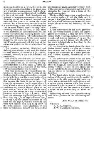
No. 379,346 – Plane (John J. Tower) (1888)

[paiddownloads id=”431″]379346


UNITED STATES PATENT OFFICE.

_________________

JOHN J. TOWER, OF BROOKLYN, NEW YORK.

PLANE.

_________________

SPECIFICATION forming part of Letters Patent No. 379,346, dated March 13, 1888.
Application filed November 1, 1886. Serial No. 217,674. (No model.)

_________________

To all whom it may concern:

Be it known that I, JOHN J. TOWER, of Brooklyn, in the county of Kings and State of New York, have invented an Irnprovement in Planes, of which the following is a specification.

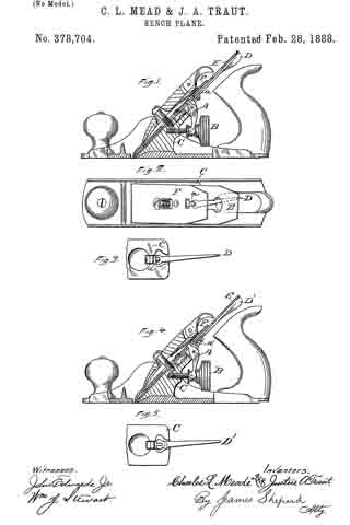
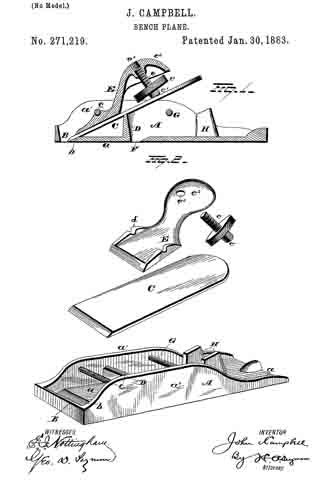
Bench planes are extensively manufactured with wooden handles fastened into a metal plate that is screwed upon the wooden body of the plane, and this plate extends forward of the handle and is provided with vertical flanges, between which the plane-iron is received. Difficulty has heretofore been experienced in attaching the handle in such a manner that the same will not work loose when in use and so that the handle can be disconnected with facility for packing or be rapidly and firmly replaced. I make use of a screw passing through the handle at an inclination to the plane, so as to strengthen the handle, and this screw enters the iron plate so as to clamp the handle thereto, and the bottom portion of the handle is extended forward and passes in between undercut lugs upon the iron plate, so that the weight of the plane when it is lifted by the handle is partially taken upon the undercut lugs, and any tendency to bend the screw is prevented and the thrust upon the handle when the plane is in use is received jointly by the clamping-screw and the undercut lugs.

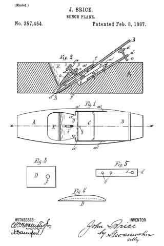
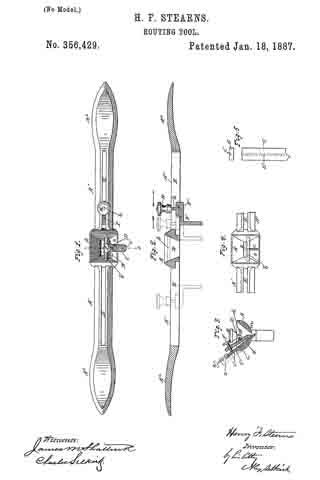
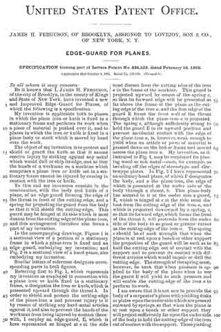
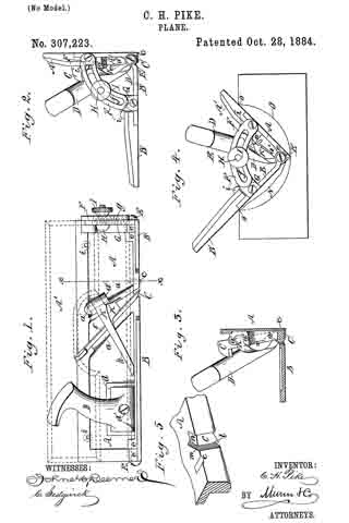
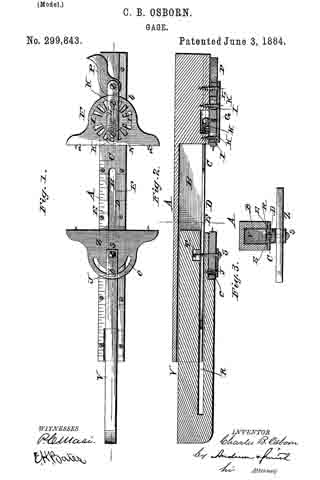
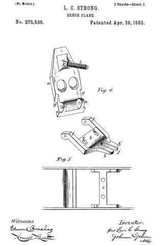
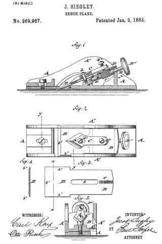
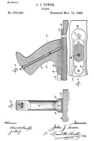
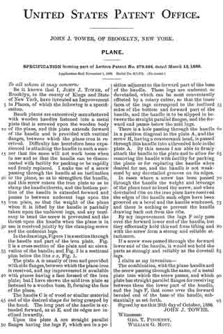
In the drawings, Figure 1 is a section through the handle and part of the iron plate. Fig. 2 is a cross-section of the plate and an elevavation of the handle; and Fig. 3 is a sectional plan below the line x x, Fig. 1.

The plate A is usually of iron and provided with side flanges, between which the plane-iron is received, and my improvement is available with planes having a face formed of the iron plate; but l have shown the said iron plate as fastened to a wooden base, B, forming the face of the plane.

The handle C is of wood or similar material and of the desired shape for being grasped by the hand. The long part of the handle is extended forward, as at E, and its edges are inclined inwardly.

Upon the plate A are straight parallel flanges having the lugs F, which are in a position adjacent to the forward part of the base of the handle. These lugs are undercut or dovetailed, which can be most conveniently effected by a rotary cutter, so that the inner faces of the lugs correspond to the inclined sides of the bottom and forward part of the handle, and the handle is to be slipped in between the straight parallel flanges, and the forward end passes below the said lugs.

There is a hole passing through the handle in a position diagonal to the plate A, and the screw H, having a countersunk head, is passed through this handle into a threaded hole in the plate A. By this means I am able to firmly attach the handle to the plate and to allow for removing the handle with facility for packing the plane or for replacing the handle when desired for use, and the handle is not weakened by any dovetailed grooves on its edges.

In cases where a screw has been passed through the handle the weight and leverage of the plane tend to bend the screw, and when dovetailed ribs on the iron plate have received the edges of the handle such edges have been grooved on a bevel and the handle weakened, and there is nothing to prevent the handle drawing back out from the ribs.

By my improvement the lugs F only pass over the forward lower end of the handle, but they effectually hold this end from lifting and with the screw form a strong and reliable attachrnent.

If a screw were passed through the forward lower end of the handle, it would not hold the parts as strongly and reliably as the dovetail lugs.

I claim as my invention —

The combination, with the plane-handle and the screw passing through the sarne, of a metal plate into which the screw passes, and which plate has straight parallel flanges for receiving between them the lower part of the handle, and the lugs F, that come over the forward beveled end of the base of the handle, substantially as set forth.

Signed by me this 26th day of October, 1886.

JOHN J. TOWER.

Witnesses:
GEO. T. PINCKNEY,
WILLIAM G. MOTT.

No. 378,704 – Bench-Plane (Charles L. Mead And Justus A. Traut) (1888)

[paiddownloads id=”429″]378704


UNITED STATES PATENT OFFICE.

_________________

CHARLES L. MEAD, OF NEW YORK, N. Y., AND JUSTUS A. TRAUT,
OF NEW BRITAIN, CONNECTICUT.

BENCH-PLANE.

_________________

SPECIFICATION forming part of Letters Patent No. 378,704, dated February 28, 1888.
Application filed August 24, 1885. Serial No. 175,142. (No model.)

_________________

To all whom it may concern:

Be it known that we, CHARLES L. MEAD, of New York, in the county of New York and State of New York, and JUSTUS A. TRAUT, of New Britain, in the county of Hartford and State of Connecticut, both citizens of the United States, have invented certain new and useful Improvements in Bench-Planes, of which the following is a specification.

Our invention relates to improvements in adjusting the plane-irons laterally.

In the accompanying drawings, Figure 1 is a vertical section, partly in elevation, of a bench-plane which embodies our invention. Fig. 2 is a plan view of the same with the holding-cap removed. Fig. 3 is a face view of a portion of the frog and the laterally-adjusting lever. Fig. 4 is a vertical section, partly in elevation, showing a modification of our invention; and Fig. 5 is a face view of a portion of the frog and laterally-adjusting lever of the plane represented in Fig. 4.

We have illustrated our improvement as applied to a Bailey plane, in which the cutter is adjusted up and down by means of the lever A and the nut B; but it may be used in connection with planes having different mechanism for adjusting the cutter up and down. At the upper end of the frog C we pivot the laterally-adjusting lever D, the handle of which lies under the upper end of the cutter E. On the short end of this lever there is an upwardly-projecting pin or stud, a, the length of which pin is longer than the thickness of the cutter E and nearly equal to the combined thickness of the cutter E and the cap-iron F. In use this cap-iron and cutter are secured together by a screw in the ordinary manner. The cap-iron F is provided with a T shaped slot, (shown most clearly in Fig. 2,) the transverse portion of which slot receives the upper end of the adjusting-lever A, while that portion of the slot which extends longitudinally with the cap-iron receives the upper end of the pin a. Inasmuch as the cap-iron has but a very slight up and down movement, the slot for this pin can be made quite short. By turning the lever B to the right or left, as may be required, the upper end of the cap-iron and cutter may be carried to either side, so as to bring their edges square with the stock.

In Figs. 4 and 5 we have shown a modification of our invention, in which we have a similar lever, D’, pivoted in like manner to the frog C; but instead of having a pin in its short end said end is slotted, as shown in Fig. 5, and the cap-iron F has rigidly secured to it a pin, a’, which extends downward through the ordinary slot in the cutter and into the slot of the laterally-adjusting lever. In both constructions the laterally-adjusting lever is made to engage directly with the cap-iron, and is connected thereto by a pin-and-slot connection.

We are aware of the patents to Traut, No. 306,877, October 21, 1885; Gage, No. 323,804, August 4, 1885, and Nicht, No. 173,177 , February 8, 1876, and hereby disclaim all that is shown and described in said patents. By our improvements the construction of the laterally-adjusting lever and its connection is so simple as to be produced at the smallest possible cost. It is also as convenient to use as that of any prior plane. In these prior devices when the lever or the fulcrum block on the lever takes into the slot of the cutting-bit the end of the lever or block must be properly fitted to the slot of the cutter, and when a cutter with a slot of different width is employed the adjusting-lever will not fit it. By our improvement different cutters may be used without reference to the width of the ordinary slot in the cutting-bit.

While the Gage patent shows the laterally-adjusting lever connected with the cap-iron, it necessitates the employment of an additional element — viz., the fulcrum block — not required in our combination.

In the Traut and Nicht patents the laterally-adjusting lever bears against the side edges of the slot in the cutter at some considerable distance each side of a longitudinal line passing through the fulcrum-pin. In our device the bearing of said laterally-adjusting lever on the pin which connects its slotted end with the cap-iron is nearly on said longitudinal line, and consequently said lever works with greater ease and less friction and with less wear.

We claim as our invention —

In at bench-plane, the laterally-adjusting lever pivoted to the frog just underneath the cutter and connected directly with the cap-iron by a pin-and-slot connection, the pin of which extends through the slot in the cutter, but does not engage the cutter, substantially as described, and for the purpose specified.

CHAS L. MEAD.
JUSTUS A. TRAUT.

Witnesses:
JAMES SHEPARD,
CHAS B. STANLEY.

No. 368,003 – Spokeshave (James H. Polhemus) (1887)

[paiddownloads id=”424″]368003


UNITED STATES PATENT OFFICE.

_________________

JAMES H. POLHEMUS, OF BROOKLYN, NEW YORK.

SPOKESHAVE.

_________________

SPECIFICATION forming part of Letters Patent No. 368,003, dated August 9, 1887.
Application filed January 25, 1887. Serial No. 225,465. (No model.)

_________________

To all whom it may concern:

Be it known that I, JAMES H. POLHEMUS, of Brooklyn, in the county of Kings and State of New York, have invented a new and Improved Spokeshave, of which the following is a full, clear, and exact description.

My invention relates to an improvement in spokeshaves, and has for its object to provide a tool capable of use as readily in curves of small radius as upon a flat surface.

The invention consists in the construction and combination of the several parts, as will be hereinafter fully described, and set forth in the claims.

Reference is to be had to the accompanying drawings, forming a part of this specification, in which similar letters of reference indicate corresponding parts in all the figures.

Figure 1 is a plan view of my spokeshave, and Fig. 2 is a central transverse vertical section through line x x of Fig. 1. Fig. 3 is a horizontal section through the central portion of my tool, with the clamp removed and the surface of the blade exposed.

At each side of the central portion of the tool A, having the ordinary handles, a, and transversely the said tool, vertical ears B are formed, provided near their upper edge with a segmental slot, b, and a parallel integral transverse offset, C, upon their inner face at the base, which offset is more or less concaved at its outer end.

In the body D of the tool, intervening the ears B, a more or less V-shaped central recess, d, is produced, which recess is out entirely through said body at the inner end thereof, as illustrated at d’ in Figs. 1 and 3. Within the recess d a pin, e, is secured, upon which pin an angle-lever, E, is pivoted at the intersection of its arms, the short arm of said lever being adapted to reciprocate in the recess d, and having a stud, F, made integral with its upper face near the end, the long arm of said lever being provided with a thumb-rest, f.

A knife, G, having a central slot, g, is made to slide in the body surface D between the transverse offsets C of the ears B. The knife G is also provided with a series of small rectangular slots, H, arranged to the rear of the large slot g, in central alignment therewith, about the sixteenth of an inch intervening each of said small slots, and also the foremost one and the large slot g. When the knife is inserted, as aforesaid, the stud F upon the angle-lever is made to enter the first or foremost rectangular slot H, as shown in Figs. 2 and 3. As the knife becomes narrowed by sharpening and use, the remaining slots H may be brought into contact with the stud F.

The object of the lever-connection with the knife is to adjust the knife-edge, as in a plane, the desired distance over the front edge of the body surface D.

A clamping-plate, K, of substantially the same shape as the knife, provided with an outer beveled edge, k, and a central elongated slot, k’, is made to rest upon the knife G, clamping the same in a given position by means of a screw, L, which, passing through the slot k’ of the clamp-plate and the large slot g of the knife, is screwed into the body D, as shown in Fig. 2.

A guide, M, consisting of the longitudinal bar m, having a flat under surface, m’, and more or less round corners, m2, and provided with integral arms m3 at right angles thereto, is adjustably held within the ears B by thumb-screws N, entering the slots b in said ears and also the arms m3 of the guide at their ends. When the guide M is thus positioned, the flat under surface m’ thereof is normally in the same horizontal plane with the under flat surface n of the body D. A space is, however, made to intervene the opposing edges of the said body D and the guide.

In operation, by pressing with the thumb against the lever E the knife is adjusted as desired and set by the body-screw L. If a plain surface or curve of large radius is to be dressed, the arms of the guide M are secured in the upper corners of the segmental recesses b, as shown in Fig. 2. In this position the device acts as an ordinary tool of its kind. When, however, it is desired for use upon a curve of small radius, the arms of the guide are carried as far down the slot as thought proper, which action throws the under surface of the guide at an angle to the flat under surface of the body, permitting a manipulation of the tool in short curves or in apertures large enough to admit the tool.

Having thus described my invention, what I claim as new, and desire to secure by Letters Patent, is —

1. In a spokeshave, the combination, with the body D, provided with the ears B, having curved slots b, and the blade adjustable on the upper face of the body D between said ears, of the guide M, consisting of the longitudinal bar m, pivotally connected at its ends to the ears B adjacent to the lower end of the blade, and formed with the arms m3, having threaded apertures in their upper ends, and the set-screws N, passing through the slots b into said apertures, substantially as set forth.

2. In a spokeshave, the combination, with the body D and a guide, of the blade G, having slots H g, the lever E, pivoted to the body and having a stud, F, entering the slot H, the clarnping-plate K, having a. slot, k’, and the set-screw L, extending through the slots k’ g into the body D, substantially as set forth.

3. A spokeshave comprising the body D, having the V-shaped slot d’ in its upper face, the ears B B, having slots b, the U-shaped guide M, pivoted at the lower ends of its side arrns, m3, to the lower ends of the ears, and set-screws passed through the slots b into the upper ends of said arms, the lever E, pivoted at e within recess d’, and having a pin, F, the blade G, having a slot, g, and a series of slots, H, into one of which pin F projects, the clamping-plate K, having a slot, k’, and the set-screw L, passed through the slots k’ g into the body, substantially as set forth.

JAMES H. POLHEMUS.

Witnesses:
J. F. ACKER, Jr.,
G. H. POLHEMUS.

No. 357,454 – Bench-Plane (John Brice) (1887)

[paiddownloads id=”420″]357454


UNITED STATES PATENT OFFICE.

_________________

JOHN BRICE, OF SANDY HILL, NEW YORK.

BENCH-PLANE.

_________________

SPECIFICATION forming part of Letters Patent No. 357,454, dated February 8, 1887.
Application filed March 16, 1886. Serial No. 195,420. (Model.)

_________________

To all whom it may concern:

Be it known that I, JOHN BRICE, a resident of Sandy Hill, in the county of Washington and State of New York, have invented certain new and useful Improvements in Bench-Planes; and I do hereby declare that the following is a full, clear, and exact description of the invention, that will enable others skilled in the art to which it appertains to make and use the same, reference being had to the accompanying drawings, and to the letters of reference marked thereon, which form a part of this specification.

My invention relates to improvements in bench~planes, and its object is fully explained in connection with the drawings.

The invention consists of the novel construction and combination of parts hereinafter described, and pointed out in the claims.

Figure 1 of the drawings is a top plan view of my improved plane. Fig. 2 is a vertical longitudinal section taken at the broken line x x in Fig. 1. Fig. 3 is a top plan view of my improved locking-lever. Fig. 4 is a side view of same. Fig. 5 is a plan view of attachment d detached.

Similar letters refer to similar parts in the several figures therein.

Numerous devices have been heretofore constructed for angularly adjusting the bit of a bench-plane and for securing the same in place in its frame or stock. They have generally been complicated in structure and expensive of manufacture, requiring special and differing forms of structure in the stock, the latter being generally made of metal.

In the construction of my improved device I am able to make use of the old and well-known wooden stock so generally in use, as well as the bit, or bit and back plate, used in connection therewith, and thus greatly improve such planes with very little expense.

My improved planes can also, when desired, be made wholly of metal or any other desirable material.

A is the stock, made in the well-known form usually adopted for wooden stocks, having the chip-opening E, inclined bit-abutment F, and upwardly-widening rearwardly-inclined side recesses, a’ a’, forming inclined ledges a a on each side of the chip-opening.

The bit B, which has a back plate, C, secured thereto by a set-screw, g, adjustable in its slot b’, is inserted through the opening in the usual manner, as shown.

Instead of driving a wedge down between the bit or plate C and the projecting ledges a a, to bind the bit in place, as has been done heretofore in such stocks, I make use of the locking-lever D, preferably metallic, and in the form of a plate convened on its upper side, substantially as shown.

I slide the lever down between the back plate, C, and the ledges a to about the position shown in Figs. 1 and 2.

The side of the lever contiguous to the plate C may have its surface plane or concave, as shown by dotted line in Fig. 4; but the opposite side contiguous to the ledges is convexed. The degree of convexity may be varied as desired.

At or near one end of the lever I provide the aperture f, preferably threaded, and adapted to receive the threaded adjusting screw b, the screw passing down through the aperture and resting upon the bit or its plate C.

When desired, a threaded nut, n, (shown by dotted lines,) may by employed, when it will not be necessary to thread the aperture in the lever.

By means of the adjusting-screw the upper end of the lever can be forced away from the plate C, the lower end of the screw resting upon the plate, and the lever traveling up the thread of the screw until the parts are securely locked in place, the central portion of the convexed lever ending a fulcrum upon the ledges a a, and the lower end of the lever bearing upon the lower end of the bit or its plate. I am able also to secure an angular adjustment of the bit by means of the attachment or plate d, extending above the top of the stock, provided with the adjusting-screw e, threaded to fit the threaded aperture i, having a head, e’, on which the bit has bearing. This attachment is preferably countersunk in a longitudinal recess, a”, in the upper or rear portion of the abutment F, to occupy a position about parallel with the bit, and may be secured by screws d’, passing through apertures j, as shown.

The upper end or head of the screw bears against the lower side of the bit, and when operated forces the bit up to the desired angle, the screw b being turned back, as required.

The convexity of lever D permits the angular adjustment of the bit to any desired degree without impairing the perfect operation and effectiveness of the lever as a locking device.

I am thus able to produce a new and improved plane by adding the loclring-lever D, with screw b, and the attachment d, with screw e, to a common and well-known device.

I do not broadly claim an angularly-adjustable bit nor a bit-locking lever.

What I claim as new, and desire to secure by Letters Patent, is —

1. The combination of the stock A, formed with a chip-opening, E, inclined rear abutment, F, having correspondingly-inclined longitudinal recess a”, upwardly-widening inclined side recesses, a’ a’, forming inclined front abutments, a a, projecting into the chip-opening, the fixed plane plate d, secured in the longitudinal recess and projecting above the stock, an adjusting-screw, e, inserted in the projecting portion, having a head, e’, a bit, B, supported on the inclined rear abutment and on the head of the adjusting-screw, the back plate, C, adjustably secured to the bit, and the lever D, located at the rear of the chip-opening, having a convex upper side bearing against the front abutments, its lower end bearing on the lower end of the back plate, and an adjusting-screw in the upper end of the lever bearing on the middle portion of the back plate, the bit, back plate, and lever all being of the sanie width and the side recesses being common to all, substantially as shown and described.

2. The combination of the stock A, formed with a chip-opening, E, longitudinal recess a”, and upwardly-widening inclined side recesses, a’ a’, forming inclined front abutments, a a, projecting into the chip-opening, the fixed plane plate d, having an adjusting-screw, e, a bit, B, a back plate, C, and the lever D, located at the rear of the chip-opening, having a convex upper side bearing against the front abutments, its lower end bearing on the lower end of the back plate, and an adjusting-screw in the upper end of the lever bearing on the middle portion of the back plate, the bit, back plate, and lever all being of the same width and occupying the side recesses common to all, substantially as shown and described.

In testimony whereof I have hereunto set my hand this 12th day of March, 1886.

JOHN BRICE.

Witnesses:
J. RADCLYFFE BRICE,
ELISHA D. BAKER.

No. 356,429 – Routing-Tool (Henry F. Stearns) (1887)

[paiddownloads id=”419″]356429


UNITED STATES PATENT OFFICE.

_________________

HENRY F. STEARNS, OF SARATOGA SPRINGS, NEW YORK, ASSIGNOR OF
ONE-HALF TO EDMOND G. RAWSON, OF SAME PLACE.

ROUTING-TOOL.

_________________

SPECIFICATION forming part of Letters Patent No. 356,429, dated January 18, 1887.
Application filed June 22, 1885. Serial No. 169,356. (No model.)

_________________

To all whom it may concern:

Be it known that I, HENRY F. STEARNS, a citizen of the United States, residing at Saratoga Springs, in the county of Saratoga and State of New York, have invented certain new and useful Improvements in Routing-Tools for Workers of Wood, of which the following is a specification.

My invention relates to improvements in routing-tools in which the stock is provided with a mouth having on one of its sides a way for holding the cutting-tool and a wedging-piece and an adjustable gage working in the arms of the tool, all of which I will hereinafter particularly describe and set forth; and the objects of my invention are to provide in a routing-tool adjustable and interchangeable cutting-tools, which will be securely held from shifting in the mouth of the tool and have the gaging devices adapted to be variously adjusted and set at either right or left hand side of the cutting-tool and at any desired distance therefrom as the work to be done may require. I attain these objects by the mechanism illustrated in the accompanying drawings, in which —

Figure 1 is a view of the tool from above. Fig. 2 is a longitudinal sectional elevation. Fig. 3 is a cross-section taken at line 1 in Fig. 1. Fig. 4 is a view of the mouth of the stock with the cutting-tool and wedge removed, and showing the tool-guiding way. Fig. 5 is a plan view of a cutting-tool and an end view of the same, showing the coacting way made therein.

The same letters of reference refer to like parts throughout the several views.

The stock A, arms A’, and handles A2 A2 of this tool may be made in one piece of malleable iron, or be made of wood and iron combined, if preferred. The stock A is made with a gradually-contracting mouth, B. Across the upper portion of this mouth, and arranged slightly to one side of the center of its width and running longitudinally in direction of arms A’, is bar b, preferably made solid with the end walls of said mouth, or securely fixed therewith. Made with the rear side wall, a, of this mouth is the way c, which is shown in Figs. 3 and 4 to project a short distance past the plane of said rear wall.

C is the cutting-tool, made with any form of cutting bit or edge usually employed for grooving, channeling, beading, or forming moldings, or for incising. Made central in the width of this cutting-tool and in its rear side from its upper end, or near the cutting bit or edge, is the way c’, corresponding in size and form with way c, made with the rear wall, a, of mouth B, so that the former will receive the latter and permit the shank of the tool to have a full bearing on the surface of wall a of the mouth of the tool. These ways may be made to be reversed in their respective forms by making that in wall a of mouth B in the form of a groove instead of a projection, as shown, and that in tool C in the form of a projection instead of a groove, as shown. These ways c c’ in the respective pieces co-operate together to hold the cutting tool or blade C from shifting or being moved out from its normal set position in the mouth of the stock, and allow a variety of tools or blades, C, of differing widths to be employed within mouth B without the least liability of shifting when the tool is being operated.

D is the wedge, having a shallow groove, d, running across its front side, as shown in Fig. 3, for engagement with holding-bar b. The lower end of this wedge is made with an incline, as shown in the same figure, so as to permit an opening between the tool or blade below and the front wall of mouth B, for passage of the shavings from the cutting bit or edge of the blade C. In the upper end portion of this wedge D is made a screw-threaded hole, into which works the set-screw f by which, through wedge D, the cutting tool or blade C is securely held in its adjusted position and length of projection below the sole or face m, of the stock, which face is curved in its surface. Made in arms A’ A’ are slots E E, extended to any preferred distance from stock A toward handles A2.

F is an adjustable gage-lip provided with a projection, g, which nicely fits in slots E, for holding with the same to prevent the gage-lip from shifting sidewise. This projection is made with tail-piece F’ of the gage-lip, and has projecting upward from it the screw-threaded stem h. Nicely fitting this stem h is the screw-threaded finger-nut H, for securing this gage-lip at any point distant from the cutting tool or blade C. This gage-lip and its holding device are adapted to be used in the slot E of either of the arms A’, as may be required for right or left hand work.

By my above described improvements I obviate the use of several different bodies of routing-tools as heretofore required by carriage-makers, cabinet-makers, and other workers of wood for different operations or kinds of work, and with a variety of cutting blades or tools, C, provided each with a suitable form of cutting edge or bit, a workman can form in the wood on straight or curved lines, and on the right or left hand edges of the pieces, grooves, channels, beads, moldings, flutings, or other raised or sunken surfaces, as may be required.

The mouth of the router, being arranged to be vertically over the cutting-bit of tool C, will deliver the shavings upward from the same in a free manner instead of in a forward direction, as is usual in routers heretofore made, and the shavings will be freely delivered from the cutting-bit and without the least liability of choking the tool, as heretofore. The coacting ways c c’, made with the rear side wall of the mouth of the stock and the rear side of the shank of the cutting-tool C, operate to hold that tool firmly from shifting in any direction, and the bar b, operating with the groove d of wedge D, holds the latter from moving in either direction end wise, While the wedge D, with the set-screw f operates to hold the tool or blade C secure to its place, with its cutting-edge projecting below the sole of the stock to the point adjusted to without the least liability of its being raised, and also allows this cuttlng-blade to be readily set to cut deeper from time to time, as may be required in the progress of the work.

The spokeshave-blade can readily be applied and be firmly held and shifted in either direction in relation to the month of the stock A. The stock, with its slotted arms and handles, operating to serve as the body of a spoke-shave, being well adapted to receive the above-described shaving-blade S, obviates the use and expense of a special and individual stock, as heretofore required.

The stock A and its mouth B may be made of any suitable length, so as to receive two or more cutting-tools, C, for grooving or incising or beading two or more surfaces at a time, as may be preferred. The curved surface of face m of the stock running from one side to the other enables the operator, by slightly turning the stock, to cut with a greater or less depth into the wood, and thereby obviates the necessity of setting the cutting-blade C (for making different depths of cuts) several times before finishing the work being done.

If preferred, a small bracket, z, made with the rear side of the stock, and provided witli a set-screw, x, working in its head end, and its lower end working in a small sleeve attached to the upper end of the tool C and held by a key, may be employed ibr raising or lowering the tool, as is the practice with irons in planes.

Having described my invention, what I claim, and desire to secure by Letters Patent, is —

In a routing-tool, the combination, with a stock provided with similarly-slotted arms, which are extended in opposite directions from the tool mouth, of an adjustable gage-lip, which is provided with a screw-threaded stem and nut and constructed to be used interchangeably in said slotted arms, a cutting-blade which is provided on its rear side with the way c’, which engages with way c, made with the rear side wall of tool-mouth B, and the mechanism described for adjusting and securing said cutting blade in said tool-mouth, substantially as and for the operations and purposes set forth.

HENRY F. STEARNS.

Witnesses:
A. N. SHEPHERD,
W. A. PIERSEN.

No. 336,222 – Edge-Guard For Planes (James H. Ferguson) (1886)

[paiddownloads id=”406″]336222


UNITED STATES PATENT OFFICE.

_________________

JAMES H. FERGUSON, OF BROOKLYN, ASSIGNOR TO
LOVEJOY, SON & Co., OF NEW YORK, N. Y.

EDGE-GUARD FOR PLANES.

_________________

SPECIFICATION forming part of Letters Patent No. 336,222, dated February 16, 1886.
Application filed October 3, 1885. Serial No. 178,870. (No model.)

_________________

To all whom it may concern:

Be it known that I, JAMES H. FERGUSON, of the city of Brooklyn, in the county of Kings and State of New York, have invented a new and Improved Edge-Guard for Planes, of which the following is a specification.

My invention is applicable both to planes in which the plane iron or knife is fixed in a stationary frame and performs its work when a piece of material is pushed over it, and to planes in which the iron or knife is fixed in a plane body or stock which is moved by hand over the work.

The object of my invention is to protect and shield or guard the knife so that it cannot receive injury by striking against any metal which would dull or chip its edge, and so that the hands of a workmen on a machine which comprises a plane iron or knife set in a stationary frame cannot be injured by coming in contact with the iron or knife.

To this end my invention consists in the combination, with the body and knife of a plane, of an edge-guard forming the edge of
the throat in front of the cutting-edge, and a spring for projecting the guard from the body so that it will shield the cutting-edge. This guard may be hinged at its side which is most distant from the cutting-edge of the plane-iron, and this arrangement therefore also forms a part of my invention.

In the accompanying drawings, Figure 1 is a sectional view of a portion of a stationary frame in which a plane-iron is fixed and an edge-guard, embodying my invention; and Fig. 2 is a sectional view of a hand-plane, also embodying my invention.

Similar letters of reference designate corresponding parts in both figures.

Referring first to Fig. 1, which represents my invention as employed in connection with a plane iron or knife fixed in a stationary frame, a designates the iron or knife, which is presented upward through the throat b. In order to shield and protect the cutting-edge of the plane-iron a and prevent injury to it by reason of striking any hard-metal articles against it, and also to prevent the hands of the workmen from being injured by contact therewith, I employ an edge-guard, E, which is here represented as hinged at e at the side most distant from the cutting-edge of the iron a in the frame of the machine. This guard is projected upward by means of the spring c, so that its forward edge will be presented as far above the frame of the plane as the cutting-edge of the iron a, and the free edge of the guard E forms the front wall of the throat through which the plane-iron a is projected. The spring c, although sufficiently strong to hold the guard E in its upward position and prevent accidental contact with the edge of the plane-iron a, is, however, weak enough to yield when an article or piece of material is pressed down on the bed or frame and moved across the plane-iron a. My invention. as illustrated in Fig. 1, may be employed for planing wood or soft metal — such, for example, as beveling off the edges of stereotype and electrotype plates. In Fig. 2 I have represented an ordinary hand-plane, of which F designates the body, and a the plane-iron, the edge of which is presented at the under side of the body through a throat, b. This plane-body has secured in it at the under side a guard, E, which is hinged at e at the side most distant from the cutting edge of the iron a, and which is projected downward by a spring, c, so that its forward edge, which forms the front of the throat b, will protrude from the under side of the body to as great or greater extent as the cutting-edge of the iron a. The spring c should be of such strength that when the plane is at rest upon a bench or other support the projection of the guard will be such as to hold the cutting-edge out of contact with the support and to prevent its contact with different articles which would impair or dull the cutting-edge. The strength of the spring must, however, be such that when pressure is applied to the body of the plane when in use the guard E will yield to such pressure and will enable the cutting-edge of the iron a to perform its work.

I am aware that it is not new to provide the body of a carpenter’s plane with yielding disks or plates upon the under side which are pressed outward by springs, so that when the plane is at rest upon a bench or other support they will project sufficiently far upon the under side of the body to hold the cutting-edge of the iron out of contact with the support. These yielding disks or plates are, however, remote from the throat of the plane, and do not perform the function of my edge-guard E in protecting the edge of the cutting iron or knife, as they do not form the edge of the throat in front of the cutting-edge.

What I claim as my invention, and desire to secure by Letters Patent, is —

1. The combination, with the body and knife of a plane, of an edge-guard forming the edge of the throat of the cutting-edge, and a spring for projecting the guard from the body so that it will shield the cutting-edge, substantially as herein described.

2. The combination, with the body and knife of a plane, of an edge-guard forming the edge of the throat in front of the cutting-edge and hinged at its side which is most distant from the cutting-edge, and a spring for projecting the guard from the body so that it will shield the cutting-edge, substantially as herein described.

JAMES H. FERGUSON.

Witnesses:
FREDK. HAYNES,
HENRY McBRIDE.

Correction in Letters Patent No. 336,222.

It is hereby certified that in Letters Patent No. 336,222, granted February 16, 1886, upon the application of James H. Ferguson, of Brooklyn, N. Y., for an improvement in “Edge-Guards for Planes,” certain words were erroneously omitted in printing the specification, which should be supplied, to wit: In line 11, page 2, after the word “throat” the words in front should be inserted; and the Letters Patent should be read with this correction therein to conform to the record of the case in the Patent Office.

Signed, countersigned, and sealed this 23d day of February, A. D. 1886.

[SEAL.]

H. L. MULDROW,
Acting Secretory of the Interior.

Countersigned:
M. V. MONTGOMERY,
Commissioner’ of Patents.

No. 311,136 – Bench-Plane (Charles L. Mead) (1885)

[paiddownloads id=”523″]311136


UNITED STATES PATENT OFFICE.

_________________

CHARLES L. MEAD, OF NEW YORK, N. Y., ASSIGNOR TO
THE STANLEY RULE AND LEVEL COMPANY, OF NEW BRITAIN, CONNECTICUT.

BENCH-PLANE.

_________________

SPECIFICATION forming part forming part of Letters Patent No. 311,136 , dated January 20, 1885.
Application filed June 16, 1884. (No model.)

_________________

To all whom it may concern:

Be it known that I, CHARLES L. MEAD, a citizen of the United States, residing at New York, in the county of New York and State of New York, have invented certain new and useful Improvements in Bench-Planes, of which the following is a specification.

My invention relates to improvements in bench-planes; and the object of my invention is to produce a simple and efficient mechanism for adjusting the cutting-edge of the bit to square it with the stock. I attain this object by the simple construction illustrated in the accompanying drawings, in which —

Figure 1 is a side elevation of my improved bench-plane. Fig. 2 is a sectional view, partly in elevation, on line x x of Fig. 1. Fig. 3 is a sectional partial view on line y y of Fig. 2. Fig. 4 is a detached view showing the under side of the frog.

It is often difficult to grind the cutting-edge of a plane-bit exactly square, and consequently when set in place it does not stand square with the stock. In such cases the bits have been adjusted by rapping them edgewise from side to side with a hammer. A prior patent shows a mechanisrn for adjusting the bit edgewise to bring its end square with the stock, in which the under side of
the bit was slotted at its lower end and the bit was pivoted by the cap-screw. Such an adjusting mechanism is hereby disclaimed.

Aside from the addition of the adjusting-screw a, traveling block b, and the necessary modifications for securing them in place, my improved plane is the same as ordinary bench-planes. The particular plane I have taken for illustration is known to the art as “Bailey’s Patent Plane.” I provide the frog or seat A with lugs c c, which lugs are provided with smooth-bored holes at points a’ a’, into which I insert the adjusting-screw a, said holes forming bearings for the ends of the adjusting-screw. Upon the adjusting-screw a, I have placed the nuts d d, which nuts will allow the adjusting-screw a to rotate freely upon its axis, but will not allow the adjusting-screw to move longitudinally. Upon the adjusting-screw a, I have arranged a traveling block, b, said block being provided with a threaded hole, which receives the adjusting-screw a. I have provided the traveling block b with an upwardly-extending projection, f, whose height is about equal to the thickness of the cutter which engages with the ordinary slot, g, of the plane bit or cutter. The traveling block moves longitudinally in a slot formed in the frog. The bit or cutter and cap-iron of the plane are set in their places upon the frog or plane-seat in the ordinary manner, care being taken to have the engaging projection f of the traveling block b project upward into the ordinary longitudinal slot of the bit. The holding-cap B is then put into its proper place and clamps the bit and cap-iron firmly against the frog or plane-seat, said holding cap pressing then at each end. The point of pressure at the lower end of the cap is the point where the bit will pivot when its upper end is moved edgewise. When the parts are thus assembled in place ready for use, in order to adjust the bit edgewise to bring its edge square with the stock, it is only necessary to turn the adjusting-screw a, one way or the other, as the case may be, which readily adjusts the bit or cutter laterally and brings its edge square with the stock, as shown.

I am aware that a prior patent for bench-planes shows a mechanism for adjusting the cutting-bits endwise, which consists of a screw and a transverse slide having an oblique slot, which receives a projection from the under side of a second slide for carrying the plane-irons up and down, and the same is hereby disclaimed.

I claim as my invention —

In a bench-plane, the herein-deseribed mechanism for adjusting the cutting-bit laterally, consisting of the adjusting-screw a, the traveling block b, having the upwardly-extending projection f for taking into the longitudinal slot of the cutting-bit, said screw and block located at the upper end of the frog, and operating to adjust the cutting-bit laterally by the direct action of the block against the side walls of the slot in said bit at its upper end, substantially as described, and for the purpose specified.

CHARLES L. MEAD.

Witnesses:
H. S. WALTER,
H. C. HINE.

No. 310,349 – Chamfering-Plane (Richard Vanwike Wicks) (1885)

[paiddownloads id=”381″]310349


UNITED STATES PATENT OFFICE.

_________________

RICHARD VANWIKE WICKS, OF BROOKLYN, NEW YORK.

CHAMFERING-PLANE.

_________________

SPECIFICATION forming part of Letters Patent No. 310,349, dated January 6, 1885.
Application filed April 29, 1884. (Model.)

_________________

To all whom it may concern:

Be it known that I, RICHARD VANWIKE WICKS, of Brooklyn, in the county of Kings and State of New York, have invented certain new and useful lmprovements in Chamfering and other Planes, of which the following is a full, clear, and exact description.

This invention has for its object the production of a plane to be used by carpenters and others for making “stop” chamfers, rule-joint and other moldings — that is, chamfers or moldings which are required to stop short of the whole length of the work or piece of wood to be dressed — as, for instance, when required to form a square base on the end of a frame or other piece of timber. To do this kind of stop-work, planes of special construction for cutting stop-chamfers have before been designed and used; but they essentially differ from the plane hereinafter described, and it generally has been and still is customary to cut away with the chisel the wood at a distance from where the chamfer or molding is required to be stopped, and then to work an ordinary chamfering or molding plane up to such cut portion, and afterward to dress or finish with the chisel, sandpaper, or otherwise. This is not only tedious, but expensive, on account of the labor involved, especially where a large amount of such work has to be done. My improved plane effectually accomplishes the work, without any such chiseling or cutting away, by the simple or direct act of running or passing the plane over the work. The invention coniprises a peculiarly-constructed stock having an enlarged oblique opening down through it for the introduction of a guide corresponding with the shape of the chamfer or molding, and the cutter also having a longitudinal groove in its base corresponding in transverse section with the angular edge of the wood before the chamfering or molding guide and cutter are passed over it, and which groove is of a depth in rear of the cutter to receive the part not designed to be dressed by the cutter up within it. It likewise comprises various details of construction for separately adjusting the guide and cutter, for clamping or holding and releasing the knife or cutter, and for otherwise providing for the general and special action ofthe tool, substantially as hereinafter described.

Reference is to be had to the accompanying drawings, forming part of this specification, in which similar letters of reference indicate corresponding parts in all the figures.

Figure 1 represents a longitudinal vertical section on the line x x in Fig. 2 of a plane embodying my invention. Fig. 2 is a plan of the same; Fig. 3, a transverse section on the line y y in Fig. 1, looking in direction of the arrow in; Fig. 4, a section on the irregular line z z in Fig. 1, and Fig. 5 a section on the line in 2: in Fig. 1. Fig. 6 is a face view of a knife or cutter for making a stop rule-joint form of molding instead of a plain or flat chamfer, as provided for by the cutter and guide shown more particularly in Figs. 1 and 3; Fig. 7, a face view of a guide-plate adapted to the rule-joint cutter, and Fig. 8 a longitudinal view of a piece of rule-joint work as produced by the use in the tool of the cutter and guide shown in Figs. 6 and 7.

A indicates the stock of the plane, made either of iron or wood, but preferably metal, with an enlarged oblique opening, b, up through it, inclining forwardly in a downward direction. The base of said stock is constructed to form or leave an enlarged angular (preferably right-angular) recess or groove, c, centrally up within it throughout its length, the same corresponding in transverse section with the angular adjacent longitudinal marginal portions of the piece of wood to be chamfered or molded before said portions are so reduced or fashioned.

B is a guide or shoe adjustable up and down within the oblique opening b in the stock, and which may be directed in its movement by correspondingly inclined or oblique ribs d d, working in grooves e e in the side walls of the opening b. The lower face of this guide or shoe is flat or straight and parallel with the lower side margins of the stock, and is dovetailed, as at f f, to receive within and along it a face piece or plate, g, shaped on its under surface to accord with the configuration of the chamfer or rnolding to be made. In Figs. 1 and 3 it is represented as flat on its face, and the knife or cutter C, which is arranged in the rear of it, is straight on its cutting-edge to correspond, for the purpose of making a flat or plain stop-chamfer on the adjacent marginal longitudinal portions of the piece of wood to be worked, while in Figs. 6 and 7 the under surface of the face-piece g and the acting edge of the cutter C are shaped to produce a stop rule-joint molding, h, (see Fig. 8,) on the wood D to be worked. Other shaped moldings will require different guiding face plates or pieces and cutters. When attached, the face-piece g becomes a portion of the guide B, and it may be held from moving by a set-screw, i. By making it removable, however, as likewise the cutter, which is also carried by said guide, the same guide or shoe B may be used in connection with different face pieces or plates and cutters, according to the shape of molding required. The knife or cutter C is passed down within the guide B against its inclined back, which should be cut away below, as at k, so as not to interfere with or project down into the longitudinal groove b in the bottom of the stock. The cutting edge of the knife, when the latter is adjusted for work, projects any desired distance below the under surface of the guiding-plate g, according to the thickness of the shaving to be made, and stands at some little distance in rear of said face-plate, leaving a sight-aperture and shaving-clearance, l, between said plate and cutter. The whole guide or shoe B is adjusted up or down, according to the width of the chamfer or molding to be made, by means of a screw, E, fitted to turn within and through a box-like projection, m, on the back of the guide; but it has no longitudinal movement therethrough, being restrained by cross-pins n n or otherwise, and it screws at its lower end portion within or through the part r of the stock, and may be steadied below by a side set-screw, s, Fig. 5. The upper end of said screw is fitted with a knob or head, a’, which bears down on a knob or head, b’, of a second screw, G, made hollow and receiving the shank of the screw E through it. This second screw, G, works through a nut, c’, which has connected with it, by side pin or pins and slot or slots, s’, a yoke, d’, pivoted, as e’, to the box-like projection m on the guide B, and fitting at its outer end in any one of a series of holes, f’, in the cutter, whereby on turning the screw G by its head b’ the cutter maybe raised or lowered to especiaily adjust its amount of cut. Its general adjustment, as wear may require, is provided for by changing the fit of the yoke d’ from one of the holes f’ to another. The concentric arrangement of the two screws E and G the one within and through the other is very compact and convenient for separately adjusting the guide or slice B and the cutter C, carried by said guide. The cutter C is held to its place on the back of the guide B and in engagement with the adjusting device or yoke d’ with facility for disengagement and removal, when required, by means of a front plate or arm. H, in slotted pivoted side connection at g’ g’ with the guide or shoe B, and a locking arm or eccentric, I, pivoted at h’ on the upper end of said arm, and having its handle h2 arranged to shut down out of the way, said cam bearing, when closed, against a flexible strip or spring, i’, attached at its one end to the arm H and lying at its other end on the cutter. On the front top portion of the stock A is a handle, J, for one hand of the workman to hold, while his other takes hold of the back portion of the plane to guide and work the tool.

In using the plane to make a stop-chamfer or stop rule-joint or other stop molding, the cut is made direct from where the chamfer or molding, as at l’, Fig. 8, stops on the wood, the plane being pressed and held thereon with the sides of its longitudinal base groove c resting on or against the two adjacent longitudinal marginal portions of the piece of wood, and the cutter C, by the manipulation of the plane, made to enter the wood at l’, or where the chamfer or molding is designed to stop, the clearance-aperture l in front of the cutter enabling the operator to see the exact place at which he should start. The plane is then worked forward away from such starting-point, and the operation repeated till the wood has been sufliciently reduced to make the necessary chamfer or molding, the operator always starting from the same place and pressing down on the plane, which receives within the angular groove c of its base, in rear of the cutter, the correspondingly-shaped base or stopped part of the work, which groove provides for the starting of the chamfering or molding at any point in the length of the strip or piece of wood, and for making a stop charnfer or molding without any chiseling or other cutting than that done by the plane in making the chamfer or molding.

Having thus described my invention, what I claim as new, and desire to secure by Letters Patent, is —

1. The combination, with the stock A, having an oblique opening, b, up through it, and a longitudinal angular recess or groove, c, in its base, shaped to conform to the adjacent longitudinal marginal portions of the wood to be worked, of the guide and cutter-holder B, having a lower face-piece made to conform to the shape of the chamfer or molding to be produced, and adjustable along with the cutter, of like shape on its cutting-edge, down through said oblique opening and into the longitudinal angular groove c, which it crosses, substantially as and for the purposes herein set forth.

2. The removable guiding face piece or plate f, in combination with the adjustable guide or shoe B and the separately-adjustable cutter C, carried by said guide or shoe, essentially as shown and described.

3. The screws E and G, arranged to pass longitudinally one through the other, in combination with the stock A, the guide or shoe B, and the cutter C, for separate and collective adjustment of said guide or shoe and cutter, substantially as specified.

RICHARD VANWIKE WICKS.

Witnesses:
A. GREGORY,
C. SEDGWICK.

No. 307,223 – Plane (Charles H. Pike) (1884)

[paiddownloads id=”377″]307223


UNITED STATES PATENT OFFICE.

_________________

CHARLES H PIKE, OF WEST TROY, NEW YORK.

PLANE.

_________________

SPECIFICATION forming part of Letters Patent No. 307,223, dated October 28, 1884.
Application filed June 28, 1884. (No model.)

_________________

To all whom it may concern:

Be it known that I, CHARLES H. PIKE, of West Troy, in the county of Albany and State of New York, have invented a new and Improved Wood-Plane, of which the following is a full, clear, and exact description.

The object of my invention is to provide a simple, efficient, and inexpensive tool to be used by wood-workers for economically dressing out the hollow faces of pieces of lumber or timber used in making round or curved work, such as tubes, stair-cylinders, or round or curved patterns to make castings from, and a large variety of crooked or curved work.

The invention consists of a woodplane having a stock made in two parts, hinged to each other so as to be adjusted and fastened at any required angle with each other, for causing the cutter held at the angle of the two part stock to dress the roughed-out work to the required transverse curve as the plane is rocked axially while being passed backward and forward over the work, with the faces of the opposite parts of the stock resting on trued edges of the work.

The invention includes, also, particular construction and combination of parts of the plane, all as hereinafter fully described and claimed.

Reference is to be had to the accompanying drawings, forming a part of this specification, in which similar letters of reference indicate corresponding parts in all the figures.

Figure 1 is an outside longitudinal sectional elevation of my improved plane. Fig. 2 is a front end view thereof. Fig. 3 is a cross-sectional elevation on the line x x, Fig. 1. Fig. 4 is a front view illustrating the manner of using the plane, and Fig. 5 is a detail perspective view.

I make the plane-stock in two parts or sections — the part A, to which the cutters C c and handle D are held, and a part, B, which is jointed to the part A lengthwise on pivots E, which pass through lugs e e formed at the ends of the parts A B. At the front end of the plane the parts A B of the stock have fixed curved or segmental arms F G, respectively, which arms are centrally slotted, as at f, and the arms are so shaped and located that their slots coincide always, irrespective of the angle at which the parts A B are set relatively to each other. A headed screw-bolt, H, is passed through the slots of both arms, F G, and has a suitable thumb-nut, I, by which the arms may be bound tightly to each other to hold the parts A B of the stock at any relative angle at which they may be set.

I prefer to make that part of the screw-bolt H which enters the slots f of the curved arms square in cross-section, and fit it loosely in the slots, which allows the nut I to be turned on and off or tightened or loosened without holding the head of the bolt H.

I propose to graduate the top edges of the curved arms F G, as at g, Fig. 1, so that the angle at which the part B of the stock is set with the part A thereof will clearly be indicated, and the adjustment of said parts A B with each other by swinging one or both of them on the pivots E may more readily and correctly be made.

I provide the stock parts A B with the extension pieces or fences A’ B’, respectively, which are fastened on by screws, as at i, so that wider or narrower fence-pieces may quickly be substituted one for the other, as the nature of the work shall require.

I hold the main cutter C against the shoulder-plate a of the part A by means of a cam-lever, K, which is pivoted on a stout pin between lugs a’ a’ on the part A, and so that when the lever-handle k is swung over flat against the part A the acting head K’ of the lever K will bind the cutter C firnily to the shoulder a. A rib or shoulder, a2, on the part A, in front of the cutter C, forms the front wall of the throat of the plane, and the outer face of the lever-head K’ inclines to the stock suitably to permit free passage of the shavings. The cutter c, in advance of the main cutter, is an ordinary dado or slitting cutter set in a face-slot of the stock. I fasten the handle within a socket formed at d in the stock and by means of a screw, d’, as shown, which makes a strong connection. The cutter C is beveled back and sharpened, so that it will cut at the faces of both parts A B of the stock; but the main cutting-edge is the one, l, which projects from the lower edge of the part A, and is beveled back slightly across the width of the cutter from the sharp corner m, between the cutting-edges l n. (See Fig. 5.)

In operating the plane either lengthwise or crosswise of the grain of the wood, the parts A B of the stock will be set at the required relative angle, and there fastened by the screw bolt and nut H I. The work having been roughed out, as at N, Fig. 4, and the two top corners of the work at the edges o o of the groove or channel, to be finished having been trued or straightened to serve as guides to the faces of the stock parts A B and their extension-fences A’ B’, the plane is laid on the edges o o and gradually turned on its lengthwise axis as it is moved backward and forward to permit the cutters c C to remove successive shavings from the roughed-out hollow face at N and produce a truly-curved and quite smoothly-finished face, as at O. With the faces of the parts A B of the stock set about at right angles with each other, half-circles, as at O, ranging from one and one-quarter inches to six or eight inches across, may be finished. It is evident that should the parts A B be set at a greater or obtuse angle with each other the finished work will be in segments of larger circles, depending on the extent of the angular adjustment of the two parts of the stock. The greater the angularity of the faces the larger the sweep of the circle described by the cutter will be, as will readily be understood.

The dado-cutter c is especially useful in cross-grain cutting, as when a number of pieces are fastened together to finish their inner faces to serve as parts of patterns for wheels and the like.

My improved plane may be used to cut tapering segmental grooves, and in doing this the groove will be laid out in pencil at the opposite ends of the work and along the face, and then the groove will be roughed out, and by keeping the right-hand wing down and the other wing free and shoving the plane in line with the axis of the groove from the larger toward the srnaller end of the groove one-half of it will be dressed out. The work then is reversed, and the left-hand wing is kept down and the right-hand one free, and the plane is shoved as before, which will finish the groove to the taper required, as I have often done; but this use of the plane requires skill in handling it.

By placing the end of the plane onto the circle or segment laid out at the end of the work, the plane-wings may be set to any segment.

I propose to make all parts of the plane of metal, except the fence-pieces A’ B’ and the handle D, which will be made of wood. It requires but a slight filing and sand-paper dressing to bring the trued faces O produced by the cutters to a smooth finish.

Having thus described my invention, I claim as new and desire to secureby Letters Patent —

1. The bench-plane comprising the wings or sections hinged or pivoted directly together, one of said wings or sections having a lateral base portion to form the bit-stock, and the two-edged cutter or bit with one edge disposed to project through one side or face of said bitstock wing or section and the other edge disposed to project through the bottom side or face of said lateral portion, substantially as and for the purpose set forth.

2. In a bench-plane, the hinged or pivoted sections or wings, one of said wings or sections carrying a two-edged cutter or bit with one edge at right angles to the other edge, and a single-edged cutter disposed in line with one of the cutting-edges of said two-edged cutter, substantially as and for the purpose set forth.

3. In a bench-plane, the hinged or pivoted sections or wings, one carrying a two-edged cutter with one edge at right angles to the other edge, and a single-edged cutter disposed in line with one edge of said two-edged cutter, said wings or sections having adjustable extensions, substantially as and for the purpose set forth.

4. In a bench-plane, the hinged or pivoted sections or wings, one having a two-edged cutter with one edge at right angles to the other edge, and the single-edged cutter disposed in alignment with one edge of said two-edged cutter, said wings or sections being connected by curved slotted arms and adjusting-screw, substantially as and for the purpose specified.

5. In a bench-plane, the bit-stock wing or section with the bit throat or passage formed of an inclined bit-supporting plate and a second inclined plate disposed a short distance in advance of said bit-supporting plate, in combination with the cam-lever pivoted upon a pin between lugs of said wing or section, substantially as and for the purpose set forth.

6. In a bench-plane, the bit-stock section or wing with the bit throat or passage formed of an inclined bit-supporting plate and a second inclined plate disposed a short distance in advance of the bit-supporting plate, in coinbination with the cam-lever with its head bearing against the bit stock or shank and its flat side bearing against said section or wing, substantially as and for the purpose described.

7. In a bench-plane, the section or wing having a square socket, in combination with the handle having a square enlargement and disposed obliquely or at an acute angle to said enlargement, substantially as and for the purpose set forth.

CHARLES H. PIKE.

Witnesses:
SAMUEL ANDREWS,
THOS. J. LACY.

No. 299,843 – Gage (Charles B. Osborn) (1884)

[paiddownloads id=”365″]299843


UNITED STATES PATENT OFFICE.

_________________

CHARLES B. OSBORN, OF CANANDAIGUA, NEW YORK.

GAGE.

_________________

SPECIFICATION forming part of Letters Patent No. 299,843, dated June 3, 1884.
Application filed April 12, 1884. (Model.)

_________________

To all whom it may concern:

Be it known that I, CHARLES B. OSBORN, a citizen of the United States, residing at Canandaigua, in the county of Ontario and State of New York, have invented certain new and useful Improvements in Dado-Guides for Planes; and I do declare the following to be a full, clear, and exact description of the invention, such as will enable others skilled in the art to which it appertains to make and use the same, reference being had to the accompanying drawings, and to letters or figures of reference marked thereon, which form a part of this specifiction.

Figure 1 of the drawings is a face view of my device. Fig. 2 is a vertical sectional view of the same, and Fig. 3 is a transverse section.

This invention has relation to adjustable guides for dado-planes; and it consists in the construction and novel arrangement of the longitudinally-recessed rule, carrying a slotted guide-plate and cam, the slotted extension-bar engaging the guide-plate, a second radially-adjustable clamp-jaw, pivoted to said extension-bar, and devices for holding the extension-bar and clamp-jaws in position after adjustment, substantially as specified.

In the accompanying drawings, the letter A designates the rule or guide-bar, against which the dado-plane is designed to work. In the bottom of this bar is made a longitudinal recess, B, and it is provided with an under face-plate, C, which is longitudinally slotted at D, below the recess of the bar. The lateral margins of the slot D project inwardly beyond the walls of the recess, to forrn slide-guides E for the extension.

F indicates the rear clamp-jaw, which is connected to the rule near its end by a clamp-screw and a pivot, G, which engages a spring, H, in a recess of the rule, giving a little play to the clamp-bar in the direction of the length of said rule. The clamp-screws K pass through a strap, L, and through slots I, which are extended radially in series around the center of the jaw. When the clamp-screws are loosened, the jaw can he turned to the required angle, and then by turning the clamp-screws it can be held at that angle firmly. The biting or holding edge N of the jaw, which is to be pressed against the work, is preferably provided with small teeth a. The slots through which the clamp-screws pass are diametrically opposite to each other, and allow the clamp-jaw to be pressed back a little by the spring. In rear of the clamp-jaw is pivoted a cam, P, which engages the circular back b of the clamp-jaw. When this cam is turned in the proper direction, it will force the jaw forward against the work. The slide bar or extension V is slotted in its sides, or entirely through from side to side, as indicated at R, to engage the guide-edges E of the slotted plate C. This extension is designed to fill the recess of the rule-bar neatly, but so that it will slide easily in its bearing.

Z represents the clamp-jaw, which is pivoted to the inner end of the extension by the clamp-screw S, which engages a nut, T, under the slotted guide-plate C. When the clamp-screw S is turned up hard, it secures the extension-bar in the position to which it has been adjusted with relation to the rule-bar. The clarnp-jaw Z is usually provided with small teeth, and is slotted, as at c, to receive a clamp-screw, J, whereby said jaw is held firnily in position after its angular adjustment.

In operating this device the clamp-screw S is loosened, and the jaws are adjusted to the proper angle for the work, which is received between them. The extension-bar and its jaw are then fastened up to the work, allowing about a quarter of an inch between the edge of the jaw and the work. Then the clamp-screw S is tightened and the cam P is turned forcibly, acting to press the jaws against the work. The rule is now fixed in position to guide the dado.

Having described this invention, what I claim, and desire to secure by Letters Patent, is —

A dado-guide consisting of the longitudinally-recessed rule, carrying a slotted guide-plate, a radially-adjustable clamp-jaw, and cam, the slotted extension-bar engaging the guide-plate, a second radially-adjustable clamp-jaw pivoted to said extension-bar, and devices for holding the extension-bar and clamp-jaws in position after adjustrnent, substantially as specified.

In testimony whereof I affix my signature in presence of two witnesses.

CHARLES B. OSBORN.

Witnesses:
G. GRANGER BENHAM,
BRADLEY WYNKOOP.

No. 294,197 – Spokeshave (Addison E. Chapman) (1884)

[paiddownloads id=”356″]294197


UNITED STATES PATENT OFFICE.

_________________

ADDISON E. CHAPMAN, OF OLEAN, NEW YORK.

SPOKESHAVE.

_________________

SPECIFICATION forming part of Letters Patent No. 294,197, dated February 26, 1884.
Application filed September 11, 1883. (No model.)

_________________

To all whom it may concern:

Be it known that I, ADDISON E. CHAPMAN, a citizen of the United States, residing at Olean, in the county of Cattaraugus and State of New York, have invented a new and useful Improvement in Spokeshaves, of which the following is a specification.

This invention relates to that class of spoke-shaves in which a cast frame or handle is used to carry a blade and fastening devices.

Heretofore the blades of metallic spoke-shaves have usually been clamped in place in the body by means of one or more wedges held by two setscrews, one at each end of the blade. This necessitated the working of two screws to secure the blade or to remove it. It also prevented inserting the spokeshave into holes and thin places on account of the thumb-screws protruding at both edges of the blade.

The object of my invention is to obviate these objections and to provide a fastening device which shall securely hold the blade in place, yet may be quickly loosened to release the blade.

To this end my invention consists in a handle having a recess to receive a blade, and a wedge of peculiar shape, and a screw peculiarly shaped and located therein, as hereinafter described and claimed, reference being had to the accompanying drawings, in which —

Figure 1 is a rear view, Fig. 2 is a top view, and Fig. 3 is a transverse vertical section, of my spokeshave.

A represents the stock of the spokeshave, usually cast metal, formed with an aperture, B, whose lower side, b, is plane or laterally concave, serving as the seat for the blade C.

D is the wedge for holding the blade in place by resting flat upon the top thereof, and being itself held down at its two ends. For this purpose the two ends of said wedge are inclined or wedging in thickness, one end entering under a wedging-ledge, a, of the stock and the other end held by a tapering pointed screw, E. This screw is threaded into the stock A, and being bluntly tapered, its action upon the wedge is threefold. Its first action is to press the wedge against the opposite bearing, a, which being wedging, as stated, begins binding on the blade. As soon as the wedge becomes seated, so that it will no longer slide endwise from the screw, then the continued action of the screw binds the adjacent end thereof down upon the blade, thus firnily securing the same in place. The screw being right-hand threaded and located at the right hand of the blade when the latter faces from you, the revolution of the screw impinging against the end of the wedge has a creeping effect to draw that end of the wedge laterally into the stock. When the motion of the screw is reversed, each effect is reversed, the first tendency being to loosen the wedge and the second to work it out of the stock. Thus the action of each part is in all respects toward the desired end. The stock, blade, and wedge may in other respects be of any desired form. The front side of the wedge will usually be thinned to an edge to turn the shavings from the blade over it through the aperture B. Yet should it be desirable to make the wedge bear only upon the two ends of the blade and raise its middle to allow shavings to pass under, still my means of fastening the same by its ends will answer the same purpose.

I am aware that a spokeshave having its blade held directly by a wedging-edge of the handle or stock at one end, and the blade left unsupported between these resting-points, is not new, and I do not claim the same.

What I claim as my invention, and wish to secure by Letters Patent, is —

The stock of a spokeshave, having an aperture to receive the blade and a bed for the same to rest on throughout its length, and a wedging-ledge at one end of said aperture, in combination with a tapering pointed screw in the stock at the opposite end of said aperture, and a wedge inclined at both ends, as shown and described, whereby a blade may be held, as specified.

ADDISON E. CHAPMAN.

Witnesses:
E. C. CLEVELAND,
ROBERT H. WILBUR.

No. 284,941 – Rabbet-Plane (John M. Bennett) (1883)

[paiddownloads id=”341″]284941


UNITED STATES PATENT OFFICE.

_________________

JOHN M. BENNETT, OF GREEN ISLAND, NEW YORK, ASSIGNOR TO
HENRY C. BAILEY, OF COVINGTON, KENTUCKY.

RABBET-PLANE.

_________________

SPECIFICATION forming part of Letters Patent No. 284,941, dated September 11, 1883.
Application filed August 18, 1882. (No model.)

_________________

To all whom it may concern:

Be it known that I, JOHN M. BENNETT, a citizen of the United States, residing at the village of Green Island, in the county of Albany and State of New York, have invented new and useful Improvements in Rabbet-Planes, of which the following is a specification.

My invention relates to improvements in rabbet-planes; and the objects of my improvements are to provide a strong and durable stock and base or bed-piece of suitable metal, having a cutter adjusted by means of a cap and screw, and also a guide or fence, so that it can be used with either hand and as a fillister. I attain these objects by the mechanism illustrated in the accompanying drawings, in which —

Figure 1 is a view in perspective of the plane complete. Fig. 2 is a view in perspective of the guide or fence. Fig. 3 is a view in perspective of the cap.

Similar letters refer to similar parts throughout the several views.

The stock L extends along the right side of the base or bed-piece A and at a right angle thereto, and has a suitable handle, O, at the rear end thereof. At a suitable point in the base or bed-piece A a throat is cut through and entirely across said base or bed-piece, into which throat the cutting-edge of the cutter B is placed and worked. Running from the rear side of the throat upward, upon a proper angle toward the rear of the stock, and cast thereon or fastened thereto, is the cutter-rest M, which is straight and flat, and upon which the cutter rests.

The cap C is a littler shorter than the cutter-rest M, and at the end placed near the throat is of the same width as thecutter, and is flat upon the under side and beveled to an edge upon the upper side. The under side of the cap C is flat and slightly concave to a point from the lower end for about two-thirds its length, from which point it is straight and inclined slightly upward. The upper side of said cap C is irregular in form, being the highest and narrowest at the point where the slot K is cut, and slightly convex from thence to the lower end and concave to the upper end. It is obvious, however, that any other form from the beveled end upward that will give a bearing at the slot K and lower end, and by means of the screw J at the upper end properly hold the cutter B in its position, may be used. Passing through the upper end of the cap C is a screw, J — a thumb-screw being the most convenient — the lower end of which is in contact with the upper side of the cutter B, and by means of which the pressure of the cap upon the cutter is regulated and the cutter held firmly in position or removed. At the highest point of the cap C, and upon the upper side thereof, is out crosswise a slot, K, to admit therein the lug or brace D, by means of which the cap is prevented from moving lengthwise. The lug or brace D is cast upon or fastened to the inside of the stock L, at a point about midway the throat and the upper end of the cutter-rest M, and projects over and a little beyond the center of said cutter-rest. Its size and shape are such as to be adapted to the use to which it is to be put. Through the stock L, at the front side of the throat, is cut a perpendicular slot, G, of any required width and length.

The guide E is a flat smooth piece, of suitable material and size, having firmly attached an upright, with a shoulder, F, made to fit and work in the slot G, and thus keep the base-piece of the guide always parallel to the base or bed-piece A. This guide is placed upon the outside of the stock K, and firmly fastened thereto by means of a screw, N, which passes through the slot G and into a suitable opening, having a corresponding thread cut therein, in the said upright. This guide may be raised or lowered at pleasure, and thus regulate the depth of the cut of the plane. A suitable opening is made through the stock L, extending a short distance upward from the throat in a line with the cutter, to allow the cuttings of the cutter to pass away from the throat, and this opening, as well as the throat, should be of such size and shape as are best adapted to a free and easy discharge of the cuttings of the cutter.

The cutter may be of much the same kind as those in ordinary use in planes. The lower or cutting end is of the same width as the face of the base or bed-piece A, and continues that width the length of the opening aforesaid in the stock L, and is from thence of about the same width as the cutter-rest M.

The handle O is of proper size and shape to fit the hand, and may be east as a part of and with the stock. Thus the base or bed-piece A, the stock L, handle O, lug or brace D, and cutter-rest M may all be cast of iron or other suitable metal, at one time and in one piece, forming a tool that will not warp or wear and work to a sharp corner. The size, of course, may be such as is required.

I am aware that prior to my invention rabbet-planes have been made. I therefore do not claim such plane, broadly; but

What I do claim as my invention, and desire to secure by Letters Patent, is —

In a plane, the stock L, having the slot G made through it, in combination with the guide E, provided with the flange F, and the set-screw H, for holding the guide in position, substantially as shown.

JOHN M. BENNETT.

Witnesses:
JNO. H. O’BRIAN,
PETER H. BUCKLEY.

No. 275,539 – Bench-Plane (Levi Culver Strong) (1883)

[paiddownloads id=”33″]275539


UNITED STATES PATENT OFFICE.

_________________

LEVI C. STRONG, OF ALBANY, NEW YORK, ASSIGNOR OF THREE-FOURTHS TO PETER KINNEAR AND CHARLES H. TURNER, BOTH OF SAME PLACE.

BENCH-PLANE.

_________________

SPECIFICATION forming part of Letters Patent No. 275,539, dated April 10, 1883.
Application filed July 15, 1882. (No model.)

_________________

To all whom it may concern:

Be it known that I, LEVI CULVER STRONG, a citizen of the United States, residing at Albany, in the county of Albany and State of New York, have invented new and useful Improvements in Combination Bench-Planes, of which the following is a specification.

I have produced an improved combination-plane for carpenters’ use, in which the stock is adapted for attachments for doing a variety of work, such as tonguing and grooving, beading, rabbeting, and various shapes of moldings, which meet all the requirements of the work in being interchangeable with the stock, giving all the conveniences of the separate and expensive styles of planes generally used for different styles of work.

In my improved plane the blade of the stock, which has heretofore been made integral therewith, constitutes the attachable and detachable form or mold corresponding with the form of the cutter used for the desired work, and which have heretofore been used as separate attachments to the stock-blade. A simple and effective fastening is provided for these interchangeable form-blades, whereby they are easily and quickly attached and detached from the stock, and rendered firm in such attachment. Each form-blade has a stem at or near the middle of its length, extending up from its top, and the stock has a socket adapted to receive the stem of each form-blade, and a thumb-screw for binding the stem within said socket, while grooves, recesses, or sockets serve to receive the upper corners of the form-blades to hold and brace them in line with the stock. The stem also serves to brace the form-blades laterally, so that the grooves, recesses, or sockets in the bottom of the stock need only be deep enough to lock the form-blades in line with the stock.

The particular matters which distinguish my plane from others will be made the subject of specific claims, and are illustrated in the accompanying drawings, in which —

Figure 1 represents a side elevation of the stock of my improved combination-plane, showing the screws for clamping the interchangeable form-blades in the sockets thereof. Fig. 2 represents a similar view, showing the plow-blade clamped to the stock; Fig. 3, the two sections of the plow-blade or runner detached from the stock; Fig. 4, a bottom view of the stock, showing the sockets for the blade-stems; Fig. 5, a bottom view of the plane, with attachments for use as a plow, a dado, and a fillister or rabbet plane; Fig. 6, a cross-section of the same, taken on the line x x of Fig. 5; Fig. 7, a similar cross-section, showing the plane with a blade-form adapted for fluting or coving; Fig. 8, a similar section, showing the plane with a blade-form adapted for tonguing and grooving or matching. Fig. 9 shows a section of a blade-form for beading; Fig. 10, a perspective of the skeleton blade-form; and Fig. 11 shows blade-forms for hollows.

The stock is of metal, and has the usual handle, front knob, and middle inclined bearing or back for the bit, upon which it is secured by a bolt having an inclined side or wedge face passing horizontally through the stock, and adapted to clamp the knife-blade upon its inclined seat, in the manner shown and well known in bench-planes.

Hitherto metallic stocks of convertible bench-planes have been provided with attachable and detachable forms or molds of various shapes applied thereto as face-plates or runner-soles, in connection with cutters of corresponding form for performing a variety of work; but by my improvement the forms constitute also the blade of the stock.

The stock is formed with a vertical socket, a, about midway between the knife-bearing and each end, and the form and the runner blades b have each a stem, c, on their upper edges, at or about the middle of its length, adapted to fit into said socket. The form-blades are of two sections, and the front end of the rear section forms a continuation of the inclined knife-bearing. It is secured to the stock by a clamp-screw, d, at its outer side, which is enlarged by boss projections, screw-tapped, to receive the clamping-screws. This gives a secure and convenient fastening for the form-blades, and braces them laterally to the stock. To prevent the blades from turning upon the stem as a pivot, the stock has grooves, recesses, or sockets e in its under side, into which the upper corners, e’ e’, of the form-blades are inserted, and thereby lock the blades in line with the stock. Both form-blades are fastened in the same manner-one in front, and the other behind the bit — and the stock may have a shallow groove to receive the upper corners; but a continuous groove in the stock is not necessary, as the form-blades may have two or more vertical stems entering corresponding sockets in the stock to keep them in line therewith, as the middle stems and the clamp-screws form the fastening for the interchangeable form-blades. Of Whatever form of blade used, it is secured by the same means directly to the stock, and its sole or runner part b’ must correspond with the form of the cutter, and projects on the working side of the plane.

For plowing, rabbeting, fillistering, and dadoing, form-blades are not used, but blades as mere runners, as shown in Figs. 2 and 3, fastened, however, in the same manner as the form-blades.

The stock is provided with the usual horizontal detachable arms, screwed into the stock on each side of the bit, for receiving the supplemental stock e and the fence f which are used according to the character of the work, and made adjustable upon the arms.

The form-blades and the runner-blades extend equal distances from the bottom of the stock, and the fence is constructed so as to be set beneath the form and the runner blades when used without the supplemental stock. For this purpose the fence is carried by curved arms g in such manner that its upper edge will be at a level to allow it to be set so that its guide-face may come in vertical plane of the outer side or face of the blade of the form parts or of the runner, or in any intermediate positions, as shown in Figs. 7, 8, and 9. This gives the advantage of producing fluting or a cove, as in Fig. 7, or an edge or a center bead, as in Fig. 9, by the proper adjustment of the fence and the gage h, which is secured to the stock by a vertical stem and clamp-screw in the usual manner. This adaptation of the fence for adjustment beneath the form-blades and the runner gives a greater variety of work with a less number of attachments, which would otherwise be required with a fence of the usual construction.

The form-blade has an open or skeleton base or running surface, b’, and the blade part, b, proper is scalloped between its fastening stem and ends, which is important in reducing their weight to a minimum and lessening the friction.

I claim —

1. The combination of the stock provided with the vertical sockets a a and the bottom groove or recesses, e e, with the form or the runner blade b, having a vertical central stem, c, and end locking bearings, e’ e’, and the clamping-screws d d, tapped into the side of the stock, substantially as described, for the purpose specified.

2. In a combination bench-plane, the form-blades thereof, having an open or skeleton form surface and a vertical blade-stem, and adapted for attachment to a stock provided with vertical sockets, substantially as described.

3. In a combination bench-plane, the form and runner blades thereof, having each a vertical stem on its upper edge at or near the middle of its length, in combination with a stock having vertical sockets for said stems, and means, substantially as described, for fastening said stems to the stock, substantially as described.

4. The bench-plane herein described, consisting of the metal stock having the vertical sockets a a, the side screw-tapped holes entering said sockets at right angles thereto, and a bottom groove or recess, e, the form or runner blades b b’, having each a vertical stem, c, and corners e’ e’, and the screws d d, all constructed fer use substantially as herein set forth.

In testimony whereof I have hereunto set my hand in the presence of two subscribing witnesses.

LEVI CULVER STRONG.

Witnesses:
A. E. H. JOHNSON,
J. W. HAMILTON JOHNSON.

No. 275,538 – Bench-Plane (Levi Culver Strong) (1883)

[paiddownloads id=”332″]275538


UNITED STATES PATENT OFFICE.

_________________

LEVI C. STRONG, OF ALBANY, NEW YORK, ASSIGNOR OF THREE-FOURTHS TO PETER KINNEAR AND CHARLES H. TURNER, BOTH OF SAME PLACE.

BENCH-PLANE.

_________________

SPECIFICATION forming part of Letters Patent No. 275,538, dated April 10, 1883.
Application filed July 15, 1882. (No model.)

_________________

To all whom it may concern:

Be it known that I, LEVI CULVER STRONG, a citizen of the United States, residing at Albany,in the county of Albany and State of New York, have invented new and useful Improvements in Bench-Planes, of which the following is a specification.

I have improved the style of metallic bench-plane in which the knife is carried by a pivoted device and adapted thereby for adjustment in the arc of a circle to govern the depth of the cut. The objects of my improvements are, to provide by a single adjustment of the knife-carriage for producing a coarse or a thin shaving and a corresponding wide or narrow throat — that is to say, by a single adjustment of the knife-carriage to change the depth of the cut from a coarse to a thin shaving, the throat will be in proportion closed for fine work; to effect a greater range of adjustment of the knife or bit than is necessary for the greatest depth of cut to adapt the plane for cross-grain work and for hard and soft wood; to provide for increasing the width of the throat for the free passage of the shavings for either fine or coarse work independent of the pitch of the knife — that is to say, when a wide throat is required, without regard to the pitch of the knife or bit, as in planing across the face of a board, then the required width of throat is obtained by a horizontal adjustment of the knife-carriage upon the stock; and to provide a certain and positive adjusting and fastening device for setting and maintaining the knife or bit in whatever position it may be adjusted in relation to its carriage, while at the same time such adjustment may be easily and quickly effected for the finest work These objects I attain by the construction and means of adjustment illustrated in the accompanying drawings, in which —

Figure 1 represents a vertical longitudinal section of a bench-plane embracing my invention; Fig. 2, a top view, the knife being removed to show the knife-carriage. Fig. 3 shows the two parts or sections of the knife-carriage and the adjusting device. Fig. 4 shows the two sections of the knife-carriage separated; and Fig. 5, a top view of so much of the stock as shows the seat upon which the knife-carriage is secured.

The stock of the plane is cast and provided with the usual throat for the knife and with the handle and front knob. The carriage for the knife or bit consists of two parts — viz., a seat-plate, a, upon which the knife is secured, and a base-plate, b, pivoted to the seat-plate, so that the latter can be adjusted in the arc of a circle upon its pivoted connection. The base-plate b is secured upon a raised rib, c, cast upon the upper side of the bottom of the stock by two screws, d d, passing through slots e e in the base-plate, whereby it may be adjusted horizontally in relation to the throat, its pivot joining with the seat-plate, as formed by arms f f the ends of which fit into recesses g g, preferably at the opposite edges of the seat-plate and against ears h h on its under side, through which and the ends of the arms the pivot-pin i passes, so as to bring the pivot-joined end of the seat-plate in close proximity to the rear edge of the throat. The rear end of the base-plate is curved or inclined upward and terminates in arms b’, so as to form a slot, j, in longitudinal central position with the stock. The seat-plate is formed with a boss or projection, k, on its under side, in the middle of its width and near its upper rear end, into which a screw-stem, l, is screwed tight, having a length sufficient to extend down through the slot j of the base-plate. Milled thumb-nuts m m are placed upon the screw-stem above and below the rear arms of the base-plate, and as the latter has a fixed relation to the stock the seat-plate can be turned upon its pivot-pin, so as to increase or diminish its angle or pitch by turning the thumb-nuts to the right or to the left, in which action one of said nuts will form a jam or lock nut against the arms of the base-plate, and thus form a positive and secure lock to the knife-carriage when set. The slotted end of the base-plate for this purpose stands high enough above the bottom of the stock to allow of easily manipulating the lower thumb-nut. This construction not only gives a very fine adjustment to the seat-plate, but affords the means by which it is secured against any accidental displacement from its adjustment. In making the adjustment the nuts are turned separately by the thumb of one hand, so that one nut follows the other up or down upon the screw-stem above and below the arms of the base-plate. The base-plate, the seat-plate, and the adjusting screw-stem and nuts constitute a device complete for attachment to the bottom of the stock, and for this purpose the seat-plate has holes through which to insert a. screw-driver to secure the base-plate to the stock.

The knife or bit n may be used either single or double, and is secured upon the seat-plate by a headed screw, r, tapped into said plate, its head passing through a slot in the knife-blade and through a locking-eye in the usual separate cap or clamp, which is provided with a fastening-screw or cam-lever, s, operating upon a spring riveted to the under side of the cap in the usual manner. In adjusting the bit or knife for a heavy or light cut by turning the thumb-nuts, the pitch or angle of the knife turning on its pivot-pin opens or closes the throat in proportion to the thickness of the cut, and one adjustment of the bit effects these two things. To give a freer passage for the shaving without moving the base-plate, set the knife for a coarse cut, and then, placing the plane on a flat surface, unclamp the cap, which allows the knife to slide up so as to bring its cutting-edge in position in the throat for a fine shaving.

If it is desired to work with the knife at at high pitch or angle and still have a narrow throat, the base-plate is set forward by removing the knife and unclamping the fastening-screws of the base-plate, and thus the plane is set for cross-grain work. The rib c of the stock is wide enough to give a good bearing for the base-plate and hold for its securing-screws, and high enough to carry the seat-plate free of the bottom of the stock.

I claim —

1. The combination of the stock of a bench-plane with a knife-carriage composed of two plates pivoted together at their front points, the upper one, a, of said plates having the rigidly-connected screw-stem l projecting from its rear or underside, and the bottom horizontal plate, f, adjustably connected to the bottom of the plane-stock, and having an upwardly-projecting slotted arm, b’, with means, substantially as described, for adjustably connecting the said screw-stem of the upper plate with the said slotted arm of the bottom plate, substantially as described.

2. The combination, in a bench-plane, of a carriage for the knife or bit, composed of the upper seat-plate, a, having the rigidly-connected screw-stem l, and a horizontal base-plate, f, adjustably secured to the bottom of the stock, and having an upward-projecting slotted arm, b’, the said plates being pivoted together at their front points, and the thumb jam-nuts m m, arranged upon said screw-stem and bearing upon the opposite sides of said slotted arrn, substantially as described, for the purpose specified.

3. The knife-carriage of a plane-stock, composed of the seat-plate a and the base-plate b, pivoted together, the former provided with a fixed screw-stem, l, and the latter having slots e e, and an elevated slotted part, b’ j, in combination with the adjusting lock-nuts m m, the base confining screws d d, and the knife or bit n, secured to said seat-plate, substantially as described, for the purpose specified.

4. In combination in a bench-plane, the stock, having the bottom rib, c, a knife-carriage of two pivot-joined parts, one, a, provided with a fixed screw-stem, l, and the other having an upward-projecting slotted part, b’ j, to receive said screw-stem, the thumb lock-nuts m m, the screws d d, and the knife or bit n, all constructed substantially as herein set forth.

5. The combination, with the stock and the knife or bit, of a carriage for the knife, composed of two pivot-joined parts, and means, substantially as described, whereby the upper of the pivot-joined parts is adapted for adjustment upon the lower part in the are of a circle, and the latter is adapted for adjustment horizontally with the upper part upon the stock, substantially as described, for the purpose specified.

6. The knife-carriage for a bench-plane, consisting of the base-plate b, having the front arms, f f the slots e e, and the rear upwardly-projecting slotted part, b’ j, the seat-plate a, having the front edge recesses, g g, and the ears h h, and the fixed screw-stem l, projecting downward from its rear end, the pivot-pin joining the arms f f and ears h h, and the adjusting thumb lock-nuts m m, arranged upon the screw-stem above and below said slotted base part j, all constituting a complete device for carrying, adjusting, and securing the knife to the stock, as set forth.

In testimony whereof I have hereunto set my hand in the presence of two subscribing witnesses.

LEVI CULVER STRONG.

Witnesses:
A. E. H. JOHNSON,
J. W. HAMILTON JOHNSON.

No. 273,073 – Spokeshave (Andre S. Haynes) (1883)

[paiddownloads id=”330″]273073


UNITED STATES PATENT OFFICE.

_________________

ANDRE S. HAYNES, OF ROME, NEW YORK.

SPOKESHAVE.

_________________

SPECIFICATION forming part of Letters Patent No. 273,073, dated February 27, 1883.
Application filed August 15, 1882. (No model.)

_________________

To all whom it may concern:

Be it known that I, ANDRE S. HAYNES, of Rome, in the county of Oneida and State of New York, have invented a new and Improved Combined Spokeshave and Chamfering-Tool, of which the following is a full, clear, and exact description.

My invention consists of the application of bevel gage-stops to a spokeshave in a manner to serve for gaging the spokeshave suitably for chamfering the corners of the work, the said stops being laterally and angularly adjustable for setting them to stop the shave at any required point, according to the amount and angle it is desired to chamfer the work, all as hereinafter fully described.

Reference is to be had to the accompanying drawings, forming part of this specification, in which similar letters of reference indicate corresponding parts in all the figures.

Figure 1 is a plan view of my improved tool. Fig. 2 is partly a side elevation and partly a section on the line x x of Fig. 1. Fig. 3 is a cross-section on the line y y of Fig. 1.

I plane the under side of the stock a each side of the socket c for the plane d in a straight line with the face c, where the plane-bit f projects, and apply thereto the bevel gage-stops g, making them adjustable toward and from each other by bolting them on through slots h by thumb-screws i. The said gage-stops are notched at j to enable them to shift along the projecting plane-bit to set them as close together as the amount it is desired to chamfer the work may demand. The shanks k have bits or studsl at the outer ends, to bear in the grooves in of the spokeshave-stock a, to guard against lateral divergence of the stops by the friction on the work.

The gage-stops may be constructed on angles of forty-five degrees to the plane-bit, as for square work; but they will serve for work of other shapes, for it is not necessary that the faces bear fair upon the sides of the work. If the angle of the work is larger than the angle of the gages, they will bear at the lower edges, and if the said angle be smaller, they will bear at the upper edges.

If desired, different sets of stops may be constructed on different angles for special shapes of work. This arrangement of interchangeable stops with fixed heads or faces g is represented at the right-hand side of Fig. 2; but I make the stop-faces g angularly adjustable by pivoting them to the shank k, as at the left-hand side of Fig. 2, thereby permitting them to be used at one or both sides, and to be adjustable to any angle for chamfering more to one side or face of the work than the other, as will readily be understood.

Having thus fully described my invention, I claim as new and desire to secure by Letters Patent —

1. The combination of bevel gage-stops g with a spokeshave, said stops being adjustable toward and from each other and arranged to act on the opposite sides of the work to gage and stop the cutter on the angle, substantially as described.

2. The gage-stops g, having notch j, arranged with relation to the plane-bit f and said stops being adjustable along said plane-bit, substantially as described.

3. The adjustable gage-stops g, having guide studs l, in combination with the grooved stock a and plane-bit f, substantially as described.

4. The combination of bevel gage-stops g, adjustable toward and from each other with relation to the plane-bit f, and pivoted to their shanks k, to be angularly adjustable to the faces of the work, substantially as and for the purposes set forth.

ANDRE S. HAYNES.

Witnesses:
P. R. HUGGINS,
A. O. HICKS.

No. 272,274 – Stop Chamfer Plane (Joseph Lee) (1883)

[paiddownloads id=”329″]272274


UNITED STATES PATENT OFFICE.

_________________

JOSEPH LEE, OF GARNERVILLE, NEW YORK, ASSIGNOR OF ONE-THIRD TO RICHARD FISHWICK, OF SAME PLACE.

STOP CHAMFER PLANE.

_________________

SPECIFICATION forming part of Letters Patent No. 272,274, dated February 13, 1883.
Application filed August 12, 1882. (No model.)

_________________

To all whom it may concern:

Be it known that I, JOSEPH LEE, of Garnerville, in the county of Rockland and State of New York, have invented a new and Improved Stop Charnfer Plane, of which the following is a full clear, and exact description.

The object of my invention is to facilitate the cutting of chamfers of all kinds on the edges of posts, boards, &c.

The invention consists in a stop chamfer plane formed of two parallel bevel-guides united by adjustable cross rods, and carrying a cutting-blade which can be locked in position by a binding-screw.

The invention also consists in a transverse gage for facilitating the adjustment of the implement.

The invention also consists in the construction of details and in the combinations of parts, as will be more fully described hereinafter.

Reference is to be had to the accompanying drawings, forming part of this specification, in which similar letters of reference indicate corresponding parts in both the figures.

Figure 1 is a perspective view of my improved stop chamfer plane. Fig. 2 is a cross-sectional elevation of the same.

The plane is composed of two beveled guides, A and B, which are parallel lengthwise, but have their sides inclined toward each other at right angles. The guide A is provided with two upwardly-projecting lugs, C, terminating in eyes D, united by a curved handle-piece, E. The eyes D are provided with binding-screws F. The beveled guide B is provided with upwardly-projecting lugs terminating in eyes D’, provided with binding-screws F’. Two cross-rods, G, each provided near one end with a V shaped bend, are passed through the eyes D D’, and can be locked in the desired position in the same by means of the screws F F’. A graduated transverse arm or gage, H, projects from the upper edge of the guide A, and passes through an eye or loop, J, on the upper edge of the bevel-guide B. The guides A and B are provided with triangular ridges or projections K K’ on the upper edges, the under edges of these ridges projecting downward from the rear toward the front of the plane. The triangular projection K’ has a wide upper edge, and the edge of the projection K is very narrow. The cutting-blade L is placed on the ridges K K’, and is provided along one edge with a groove, M, adapted to receive the upper edge of the ridge K on the guide A. A binding-screw, N, held on the upper end of an inclined lug, O, above the inclined ridge K’, binds and holds the cutting-blade L on the ridges K K’. The guide B is provided at its rear end with a handle, P, of the usual construction. The cutting-edge of the blade L passes into notches a in the upper edges of the guides A and B. According to the desired width of the chamfer, the guides A and B are adjusted a greater or less distance from each other, the said adjustment being facilitated by the gage H, and then the blade L is held in place by means of the binding-screw N. The inner surfaces of the guides A and B rest against the sides of the board or post to be chamfered. Plain or molded or beaded chamfers can be cut, a cutting-blade with a corresponding cutting-edge being held in the implement for the desired charnfer. Chamfers running the whole length of the edge of the board, or stop-chamfers, which stop a greater or less distance from the ends of the board or post, can be cut by means of the above described implement. The handle piece E greatly facilitates adjusting the instrument. In operating the instrument one hand holds the handle P and the other is rested on the handle E.

Having thus described my invention, I claim as new and desire to secure by Letters Patent —

1. A stop chamfer plane having two parallel and relatively-adjustable bevel-guides with sides inclined at a right angle to each other, in combination with mechanism for holding said guides in their relative positions, as shown and described.

2. The combination of the guides A B, provided with upwardly-projecting lugs carrying eyes D D’, the curved piece E, connecting eyes D and the binding-screws F F’, with the two cross-rods G G, having V-shaped bends, passing through said eyes, and adapted to be locked in any desired position, as described.

3. The combination, with the adjustable guides A B, of the gage H, projected from the upper edge of guide A, and passing through a loop. J, of the guide B, as shown and described.

4. The combination, with the guides A B, having notches a in their upper edges, the triangular ridges K K’, and the inclined lug O, of a cutting-blade, L, having edge-groove M and binding-screw N, as and for the purpose specified.

JOSEPH LEE.

Witnesses:
WILLIAM MAYBURY,
WM. P. BANIGAN.

No. 271,219 – Bench-Plane (John Campbell) (1883)

[paiddownloads id=”327″]271219


UNITED STATES PATENT OFFICE.

_________________

JOHN CAMPBELL, OF WALDEN, NEW YORK.

BENCH-PLANE.

_________________

SPECIFICATION forming part of Letters Patent No. 271,219, dated January 30, 1883.
Application filed August 9, 1882. (No model.)

_________________

To all whom it may concern:

Be it known that I, JOHN CAMPBELL, of Sheffield, England, and a resident of Walden, in the town of Montgomery, in the county of Orange and State of New York, have invented certain new and useful Improvements in Planes; and I do hereby declare the following to be a full, clear, and exact description of the invention, such as will enable others skilled in the art to which it pertains to make and use the same.

My invention relates to planes, the object being to provide a plane adapted for use either as a chamfer or smoothing plane, of such construction as to be readily adjusted.

The invention consists in the peculiar construction and combinations of parts hereinafter described, and pointed out in the claim.

In the drawings, Figure 1 represents a perspective view of my improvement, and Fig. 2 is a view of the parts detached.

A represents the stock of the plane, consisting of the sole a and sides a’ a’. The sole is provided at its forward end with a slot, B, and beveled seat b for the point of the bit. The bit or plane-iron C is adapted to project under a rod, c, set into the sides of the stock, and to rest on a beveled bed or rest, D. A wedge, E, is then forced under the rod c, and is held in place by a screw, e, provided with a disk or head, e’, which bears against the upper end of the bit. The upper end of the wedge E is rounded and curved to form a bearing, e2, for the hand or fingers, and is provided with a central screw-threaded perforation, e3, adapted to receive the screw e. This wedge E is also provided with upwardly-projecting side ears, d, which latter are centrally grooved for the purpose of preventing the wedge from rising up when secured in place. When the wedge is unscrewed, the bit is firmly clamped, while by turning the screw into the perforation of the wedge the bit is loosened and may be removed.

The sole a of the stock is provided with a second slot, F, just in rear of the rest D, while a rod, G, is secured between the sides in rear of the slot F, and two projecting beveled rests, H, are provided adjacent to the rod. Thus it will be seen that the bit may be secured at the forward end of the stock to form a chamfer-plane, or at the center to form a smoothing-plane.

The parts are simple in construction, easily manipulated, and adapted to be durable and efficient in use.

Having fully described my invention, what I claim as new, and desire to secure by Letters Patent, is —

The combination, with the stock provided with two transverse slots, one of which latter is situated near the extreme front end thereof, the beveled rests D and H, and the transverse rods c and G, of the removable bit, the wedge E, having the slotted, side ears, d, and the fastening-screw, all of the above parts combined and adapted for the purpose set forth.

In testimony whereof I have signed this specification in the presence of two subscribing witnesses.

JOHN CAMPBELL.

Witnesses:
W. G. RUTHERFORD,
W. C. STEVENS.

No. 270,769 – Cavity-Plane (James England) (1883)

[paiddownloads id=”326″]270769


UNITED STATES PATENT OFFICE.

_________________

JAMES ENGLAND, OF NEW YORK, N. Y.

CAVITY-PLANE.

_________________

SPECIFICATION forming part of Letters Patent No. 270,769, dated January 16, 1883.
Application filed April 29, 1882. (No model.)

_________________

To all whom it may concern:

Be it known that I, JAMES ENGLAND, of the city, county, and State of New York, have invented a new and useful Improvement in Hand Planing and Grooving Tools, of which the following is a full, clear, and exact description.

This invention, which is applicable to various kinds of planing and grooving tools suitable for carpenters, coopers, and other like uses, consists in a double or opposite handle-ended tool provided with an intermediate slotted metal frame and one or more cutter-holders with attached face plate or plates, and rear end projections adjustable within or through said frame and capable of being secured therein at any desired distance from the main or handle portion of the tool, whereby an implement readily convertible into different uses is obtained, and the cutting portion of the tool may be made to work at different distances from the main body of it.

Reference is to be had to the accompanying drawings, forming a part of this specification, in which similar letters of reference indicate corresponding parts in all the figures.

Figure 1 represents a longitudinal side elvation of a reversible or double-faced spoke-shave constructed in accordance with my invention. Fig. 2 is a transverse section of the same on the line x x; and Fig. 3, a plan of a slotted frame attached to or forming part of the handle of said tool, and serving tor the reception or adjustment of a cutter-holding frame, with its attached face plate or plates. Fig. 4 is a vertical longitudinal section on the line y y, Fig. 5, of a planing-cutter frame with attached face-plate of segmental shape and planing-cutter in its place, suitable for insertion and adjustment within the slotted frame of the handle of the tool shown in Fig. 1, in place of the double-faced spoke-shave cutter-frame arranged therein; and Fig. 5 is an inverted plan of the same. Fig. 6 is a side elevation of a grooving-cutter frame with its attached face-plate and cutter, similarly interchangeable with the spoke-shave cutter-frame shown in Fig. 1.

A in the drawings indicates an oblong metal frame, having a longitudinal slot, b, down through it, and having handles A’ A’ attached to its outer ends and guides or ways c c on the interior of its ends. Said metal frame is likewise provided with holding-screws d d on its sides and ends for securing the cutter-holding frame, with its attached face-plate and cutter or cutters, within the slotted frame A.

The tool, taken as a whole, is designed to be used as a spoke-shave, and is so used as far as the grasp and manipulation of it by the handles A’ A’ are concerned ; but the slotted metal frame A, with its screws d d, not only provides for readily converting it into various kinds of planing, grooving, or scraping tools, but also for the adjustment of the face-plate of the tool to different distances from the longitudinal center of the handle-holding portion of it. This latter provision is very advantageous, inasmuch as it admits of the face-plate, and in fact of the whole cutter-holding portion of the tool, being projected more or less beyond the main or handle portion of the tool, to work in recesses or places where it is not convenient or practicable to work the entire implement, and where the tool is a grooving one it may, by the provision which is thus secured for it, be used to cut a deeper groove beyond the general surface of the work than otherwise would be practicable.

To these ends or purposes, which are distinct from the mere adjustment of the cutter or cutters relatively to their face plate or plates, the cutter-holding portion of the tool is distinct from the handle portion of it, and is made adjustable up or down within or through the slotted metal frame A by constructing the face plate or plates B of the implement with end projections, C C, perpendicular to the face-plates, and at a suitable distance apart to be capable of sliding within or through the ends or ways c c of the slotted frame A, and of being secured therein by the screws d d at any desired projection from the handle portion of the instrument to which they may have been adjusted, such face plate or plates B, with their attached projections C C, constituting a cutter-holding frame. It is immaterial whether the implement be a spoke-shave, as shown in Figs. 1 and 3, a circular planing tool, as provided for by the constructions of the cutter-holder shown in Figs. 4 and 5, a grooving-tool, as provided for by the construction represented in Fig. 6, or any other kind of planing, grooving, or scraping tool having either single or double facing-plates. The facilities of adjusting and securing the cutter-holders, regardless of the shape of the cutters e and independent of their adjustment relatively to their face plate or plates, is the same, and the same main or handle portion of the tool may be used for different cutters or their holders, thus virtually making the implement a readily-convertible one for work of different styles or character.

Having thus described my invention, I claim as new and desire to secure by Letters Patent —

The combination with the handles A’ A’, their connecting slotted frame A, and the screws d d, of a cutter-holding frame having one or more face-plates or surfaces, B, and rear end projections, C C, fitted so as to be adjustable within or through the slotted frame A, essentially as described, and for the purposes herein set forth.

JAMES ENGLAND.

Witnesses:
C. SEDGWICK,
B. G. UNDERWOOD.

No. 269,967 – Bench-Plane (Jacob Siegley) (1883)

[paiddownloads id=”325″]269967


UNITED STATES PATENT OFFICE.

_________________

JACOB SIEGLEY, OF NEW YORK, N. Y.

BENCH-PLANE.

_________________

SPECIFICATION forming part of Letters Patent No. 269,967, dated January 2, 1883.
Application filed May 22, 1882. (No model.)

_________________

To all whom it may concern:

Be it known that I, JACOB SIEGLEY, of the city, county, and State of New York, have invented certain new and useful Improvements in Planes, of which the following is a specification.

This invention has reference to improvements in that class of planes known as shoulder-planes, which are also used as block and rabbet planes; and it consists of means whereby the cutting-tool is rigidly clamped to the stock of the plane, and adapted to be readily adjusted after clamping, as will be more fully described hereinafter.

In the accompanying drawings, Figure 1 represents a vertical longitudinal section of my improved plane. Fig. 2 is a plan view of the same. Figs. 3 and 4 are a detail bottom view and a vertical transverse section on line x x, Fig. 3, of the cutting-tool employed; and Fig. 5 is a vertical transverse section of the plane on line y y, Fig. 2.

Similar letters of reference indicate corresponding parts.

In the drawings, A represents the stock of my improved shoulder-plane, which stock is made of cast metal, and provided with a flat bottom having vertical side shoulders. A’. The side shoulders, as well as the bottom, are arranged with recesses tor the inclined cutting-tool B, the narrower upper part of which is provided with a slot, b, while the lower part has three cutting-edges, b’, one at the lower end and one at each side, as customary in shoulder-planes. The slotted upper part of the cutting-tool B is clamped to interior cheeks, a1 a2, of the bottom part of the stock A by means of a tongue, C, and a clamping-screw, d, that passes through a slot, d’, of the tongue C and the slot b of the cutting-tool B, as shown clearly in Fig. 1. At the upper end of the tongue C is arranged a second clamping-screw, d2, whereby the pressure of the tongue C upon the cutting-tool B may be increased or decreased in the usual manner. The under side of the upper | part of the cutting-tool B is provided above the slot b with transverse grooves or serrations e, which are engaged by a worm-screw, e’, of a spindle, D, that is supported in inclined position parallel to the cutting-tool B, in suitable bearings of the cheeks a1 a2, the spindle being extended in upward direction, and provided with a milled or other head, D’, for taking conveniently hold of the spindle D. By turning the spindle in one or the other direction the cutting-tool B is adjusted higher or lower in the stock, as required for the stock.

By means of the adjusting mechanism described the cutting-tool in the plane can be accurately adjusted without loss of time, so that the use of the plane as a shoulder-plane or block or rabbet plane is considerably facilitated.

Having thus described my invention, I claim as new and desire to secure by Letters Patent —

1. In a shoulder-plane, the combination of a stock, A, having side shoulders, A’, and raised bottom cheeks, a1 a2, with a cutting-tool, B, a clamping-tongue, C, and means whereby the cutting-tool is adjusted in the stock, substantially as set forth.

2. The combination of a stock, A, having side shoulders, A’, and interior cheeks, a1 a2, a cutting-tool, B, having a slot, b, and transverse grooves e e at the under side, a clamping-tongue, C, and a spindle, D, supported in bearings of the cheeks a1 a2, and being provided with a worm-screw, e’, that engages the grooves of the cutting-tool B, so as to adjust the same by the turning of the spindie, substantially as and for the purpose set forth.

In testimony that l clairn the foregoing as my invention I have signed my name in presence of two subscribing witnesses.

JACOB SIEGLEY.

Witnesses:
PAUL GOEPEL,
SIDNEY MANN.

No. 266,519 – Carpenter’s Plow (Frank A. Rappleye) (1882)

[paiddownloads id=”324″]266519


UNITED STATES PATENT OFFICE.

_________________

FRANK A. RAPPLEYE, OF KENDAIA, NEW YORK, ASSIGNOR TO THE STANLEY RULE AND LEVEL COMPANY, OF NEW BRITAIN, CONNECTICUT.

CARPENTER’S PLOW.

_________________

SPECIFICATION forming part of Letters Patent No. 266,519, dated October 24, 1882.
Application filed February 15, 1882. (No model.)

_________________

To all whom it may concern:

Be it known that I, FRANK A. RAPPLEYE, of Kendaia, in the county of Seneca and State of New York, have invented certain new and useful Improvements in Carpenters’ Plows, of which the following is a specification.

My invention relates to improvements in convertible carpenter’s plow and slitting-tool having an attachable and detachable slitting-knife located upon one side of the bottom face of the stock and a fence upon the opposite side of said face; and the objects of my invention are to produce a readily-convertible plow and slitting-tool at a trifling cost over that of an ordinary plow, and to gage and regulate the depth of cut ofthe slitting-knife by means of the bottom face of the stock coming into contact with the top face of the strip severed by the slitting-knife. I attain these objects by the mechanism illustrated in the accompanying drwaings in which —

Figure 1 is a side elevation. Fig. 2 is an end view, and Fig. 3 is a side elevation of substantially the same tool in a somewhat different form.

The stock A, handles B B, and adjustable fence C may be the same as in any ordinary plow. It is essential, however, that the fence C shall be adjustable to and from the stock A and capable of being secured in position parallel to the stock, and, as shown in Fig. 2, it should project downward below the bottom edge or face of the stock A.

The patent to Justus A. Traut, of March 4, 1873, shows one good form of a plow-stock and fence; but other plows may be employed, if desired. At one side of the stock A, and near its forward end, is a. vertical socket having transverse set-screws a, within which socket I place the shank b of the slitting-knife D, which knife is a thin blade rounded and sharpened on its forward edge. This knife may be adjusted in its socket or seat, so as to make its point or lower end project any desired distance below the bottom face of the stock A, and when so adjusted it may be firmly held in place by means of the set-screw a. By means of said set-screw and socket the knife is made an attachable and detachable one.

When this plow is to be used for slitting boards or other stock into strips the ordinary plow-bit is removed from the stock A and the slitting-knife adjusted to cut the desired depth by projecting it the desired distance from the bottom face of the stock A. The fence C is also set a distance from the knife D equal to the width of the desired strip. The instrument is then placed with the fence C against one edge of the board to be slit and with the knife over one face of the board, as shown in Fig. 2, said board being indicated therein by broken lines. By bearing down upon the forward end of the plow-stock and forcing it along over the board, substantially as in plowing, the knife can readily be forced into the board until the bottom face of the stock A comes in contact with the face of the board and prevents the slitting-knife from cutting any deeper, thus making the ordinary plow-stock A serve as a depth-gage by its bottom face coming in contact with the upper face of the strip slit off. The stock being close to the knife D, and between said knife and the fence, it can always serve as a depth-gage, even when the piece to be slit is but a hair wider than the distance between the slitting-knife D and the fence C.

In Fig. 3 the slitting-knife D’ is in the form of a flat slotted blade, and the seat which supports said body is in the form of a vertical slot or open socket made in one side of the stock A. A bolt passes from the stock through the slot in the body of the knife, and a set-nut, a’, on said bolt holds the knife in position when once adjusted. The operation is the same as that of the parts shown in Figs. 1 and 2, and hereinbefore described.

It will be noticed that in both forms of knives the fence is upon one side of the stock A and the knife is upon the opposite side.

The additional cost of this improved tool over that of the ordinary plow is much less than the cost of a special slitting-tool, while it is also much more convenient to have the plow convertible into a slitting-tool than it is to use two different tools for plowing and slitting.

I am aware that marking and slitting gages of various styles have been used for slitting boards when the knife or marker was mounted in a stock or frame of its own; also, that a scoring knife or spur has been employed in planes and set between the stock and the fence to prepare the way for the planing-knife, and I hereby disclaim the same.

I claim as my invention —

The convertible plow and slitting-tool, substantially as hereinbefore described, consisting of the plow-stock A, adapted for the attachment and detachment of the ordinary plow-bit, the slitting-knife D, secured to one side of said stock, and the fence C, secured to the opposite side, the bottom face of said stock being between the fence and knife, the latter extending downward from the lower outside corner of the stock, substantially as described, and for the purpose specified.

FRANK A. RAPPLEYE.

Witnesses:
MICHAEL ROAN,
BUEL WILBUR.