No. 249,097 – Shave (Henry P. Roberts) (1881)

[paiddownloads id=”316″]249097


UNITED STATES PATENT OFFICE.

_________________

HENRY P. ROBERTS, OF JAMESTOWN, N. Y., ASSIGNOR OF THREE-FOURTHS TO THE HORTON MANUFACTURING COMPANY, OF SAME PLACE.

SHAVE.

_________________

SPECIFICATION forming part of Letters Patent No. 249,097, dated November 1, 1881.
Application filed June 1, 1881. (No model.)

_________________

To all whom it may concern:

Be it known that I, HENRY P. ROBERTS, a citizen of the United States, residing at Jamestown, in the county of Chautauqua and State of New York, have invented certain new and useful Improvements in Shaves; and I do hereby declare that the following is a full, clear, and exact description of the invention, which will enable others skilled in the art to which it appertains to make and use the same, reference being had to the accompanying drawings, and to the letters of reference marked thereon, which form a part of this specification.

The object of this invention is to combine a gage or friction roller with a cutting edge or blade.

The principle of my invention can be shown in a heel-shave by which any of the ordinary-shaped heels may be operated upon, the tool adjusted to cut thin shavings of leather, and the shavings moved rapidly away from the knife-edge, to prevent clogging of the shavings-passage, and the tool can also be used upon wood as an ordinary spokeshave.

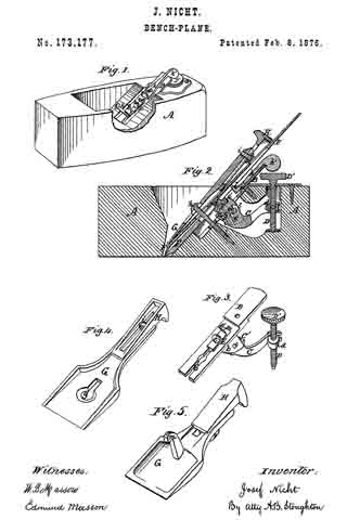
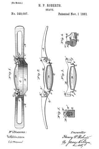
In the accompanying drawings, Figure 1 is a bottom view of a spoke or heel shave with my improvement thereon. Fig. 2 is a front view thereof. Fig. 3 is a view of the gage-roller and the frame thereof, detached. Fig. 4 is a transverse section through the middle of the roller, its supporting-frame, and the knife-blade, with its frame; and Fig. 5 is a section on line x x of Fig. 2.

The letter A represents the handle of the tool, which is curved at the center and recessed inwardly from its front edge, to receive the knife and gage-roller, the two parts of the handle being conneoted in one piece by the curved bridge B.

Immediately in front of the bridge is located the knife-blade C, curved to conform to the shape of the lower surface of the bridge, and secured to the handle by screws c. The cutting-edge of the knife is turned outwardly and projects somewhat forward of the shanks C’, by which said blade is attached to the handle.

Immediately above and partly in front of the edge of the knife is arranged a gage-roller, D, which corresponds with the shape of the knife, and in this case it tapers from its middle toward each end in such a manner that the longitudinal curve of its surface corresponds with the curve of the edge of the knife; but if it should be combined with a straight knife, it would be cylindrical in shape. This gage-roller D is mounted in an adjustable frame, E, between the downwardly-projecting lugs e, on which the roller is pivoted on screw-pivots e’. The ends E’ of the frame are provided with open slots f, through which pass screws F to secure said frame to the handle, the slots permitting either an upward or downward adjustment of the frame and roller, to bring said roller in such relation to the knife as to regulate the cut thereof as desired.

It will be observed that, owing to the curved shape of the knife, a very small portion of its edge may be brought in contact with the surface acted upon, if said surface is nearly flat, and that a heel of any of the ordinary shapes, either curved or straight, may be trimmed by the tool. The roller revolves as the tool advances, and the cut shavings coming in contact with the roller, their passage is facilitated through the opening between the roller and knife.

While the main functions of the gage-roller are to regulate the out of the knife, to remove friction and facilitate the passage of the shavings, it can be adjusted also to compensate for the wearing away of the edge of the knife. The adjustment can be made either by placing washers between the ends E’ of the roller-frame E and the frame of the blade C and removing these washers as fast as the blade wears away, or by supporting and clamping each end of the roller-frame between the heads of two screws, as shown in Figs. 1 and 5. In these figures, F’ represents the screws, inserted adjustably in the frame A. The flat head of said screws is hollow, and screw-tapped internally to receive the clamping-screws F, so that whatever may be the width of the blade C the roller D can be made to follow its edge, and the frame of said roller can be secured at each end.

I do not limit the use of my invention to heel or spoke shaves, as it is applicable to other cutting-instruments-for instance, carpenters’ planes.

Having now described my invention what I claim is —

1. The combination , with the handle, recessed as described, of the curved knife C, and the gage-roller tapered from its middle to its ends to conform to the curves of said knife, substantially as and for the purpose set forth.

2. The combination, with the recessed handle having the curved knife C secured thereto, of the roller D, arranged above said knife and mounted in an adjustable frame, E, substantially as described.

3. The combination with the handle, recessed as described, and having secured thereto the curved knife C, of the roller D, mounted in an adjustable frame, E, having the lugs e, between which the roller is pivoted, and between which the edge of the knife extends, substantially as described.

4. The combination of the centrally-curved handle, curved knife C, tapering roller D, and frame E, with adjustable hollow screws F’ and clamping-screws F, substantially as and for the purpose described.

In testimony that I claim the foregoing as my own I have hereto affixed my signature in presence of two witnesses.

HENRY P. ROBERTS.

Witnesses:
JAMES I. FOWLER,
WILLIAM K. VANDERGRIFT.

No. 231,331 – Bench-Plane (Frederic Kraengel) (1880)

[paiddownloads id=”310″]231331


UNITED STATES PATENT OFFICE.

_________________

FREDERIC KRAENGEL, OF BUFFALO, NEW YORK, ASSIGNOR OF ONE-HALF OF HIS RIGHT TO EMIL JETTER AND ALBERT JETTER, OF SAME PLACE.

BENCH-PLANE.

_________________

SPECIFICATION forming part of Letters Patent No. 231,331, dated August 17, 1880.
Application filed April 30, 1880. (No model.)

_________________

To all whom it may concern:

Be it known that I, FREDERIC KRAENGEL, of Buftalo, in the county of Erie and State of New York, have invented certain new and useful Improvements on a Bench-Plane; and I do hereby declare that the following description of my said invention, taken in connection with the accompanying sheet of drawings, forms a full, clear, and exact specification, which will enable others skilled in the art to which it appertains to make and use the same.

This invention has general reference to planes; and it consists in certain peculiar combination of parts and details of construction whereby the plane iron or irons are rendered adjustable, and the throat of the plane-stock enlarged or diminished, substantially in a manner as hereinafter first fully set forth and described, and then pointed out in the claims.

In the drawings already referred to, which serve to illustrate my said invention more fully, Figure 1 is a side elevation of a bench-plane embodying my invention. Fig. 2 is a longitudinal sectional elevation of the same. Fig. 3 is a perspective view of the plane-stock. Fig. 4. is a side elevation of a plane slightly modified. Fig. 5 is an end elevation of the same. Fig. 6 is a perspective view of the carriage, and Fig. 7 a longitudinal sectional elevation of a plane having a single plane-iron and its manner of adjustment slightly modified.

Like parts are designated by corresponding letters of reference in all the figures.

A represents the metallic plane-stock, the sides of which are raised centrally and provided with a bridge, B. In front of this bridge I provide a cross-piece, C, to which is fastened the front handle or knob, D, by means of a screw, E. In the rear of the bridge B, I provide another cross-piece, F, to which is fixed a rearwardly-projecting screw-bolt, G, and in rear of this cross-piece I provide a rise or boss, H, while near the tail of said stock I provide a lug, J.

Within the sides of the stock A, and in rear of the cross-piece F, I place a carriage, I, (shown in detail in Fig. 6,) said carriage consisting of a curved base-plate, I’, having on one end a standard, K, and on the other end a lug, L. In this standard I provide an aperture, a, for the passage of the bolt G, and in the bed-plate J’, close to the standard K, an aperture, b, for the reception of part of a nut, M, engaging said screw G. To the lug L on said carriage is fitted a handle, N.

Within the lug J, on the rear end of the stock A, I swivel a screw-rod, O, extending forwardly through the rise H and cross-piece F into a frame, l’, the forward rail, Q, of which is beveled on its upper surface to correspond somewhat to the inclination ofthe plane-irons R.

The cutting-iron has on its upper end a right-angled bend, R’, provided with a curved notch, d, into which is passed a rod, S, having on its upper end a head, S’, on its opposite end a screw-thread engaging a female thread in near the upper end of the standard K.

These plane-irons are clamped into position by a clamping-plate, T, interposed between the bridge B and said plane-irons, said clamping~plate having a micrometer-screw, U, arranged to press upon said plane-irons.

In the carriage I, I provide a slotted aperture, f, through which is passed a micrometer-screw, V, having its female thread in an aperture, g, in the lug H.

The object of constructing a plane as described is to enable me to vary the inclination of the plane-irons, and also to close or open the throat of the plane-stock by means of said irons, and these results are accomplished in the following manner:

It being desired to close or open the throat of the plane-stock, the irons are first adjusted to the thickness of shaving or cutting required. This is done by turning the head S’ of the screw-rod S in one or the opposite direction. The screw-rod S, having a fixed nut in the standard K and a swiveling connection with the plane-iron in the curved slot-hole d, Fig. 6, works the plane-iron up or down, in accordance with the direction in which it is turned, until the cutting-edge of said iron projects beyond the lower plane surface the desired distance. lf now a wider or narrower throat is wanted I first move the bearing-frame P, Fig. 3, by means of the head J’ on the screw-rod O, and the nut M on the screw-bolt G, both in the proper direction, which will cause the cutting-edge of the plane-iron to move forward or backward, as the case may be. This being accomplished, nothing remains to be done but to insert the wedge T, and then to clamp the irons down upon the standard K and rail Q by the micrometer-screw U, and finally to fix the carriage I in position by the micrometer-screw V.

To alter the inclination of the plane-irons the frame P and carriage I are moved forward or backward, as the case may be, bearing in mind the fact that the irons are, so to speak, fulcrumed upon the rail Q, and that to lower the irons the standard must be moved backward, and that a contrary movement produces a corresponding result.

It will thus be seen that the standard K and frame P form a rest for the plane-irons, and that, as already mentioned, by a forward or backward movement of the same, the size of the throat is enlarged or diminished, while by working the carriage alone the inclination of the irons is altered.

It is perfectly evident that one of the objects in view — viz., the varying of the inclination of the plane-irons — can be carried into effect without the bearing-frame P, and in Fig. 7 I have shown such a device. Here the lower or cutting edge of the plane-iron rests against the plane-stock in the throat instead of the inclined rail Q, heretofore described, while the said iron is carried upon the standard K, the same as in the other device. In this case the inclination of the plane-iron is accomplished by moving the carriage I the same as heretofore described.

By means of this device the size of the throat may also be varied to some extent by altering the inclination of the plane-iron and working the screw-rod S in a manner readily understood.

As hereinbefore described, the plane-iron is adjusted for the depth of cutting by means of the screw-rod S, Figs. 1, 2, and 7, working in the slot-hole d, Figs. 6 and 7. This construction may, however, be varied by fixing the screw-rod S as shown in Fig. 4, and allowing a circular nut, W, to operate upon said screw-rod, and with its faces within a cross-slot in the plane-iron, whereby by moving said nut up or down the screw-rod the iron is moved along in a corresponding direction.

Having thus fully described my invention, I claim as new and desire to secure by Letters Patent of the United States —

1. In bench-planes, a carriage for the bits, consisting, essentially, of the bed~plate I’, having on its forward end a standard, K, provided in its upper part with a screw-threaded aperture for the reception of an inclined screw-rod, S, said carriage having a slot-hole, f, for the passage ofa screw, V, by means of which said carriage is held down to the plane-stock, an aperture, a, in the standard K for the passage of a screw-bolt, G, and a slot-hole, b, in the bed-plate I’ for the reception of a micrometer-nut, M, whereby the said carriage is moved horizontally upon the plane-stock, substantially as and for the use and purpose specified.

2. In planes, a carriage for the plane-bits, having a standard, K, for supporting said bits, at a point about midway of their length, in combination with a bearing-frame for the lower or cutting end of said bits, said carriage and bearing-frame being both horizontally adjustable, as specified, whereby the inclination of the bit and the size of the throat of said plane may be varied simultaneously by moving the carriage and bearing-frame either in the same or in opposite directions, substantially in the manner as and for the object stated.

3. In planes, the device for adjusting the depth of cutting of the plane-iron, consisting, in combination with a fixed nut, of a revolving screw-spindle, S, operating within a slot-hole, d, in the part R’ of said plane-iron, as and for the purpose specified.

4. The combination, with the stock A, having the lug J, bridge B, and cross-piece F, with the screw-rod G, of the screw-rod O, with head J’, carriage I, with standard K, plane-iron R, with screw-rod S, and wedge T, with set-screw U, as stated.

In testimony that I claim the foregoing as my invention I have hereto set my hand in the presence of two subscribing witnesses.

F. KRAENGEL.

Witnesses:
MICHAEL J. STARK,
HATTIE L. WALKER.

No. 216,698 – Improvement In Planes (Henry B. Price) (1879)

[paiddownloads id=”304″]216698


UNITED STATES PATENT OFFICE.

_________________

HENRY B. PRICE, OF NEW YORK, N. Y.

IMPROVEMENT IN PLANES.

_________________

Specification forming part of Letters Patent No. 216,698, dated June 17, 1879; application filed April 28, 1879.

_________________

To all whom it may concern:

Be it known that I, HENRY B. PRICE, of the city of New York, in the county of New York and State of New York, have invented a new and useful Improvement in Planes, which improvement is fully set forth in the following specification, reference being had to the accompanying drawings.

The invention relates, first, to the adjustment of the angle or pitch of the cutter according to the quality of the wood to be planed; and, second, to the adjustment of the mouth of the plane; and is applicable to all kinds of planes, but especially to bench-planes composed either entirely of metal or of metal and wood combined.

Heretofore the pitch of the cutter of every plane has been fixed and unchangeable, and carpenters and joiners have been compelled to keep on hand at least two kinds of planes — one in which the cutter is at common pitch, or forty-five degrees from the horizontal line, used for soft woods, and another for hard wood, in which the cutter is either at York pitch, middle pitch, or half-pitch, corresponding, respectively, to fifty, fifty-five, and sixty degrees from the horizontal line.

The object of my invention is to provide a device by which the angle or pitch of the cutter may be altered at pleasure, so that the same plane may be used for both soft and hard wood, and by which device the mouth of the plane can also be regulated.

This object I attain as follows, reference being had to the accompanying drawings, in which —

Figure 1 represents a sectional view of the invention as applied to an ordinary metallic plane.

The wedge D, of which a sectional view is given in Fig. 2, is divided off along its inclined plane on both sides into corresponding ratchets d d d d. Half-way through the center of this wedge runs a slot, f, marked on its edges with the notches e e e e, as shown in Fig. 2.

Through the slot f passes a tap-bolt or thumb-screw, s, which screws into the sole or seat of the plane, and when screwed down holds the wedge D fast to the sole of the plane.

The tap-bolt s is provided with a gage or clamp, h, (shown in Fig. 3,) which passes over the edges of the slot f and aids in holding the wedge D in position.

When the tap-bolt s is loosened the wedge D can be slid back and forth along the slot f.

The bed-plate C, upon which the cutter B rests, is held fast by the tap-bolts i, and in the ordinary metallic plane rests directly with its heel g on the sole of the plane.

To meet the object of my invention the heel g is shortened and works in the ratchets d d d d.

The operation of the device is as follows: To obtain a higher pitch, remove the clip A and the cutter B, loosen the tap-bolts i and s, slide the wedge D forward until the heel g works into a ratchet, which shall give the required incline or angle to the bed-plate C; then fasten the tap-bolts i and s, replace the cutter B and the clip A, and the object will be attained.

To lower the pitch, go through the same process, except that the wedge D is pushed backward instead of forward.

By means of the notches e e e e e along the edges of the slot f as shown in Fig. 2, the operator, while regulating the pitch of the cutter, can at the same time adjust the mouth of the plane, so as to obtain either a “close” or a “coarse” mouth as may be desired.

By fastening the clamp or gage h (see Fig. 3) just over a notch, e, a close mouth will be obtained when the cutter is raised to the corresponding ratchet d. Thus, if the cutter is raised to a pitch represented by the fourth ratchet, then by fastening the gage h just over the fourth notch a close mouth will be obtained. A coarse mouth is procured by fastening the gage h, between any two notches — thus in the case given between the third and the fourth; that is, by moving the gage toward the third notch, but not beyond the middle point between the two, a coarse month is obtained.

The wedge D may be made of metal, wood, or any other hard substance; and in place of the tap-bolt s a thumb-screw or spring-fastening can be substituted.

What I claim as my invention is —

l. The adjustable slotted wedge D, divided along its inclined plane on both sides into corresponding ratchets, and marked with graduated notches or marks along the edges of its slot, substantially as described.

2. The combination of a wedge divided along its inclined plane on both sides into corresponding ratchets, and provided with a notched slot running half-way through its center, with a tap-bolt or screw, which passes through the slot and fastens into the sole of a plane, and which, when loosened, allows the wedge to slide back and forth along the slot, but when fastened holds the wedge firmly in position, whereby the bed of the cutter of the plane is raised or lowered and the pitch of the cutter is changed accordingly, and by which the mouth of the plane is also regulated, substantially as described.

3. In combination with the wedge D, the tap-bolt or thunmb-screws and the gage h, Substantially as described.

HENRY BRISCO PRICE.

Witnesses:
EDWARD H. H. FORDER,
RICHD. B. LYTH.

No. 199,956 – Improvement In Bench-Planes (Joseph B. Boyce) (1878)

[paiddownloads id=”288″]199956


UNITED STATES PATENT OFFICE.

_________________

JOSEPH B. BOYCE, OF LOCKPORT, NEW YORK.

IMPROVEMENT IN BENCH-PLANES.

_________________

Specification forming part of Letters Patent No. 199,956, dated February 5, 1878; application filed January 12, 1878.

_________________

To all whom it may concern:

Be it known that I, JOSEPH B. BOYCE, of Lockport, in the county of Niagara and State of New York, have invented a new and useful Improvement in Bench-Planes, which improvement is fully set forth in the following specification and accompanying drawings, in which latter —

Figure 1 is a perspective view of a common bench-plane provided with my improvement, the bits and wedge being removed in order to exhibit the improvement more fully. Fig. 2 is a vertical central longitudinal section through the plane in working condition. Fig. 3 is a perspective view of that part of the plane which I have improved.

The nature of my invention consists in certain construcinons, combinations, and arrangements of parts, hereinafter described and specifically claimed, whereby an improved adjustable metal lining for the throat and mouth of a bench-plane is produced.

The object of my invention is to protect the parts of a plane most exposed to wear by a metal lining which is of simpler construction than heretofore made, so that its application to a plane will not necessitate any material change in the construction of the plane to which it may be applied, and which may be as easily applied to an old as to a new plane.

In the drawings, A represents the body of an ordinary plane; B, the plane-iron; C, the cap-iron, with the usual coupling set-screw c and wedge D. The bed b of the plane is provided with a metal plate, E, which has an open slot, e, two oblong countersunk slots, e1, a central opening, e2, and an oblong mouth, F, which mouth F consists of abutting sides or shoulders f and a transverse connecting-strip, f’.

The plate E may be inserted from the face of the plane after the bed b of the plane has, if needs be, been reduced to receive it, and the wood at the sides and front of the mouth of the plane suitably mortised away, in order to receive the shoulders f and connectionf’, and thus the shoulders f serve as abutments for preventing the upward movement of the plate E by violent strains on the plane-iron. The plate E is fastened to the bed b of the plane by means of set-screws g, and, by means of these screws and the slots e1 e1, the readjustment of the plane-face may also be effected.

Upon the plate E the plane-iron B, with its cap C, coupled to it by the screw c, is placed, and its screw c allowed to pass into the usual recess a, which is in rear of the oblong opening e of the plate E, and, thus applied, the plane-iron and its cap are fastened with the wedge D.

The plane A is, by this construction, in a ready manner, and without material change of its throat, and at slight cost, provided with a very substantial protection of its bed and other parts liable to injury from wear.

It will be seen that while the center part of the plate E is cut away at e to admit of the passage of the large head of the set-screw c, in the usual manner, down the recess a, and at the opening e2, in order to lessen cost, still there is a continuous metal surface at either side, just opposite the wedge-abutments a’, which affords a firm bearing of the plate E upon the bed b of the plane. The plate E, above its shoulders f f is as wide as the throat or the bed of the plane, and the distance between the inner sides of the shoulders f is the same as the width of the plate E; consequently the width of the throat need not be increased in order to provide a plane with a plate, E. Besides this, any plane, new or old, may be so provided and improved without weakening the plane, by simply mortising from below, to admit the shoulders f f and connecting-strip f’. The lower end of the plate E, in conjunction with the parts f and f’, forms a lining for the mouth of the plane, and constitutes a part of the plane around its mouth, thereby protecting the plane against premature wear in and around the mouth.

I would state that the plate E may be solid at e2 without departing from my invention.

Having described my invention, what I claim as new, and desire to secure by Letters Patent, is —

1. In combination with the body and plane-iron of a carpenter’s plane, the lining-plate E, having slots e1 e1 and a longitudinal opening, e, and a mouth, F, formed with abutting shoulders f united as at f’, substantially as and for the purpose set forth.

2. A metal lining-plate, E, for a carpenter’s plane, the lower portions of which are constructed as at f, f’, and F, and the upper portion provided with a central longitudinal opening or slot, e, to correspond or register with the groove a of an ordinary plane, substantially as and for the purpose described.

Witness my hand, in the matter of my application for a patent for a bench-plane, this 8th day of January, A. D. 1878.

JOSEPH BENSON BOYCE.

Witnesses:
T. D. BABCOCK,
JAS. A. NEWTON.

No. 192,402 – Improvement In Bench-Planes (Clinton L. Adancourt) (1877)

[paiddownloads id=”280″]192402


UNITED STATES PATENT OFFICE.

_________________

CLINTON L. ADANCOURT, OF LANSINGBURG, NEW YORK.

IMPROVEMENT IN BENCH-PLANES.

_________________

Specification forming part of Letters Patent No. 192,402, dated June 26, 1877; application filed December 15, 1876.

_________________

To all whom it may concern:

Be it known that I, CLINTON L. ADANCOURT, of the town of Lansingburg, Rensselaer county and State of New York, have invented an Improvement in Bench-Planes, of which the following is a specification:

The nature of my invention consists in forming a wood-plane in adjustable sections, which may be attached to its ends, so as to increase the length of its bearing-surface when required, to vary the uses to be performed by it, and thus make one plane answer a double use by lengthening the same.

It also consists in the manner of attaching and operating the cutting bit or knife to the plane, so that the same may be used to cnt a shaving of greater or less thickness.

My invention consists of these separate features as arranged and constructed, as well as the same combined.

In the accompanying drawings, Figure 1 shows a vertical sectional view of a central section of a plane without the extension sections. Fig. 2 illustrates the same section in a top view looking down upon the plane, with the handle removed. Fig. 3 represents a vertical sectional view with the extension-sections added; and Fig. 4, a top view of the plane with extension-sections added.

Like letters designate like parts in all the figures.

The detachable handles of the plane are designated H’ H”, the cutting bit or knife B, and a hinged bank C, upon which the latter rests, and to which it is attached. The trunnions upon which the bank C is hinged to the side walls of the plane are shown at T; the cutting-edge of the bit at O; the shaving-discharge opening of the plane at S.

The cutting bit or knife is illustrated as attached to the hinged bank by means of a slotted opening in the knife, and a set-screw, as seen at I. Upon the under side of the hinged bank, and against it, so as to more it and the attached bit or knife upon the hinged apex of the former, there is shown an eccentric, e, with a handle, E. This latter is attached to the base of the plane by a screw, K. The extension-sections E’ E” are attached to the central section F by means of lapping and tenoned joints, and are secured and held in place by the set-screws S” S”, passing through the lapping and tenoned points of union, and attaching the handles of the plane.

The manner of operating the device thus formed is as follows: The cutting knife or bit B, as attached to the bank C hinged at T, is shown as in contact, upon its inner edge, with the eccentric e and its handle E, and when this handle is moved in the direction of the arrows, shown upon the eccentric at a”, the motion communicated to the bank in contact is such as to raise or depress the lower end of the bank and knife by moving the same in the direction of the arrows seen at a’ and a”. The shaving-cut will be in proportion to the dip of the bit, and this is arranged by the adjustable eccentric and handle, as it is moved around the fixed pin, the eccentric raising or depressing the cutting end of the knife.

The knife or bit, which is sharpened at both ends, may, if desired, have one end rounded, like the edge of a jack-plane knife, for coarse work, and the other with a straight cutting-edge, like a smoothing-plane, so that the knife may be reversed and used tor either kind of work, and, by the addition of the extension-section, what would serve for a jack-plane body may be changed into that of a jointer, and thus one tool maybe made to answer the purpose of several.

The body of the planes and the extension-sections may be made of either wood, iron, or other suitable material.

Having thus described my invention, what I claim, and desire to secure by Letters Patent, is —

1. In combination, the center knife or bit section F of a plane, and the extension-section E’ E”, to increase the length and base bearing-lines of the plane, as shown and described.

2. In a bench-plane, the hinged bank C, reversible cutting bit or knife B, actuating-eccentric e, and handle E, arranged to operate as described and shown.

3. In a bench-plane, the extension-sections E’ and E”, the center or bit section F, the hinged bank C, cutting bit or knife B, the adjusting-eccentric e, and handle E, arranged to operate as herein described and shown.

Signed at Troy, New York, this 12th day of December, 1876.

C. L. ADANCOURT.

Witnesses:
CHAS. M. DAVIS,
THOS. F. MURNANK.

No. 184,241 – Improvement In Plane-Guides (William H. Harris And Milo Harris) (1876)

[paiddownloads id=”271″]184241


UNITED STATES PATENT OFFICE.

_________________

WILLIAM H. HARRIS AND MILO HARRIS, OF JAMESTOWN, N. Y.

IMPROVEMENT IN PLANE-GUIDES.

_________________

Specification forming part of Letters Patent No. 184,241, dated November 14, 1876; application filed July 3, 1876.

_________________

To all whom it may concern:

Be it known that we, WM. H. HARRIS and MILO HARRIS, of Jamestown, in the county of Chautauqua and State of New York, have invented certain new and useful Improvements in Plane Guides; and we do hereby declare that the following is a full, clear, and exact description thereof, which will enable others skilled in the art to which it appertains to make and use the same, reference being had to the accompanying drawings, and to the letters of reference marked thereon, which form a part of this specification.

The object of our invention is to furnish a cheap and simple guide for bench-planes, so as to plane or saw any desired bevel; and the nature of the invention consists in the combination of devices employed, as hereinafter more fully set forth.

Figure 1 is a view of the guide, with a protractor and end plate attached to each end. Fig. 2 is a view of the metal plate attached to the end of a plane. Fig. 3 is a side view of the plane and guide, with end plate and protractor attached. Fig. 4 is a view of our invention as applied to a saw-table.

ln the drawings, A represents a semicircular bevel-protractor, made of suitable metal, and having a long circular slot near its center, through which the bolt or screw D passes to secure it firmly to the end plate B, and also a semicircular stud, x, at its lower edge, that turns in the semicircular indentures c c c, and also a lip turned at right angles with its surface, through which screws pass to securely fasten it to the guide C. B is a metal plate, that is securely fastened to the end of a plane, as shown in Fig. 2, and having screw-holes for this purpose, and holes a a a, with a screw-thread cut in them to receive the bolt D. It has also sernicircular indentures c c c in its lower edge to receive the stud x of the bevel-protractor. One of these plates, with the bevel-protractor, is fastened at each end of the plane, and, having the guide C attached, is shown in Figs. 1 and 2. The object of having so many places for the bolt D is that by so doing we can use any part of the face of the plane, and by changing ends with the guide C it will work on the back part of the plane-face, thus enabling us to bevel either edge of the board. The object of indentures c c c and stud x is to form a center for the bevel-protractor to turn on, in order that the corner of the guide C will always retain its relative position with the face of the plane, and as the bolt-holes a a a are placed at an angle of forty-five degrees with the indentures c c c we do not have to use but three indentures c c c for all the bolt-holes, no matter on which side of the plane-face the gage is used.

The plate B may be made with a long slot through its center, and a movable nut to receive the bolt D, or said plate may be made dovetailing, and inserted in a movable plate on which the bevel-protractor moves across the plane; but we prefer the manner shown in the drawings, as it is cheaper and more secure.

By means of the semicircular stud x in the bevel protractor A, and the indentures c c c in the metal plate B, the guide C can be moved to any part of the face of the plane, and the inner corner of said guideis held in the exact center of the circle described by the bevel-protractor A, and the guide is kept close to the face of the plane at any angle it maybe turned without any further adjustment, and by turning the lip d parallel with the face of the plane a much thinner guide can be used and thinner lumber planed without coming in contact with the work-bench.

We claim —

The combination of the bevel-protractor A, having stud x and lip d, with the end plate B, provided with the semicircular indentations c c c, the screw-bolt D, and the guide C, all constructed to operate as shown and described, and for the purpose specified.

In testimony that we claim the foregoing as our own invention we affix our signatures in presence of two witnesses.

WM. H. HARRIS.
MILO HARRIS.

Witnesses:
J. E. GOULD,
J. E. HARRIS.

No. 179,494 – Improvement In Bench-Planes (John J. Tower) (1876)

[paiddownloads id=”264″]179494


UNITED STATES PATENT OFFICE.

_________________

JOHN J. TOWER, OF BROOKLYN, NEW YORK.

IMPROVEMENT IN BENCH-PLANES.

_________________

Specification forming part of Letters Patent No. 179,494, dated July 4, 1876; application filed May 29, 1876.

_________________

To all whom it may concern:

Be it known that I, JOHN J. TOWER, of Brooklyn, in the county of Kings and State of New York, have invented an Improvement in Metal Plane-Handles, of which the following is a specification:

Metal planes have heretofore been constructed with handles of wood, and also with globular knobs at the forward end of the plane.

My improvement relates to a hollow cast-metal handle, secured to the plane by dove-tailed projections, so that the connection is very strong and durable, and at the same time the handle is very light, and of a size and shape to be grasped by the hand.

The handle is represented in the drawing by a vertical seetion, Figure 1, horizontal section, Fig. 2, and cross-section, Fig. 3.

The handle a is of cast metal, preferably of iron. It is made hollow, so as to be as light as possible and maintain the requisite strength. The general shape of this handle is similar to those made of wood, and hence it is as convenient in use. In order to strengthen the lower part of the handle, and prevent the same being bent by the attachment to the plate b of the plane, I introduce the cross-bar c, cast with the rest of the handle. Dovetails that taper slightly are employed for fastening the base of the handle to the plane-stock. These dovetails are made by lips inside the base of the handle, as seen at e. The dove-tail block f upon the plane-stock b is shorter than the base of the plane-handle a, and the dovetail portions e do not extend the whole distance along the inner edges of the handle, so that the handle a can be put over the dove-tail-block f by slipping it from the back forward, and keeping the back edge down, in order that the handle may receive the dove-tail-block, and the parts tapering, the handle may be secured firmly by driving it forward upon the dovetail block. By this construction it is not necessary to have any opening at the forward part of the base of the handle, as such base sets down flat upon the plane-stock, and makes a neat, handsome, and durable connection, the dovetail not being visible.

This hollow cast-iron plane-handle may be plated or otherwise finished, and as the handle extends to the upper surface of the bottom of the plane, the hand of the operator can be as near to the surface of the wood as possible, so that the power can be exerted to good advantage.

I do not claim a plane with a hollow knob or handle with dovetail projections for holding the plane-iron to the stock, as this has been used; neither do I claim a hollow metal plane-handle.

I claim as my invention —

The metallic plane-handle cast hollow, with a cross-bar, c, and dovetail lips e extending a part of the distance along the inner portion of the base, in combination with the dovetail block f upon the stock of the plane, substantially as set forth.

Signed by me this 22d day of May, A. D. 1876.

JOHN J. TOWER.

Witnesses:
GEO. T. PINCKNEY,
CHAS. H. SMITH.

No. 174,870 – Improvement In Carpenters’ Planes (Elliot G. Storke) (1876)

[paiddownloads id=”259″]174870


UNITED STATES PATENT OFFICE.

_________________

ELLIOT G. STORKE, OF AUBURN, NEW YORK.

IMPROVEMENT IN CARPENTERS’ PLANES.

_________________

Specification forming part of Letters Patent No. 174,870, dated March 14, 1876; application filed February 7, 1876.

_________________

To all whom it may concern:

Be it known that I, ELLIOT G. STORKE, of Auburn, in the State of New York, have invented certain new and useful Improvements in Carpenters’ Planes, of which the following is a specification:

The object of my invention is to provide a simple, easy, and exact method of adjusting the bits or cutters of carpenters’ planes.

Figure 1 is a longitudinal vertical central section of an ordinary metallic plane embodying my improvements. Fig. 2 is a perspective view of the same with the bit removed.

Similar letters refer to the same parts in the respective figures.

A is the bed-plate for the support of the bit. Near the transverse center thereof is placed the sliding plate B, running in ways cut in the said bed-plate, having in its upper face an oval recess, C, for the reception of the cap screw heads of double plane-irons. From the lower face of the said sliding plate projects the shank-nut D, so far below the bed-plate that when the screw E is passed through its lower end, on a line parallel with the pitch of the plane-iron, a large thumb-wheel, F, can be mounted upon the upper end thereof without colliding with the plane-iron above or the plane-body below. That thumb-wheel is supplied with six arms, H, equally spaced upon its hub, giving as many distinct and conveniently-located levers, by which the workman can easily revolve the said wheel and move the parts with which it is connected. From the lower face of the bed-plate A, and near its upper end, projects the shank-bearing for the adjusting-screw G, of the same length as the shank-nut D, and in line therewith. Through the lower end of the said shank-bearing passes the upper end of the screw E into the hub of the said thumb-wheel, the former being shouldered where it joins the inner face of the latter, and the wheel, being pinned to the screw, carries the latter with it. Now, by revolving the thumb-wheel in the shank-bearing G, the shank-nut D and the sliding plate B are raised or lowered at pleasure, giving to the cutters a corresponding movement, and securing any desired thickness of shaving.

It will be seen from the foregoing description that my invention consists, mainly, in devices by which plane-bits are adjusted by a single direct-acting screw, operating through the medium of the cap-plates of double irons. The two shanks or lugs D and G, the screw E and sliding plate B, and the thumb-wheel F, with its arms H, are the devices employed for this purpose.

By projecting those lugs far below the bed-plate A — that is to say, far enough to carry the axis of the thumb-wheel to the center, or thereabout, of the space between the plane-iron and plane-body — I am enabled to use upon the screw E a large thumb-wheel supplied with the lever-arms H, and I thus gain all the power necessary to move the bits easily by the single screw E. The arms H, lying both to the right and left of the plane-handle, are easily and conveniently operated by the workman, either by the thumb from the left, or the fingers from the right, or both conjointly, without removing the hand — a device possessing decided conveniences over the circular thumb-screw heads heretofore in use for the same purpose.

I am aware that screws have been applied directly to plane-irons for their adjustment, but not in that way to the cap-plates of double irons, nor to their screw-heads. In the latter application the maximum movement of the operating-screw is less than one-half inch, in the former fully two and one-half inches, and a special attachment must be made to the cutter in which to work the screw; but that application, so far as I am informed, has been abandoned for the lack of power to operate the bits, and in its stead various combinations of single levers, or levers and cams operated by screws, have been resorted to, the objection to which is the increased cost of construction, and the greater liability to derangements and backlash.

I am also aware that various devices for adjusting plane-bits have been applied to the cap-plates or cap-screw heads of double plane-irons, but none, it is believed, in which that adjustment has been effected by a single screw without other intermediate devices.

The simplicity, durability, and practical efficiency of the devices herein described will, it is believed, be clearly apparent, as well as their superiority to those hitherto employed for the same purpose.

Having described my invention, I shall state my claim as follows:

The direct-acting or adjusting screw, having a thumb-wheel formed with lever-arms, as described, in combination with the bed-plate, having an elongated shank-bearing, and the sliding socket-plate, having an elongated shank-nut, all substantially as and for the purposes shown and set forth.

In testimony whereof I have hereunto signed my name this 3d day of February, A. D. 1876.

ELLIOT G. STORKE.

Witnesses:
H. L. STORKE,
LEWIS L. SMITH.

No. 174,399 – Improvement In Spoke-Shaves (Albert A. Wood) (1876)

[paiddownloads id=”258″]174399


UNITED STATES PATENT OFFICE.

_________________

ALBERT A. WOOD, OF MANLIUS, NEW YORK.

IMPROVEMENT IN SPOKE-SHAVES.

_________________

Specification forming part of Letters Patent No. 174,399, dated March 7, 1876; application filed July 31, 1875.

_________________

To all whom it may concern:

Be it known that I, ALBERT A. WOOD, of Manlius, in the county of Onondaga and State of New York, have invented a new and useful Improvement in Spoke-Shaves; and I hereby declare the following to be such a full, clear, and exact description of the same as will enable others skilled in the art to which it pertains to construct the same, reference being had to the accompanying drawings, making a part of this specification, and to the letters of reference marked thereon, similar letters indicating corresponding parts in the different figures.

This invention relates to that class of spoke-shaves commonly used by wheelwrights and joiners, the object being to provide a ready means of adjustment for the cutting-bit, so as to enable it to take a cut of a different thickness without being released from its holding-screws and readjusted; and the invention consists in attaching the cutting-bit to an oscillating plate, which is adjusted by means of a thumb-screw and spring, as will be hereinafter fully set forth, and then specifically pointed out in the claim.

Figure 1 of the drawings is a perspective view of the device complete. Fig. 2 shows the throat of the shave with the bit and its carrying-plate removed. Fig. 3 represents the carrying-plate with grooves and recess for the reception of the spring.

The handle or stock A of the shave is made of metal, and is provided with a throat, B, for the reception of the cutting-bit. Within this throat are two longitudinal projections or ridges, a a, and a third elevation, b, upon which the springs g rests. The plate C, having two depressions, d d, at each side, rests upon the projections a a of the stock, within the throat, upon which it oscillates. It also has secured to it, by the screws e e, a cutting-bit, D. This plate is further provided with a recess, f in which is placed a spring, g, the whole of these parts being retained in their proper positions within the throat of the stock by a thumb-screw, h, which passes through the plate and into the stock.

In operating this tool, the plate C, having the spring g in its proper recess, may be placed within the throat of the stock, and the thumb-screw h inserted, and turned up until the plate finds a bearing upon the stock; the bit D is then placed in position, and secured to the plate G by the screws e e, it being so adjusted that its cutting-edge shall project slightly through the throat, so as to take the thinnest shaving which may at any time be required. In order to increase the bite of the tool, and cause it to cut thicker shavings, it is only necessary to turn the thumb-screw slightly backward, which will allow the spring to throw up the outer end of the plate, which, oscillating upon the projections a a, causes the bit to project to a greater distance from the face of the stock, and consequently to cut a shaving of greater thickness, thus avoiding the necessity of loosening and refastening the cutting-bit at each adjustment thereof.

Having thus described my invention, I claim as new, and desire to secure by Letters Patent, the following:

The adjusting-plate C, provided with the recess f and carrying the cutting-bit D, in combination with the stock A and spring g, substantially as and for the purpose specified.

In testimony that I claim the foregoing I have hereunto affixed my signature this 30th day of July, 1875.

ALBERT A. WOOD. [L. S.]

Witnesses:
N. E. ROBINSON,
GEORGE S. BALLOCH.

No. 173,984 – Improvement In Bench-Planes (George F. Mortensen) (1876)

[paiddownloads id=”257″]173984


UNITED STATES PATENT OFFICE.

_________________

GEORGE F. MORTENSEN, OF NEW YORK, N. Y.

IMPROVEMENT IN BENCH-PLANES.

_________________

Specification forming part of Letters Patent No. 173,984, dated February 22, 1876; application filed August 20, 1875.

_________________

To all whom it may concern:

Be it known that I, GEORGE F. MORTENSEN, of the city, county, and State of New York, have invented a new and useful lmprovement in Bench-Planes, which improvement is fully set forth in the following specification, reference being had to the accompanying drawing, in which —

Figure 1 represents a longitudinal section of my improvement. Fig. 2 is a reverse plan view thereof, partly in section. Fig. 3 is a view of the slotted cap.

Similar letters indicate corresponding parts.

My invention relates to improvements in bench-planes, and as to one of its features particularly — to planes whose “stock” is made of wood.

That part of my invention relating to wooden planes consists in combining, with the “sole” thereof, an adjustable shoe for the purpose of regulating the “mouth” containing the plane-iron, the said shoe being made adjustable both vertically and horizontally through the medium of set-screws and of slots, through which the screws pass.

In the drawing, the letter A designates the stock of my plane, and B is the sole. C is the adjustable shoe, which is preferably made of metal, and is let into a cavity, D, immediately in front of the mouth a. The said shoe C is subjected to the action of set-screws E, which extend vertically into or through the stock A, to which end the stock is provided with a protecting-plate, F. The set-screws E extend both in an upward or downward direction. When the set-screws extend in both directions, as shown in Fig. 1, the head of the single screw, in this example extending downward, is preferably concealed in a socket, G, while, in order to conceal the heads of the upwardly-extending screws, and to impart to the shoe C a smooth surface, a face-plate, H, is affixed to the shoe. This face-plate is removed in Fig. 2, in order to expose the set-screws.

The set-screws pass through slots b, which, in the example shown in Fig. 1, are formed in the shoe C; but, if desired, the slots may be formed in the protecting-plate F.

By means of the set-screws E I am enabled to adjust the shoe C vertically toward the cavity D, for the purpose of preserving its level with the sole B, when the latter is “corrected,” while by providing the sole or the protecting-plate F with slots b, and passing the set-screws through the slots, the shoe may be adjusted to different positions horizontally, and particularly with respect to the mouth at, which, as is well known, becomes enlarged when the plane is corrected, owing to the slope of the bed d of the plane-iron.

The plane-iron I is made of the usual form, with an upper and a lower section, connected together by a screw, J.

K designates a cap, which, together with an eccentric or cam lever, L, constitutes a clamp for fixing the plane-iron on the bed d. The cap K is provided with a slot, N, which has at one end a hole, O, (see Fig. 3,) equal in diameter to that of a stud, P, formed by the head of a screw, which is fastened to the bed d, so that by moving the cap K to such a position that the stud occupies the narrow part of the slot, the cap is rendered capable of tilting under the stud P.

The cam-lever L turns on a pivot, c, and is fastened on the upper end of the cap K.

When the cam-lever is turned to the position shown in the drawing, it bears on the upper portion of the top section of the plane-iron I, thereby raising the upper end of the cap K, while by the tilting of the cap thus occasioned its lower end is caused to bear on the corresponding portion of said top section of the plane-iron, and by this arrangement the iron may be readily adjusted and firmly held in any position.

The stock A of my plane is made in two divisions, Q, (or more than two, if required,)
which are connected together by side strips or cheeks R. By this construction of the stock, far greater strength is imparted to it than when made in a single piece, while the parts of the stock, moreover, being very readily put together, the whole can be furnished at a comparitively small cost.

What I claim as new, end desire to secure by Letters Patent, is —

The combination, with the stock of a bench-plane, of a, recessed shoe, C, with a, detachable face-plate, H, the set-screws E E E and slots b, all constructed to operate substantially as described.

In testimony that I claim the foregoing I have hereunto set my hand and seal this 17th day of August, 1875.

GEORGE F. MORTENSEN. [L. S.]

Witnesses:
E. F. KASTENHUBER,
FRANCIS FORBES.

No. 173,177 – Improvement In Bench-Planes (Josef Nicht) (1876)

[paiddownloads id=”256″]173177


UNITED STATES PATENT OFFICE.

_________________

JOSEF NICHT, OF AUBURN, NEW YORK.

IMPROVEMENT IN BENCH-PLANES.

_________________

Specification forming part of Letters Patent No. 173,177, dated February 8, 1876; application filed July 29, 1875.

_________________

To all whom it may concern:

Be it known that I, JOSEF NICHT, of Auburn, in the county of Cayuga and State of New York, have invented certain new and useful Improvements in Bench-Planes; and that the following is a full, clear, and exact description of the same, reference being had to the accompanying drawings making a part of this specification, in which —

Figure 1 represents a perspective view of my improved plane, with the plane-irons and fastening-cap removed. Fig. 2 represents a longitudinal vertical section through my improved plane. Fig. 3 represents a detached view of the mechanism employed for raising or lowering the plane-irons. Fig. 4 represents a perspective view ofthe cap overlying the plane-irons, showing its under side and connected wedge. Fig. 5 represents a modification of the same.

Similar letters of reference, where they occur, denote like parts in all the figures.

My invention relates to certain combinations of mechanisms used to set or adjust plane-irons from the exterior of the plane without separating the parts, and with great expedition and accuracy.

My invention relates also to the means by which the plane-irons can be moved laterally to adjust them in that direction, and also to the means by which the plane-irons are retained in position by means of a cap and wedge.

To enable others skilled in the art to make and use my invention, I will proceed to describe the same with reference to the drawings.

A represents the wooden stock of a plane, to which is attached, by means of the screw a, the plate B, that has formed on its under side bearings b for the shaft c, around which the geared segment and lever C revolve. The rear end of this lever C is slotted, so as to fit over a pin formed on one side of the nut d, that is raised or lowered by a screw-shaft, D, having a knob or thumb-piece, D’, upon its upper end, by which it may be readily operated to raise or lower the nut d, and correspondingly the rear end of the lever C. On the front of the lever C there is a geared segment, C’, that engages with the rack E. This rack is located in a groove, b’, cut out of the plate B, so as to furnish it with the bearings required for a free and steady motion up or down. This rack E has on its upper surface a central projection, e, and another at e’, either or both of which engage with the head of a screw, f that is centrally recessed for that purpose. This screw f is otherwise the one employed to connect the plane-iron F and its iron cap F’, so that by turning the screw-shaft D the plane-irons may be moved up or down at pleasure to adjust them, and when adjusted they are firmly held in that position. G is a metallic cap overlying the plane-irons. A slot, g, is cut through it, so as to allow the head of the screw h to pass through it and rest on its upper surface. Under the rear of this cap G there is a wedge, H, by which the cap may be raised at that point and pressed against the plane-irons at or near their lower ends to clamp them together. The wedge H is retained in connection with the cap G by grooves formed on the latter, and a bolt, i, that connects the two together. To the plate B and stock A is pivoted at a a lever, k, the rear end of which projects upward, so as to be readily operated from the exterior of the plane, it terminating in a knob, k’, by which it can be moved. The inner end of this lever k is bent up, as at l, and passes into the slot ordinarily cut in plane-irons F, so that the latter can be moved laterally to adjust said irons in that direction. Thus the vertical and lateral adjustments of the plane-irons may be instantly and very accurately made.

In Fig. 5 is shown a modification of the cap G, the slot g of Fig. 4 being dispensed with, and the hook m formed in its place, so as to engage under the head of a bolt, or any similar projection attached to the stock A of the plane.

I claim as my invention —

In combination with the plane-stock A, the longitudinally-slotted plane-iron F and the mechanism composed of the screw h and cap G, carrying, secured to it, the wedge H, for clamping said plane-iron to the plane, the lever k’, pivoted to the stock of the plane, and engaging with the slot of the plane-iron to adjust it laterally, all arranged substantially as shown and described.

JOSEF NICHT.

Witnesses:
HORACE T. COOK,
W. P. BEARDSLEY.

No. 148,649 – Improvement In Metallic Bench-Planes (John A. Baines) (1874)

[paiddownloads id=”227″]148649


UNITED STATES PATENT OFFICE.

_________________

JOHN A. BAINES, OF NEW YORK, N. Y.

IMPROVEMENT IN METALLIC BENCH-PLANES.

_________________

Specification forming part of Letters Patent No. 148,649, dated March 17, 1874; application filed February 9, 1874.

_________________

To all whom it may concern:

Be it known that I, JOHN A. BAINES, of New York city, in the county of New York and in the State of New York, have invented certain new and useful Improvements in Metallic Bench-Planes; and do hereby declare that the following is a full, clear, and exact description thereof, reference being had to the accompanying drawings making a part of this specification, in which —

Figure 1 is a perspective view of the main frame, side gage, and sole or base plates of my plane. Fig. 2 is a plan view of the lower side of said frame. Fig. 3 is a perspective view of the detachable block or frame used for forming the smoothing and filletster planes. Fig. 4 is a plan view of the lower side of the same. Fig. 5 is a perspective view of the bottom gage. Fig. 6 is a like view of the detachable block employed for forming the sash-plane. Fig. 7 is a perspective view of the smoothing-plane complete. Fig. 8 is a plan view of the lower side of the same. Fig. 9 is a vertical section upon line x x of Fig. 8. Fig. 10 is a side elevation of the filletster-plane. Fig. 11 is a plan view of the lower side of the same. Fig. 12 is a plan view of the lower side of the tonguing-plane. Figs. 13 and 14 are, respectively, side and front elevations of the same. Fig. 15 is a plan view of the lower side of the grooving-plane. Figs. 16 and 17 are, respectively, a front and a side elevation of said plane. Fig. 18 is a plan view of the lower side of the sash-plane. Fig. 19 is a front elevation of the same. Fig. 20 is a section of said plane on line z z of Fig. 18, the cutting-tools being arranged for forming the meeting rail. Fig. 21 is a plan view of the lower side of a bead or round plane. Figs. 22 and 23 are, respectively, a side and a front elevation of the same. Fig. 24. is a front elevation of a hollow plane. Fig. 25 is a perspective view of a plow-plane. Fig. 26 is a plan view of the lower side of the same. Fig. 27 is a like view of a plane for forming center-beads. Fig. 23 is a front elevation of the same; and Fig. 29 is a side view of the cutting-irons employed, showing the shape of the cutting-edge of the same.

Letters of like name and kind refer to like parts in each of the figures.

The design of my invention is to lessen the cost and reduce the bulk of planes for producing irregular work; and to this end it consists in the construction and combination of the frame and various attachments employed for forming the different styles of plane, substantially as and for the purpose hereinafter specified.

In the annexed drawings, A represents the main frame of my tool, which has a plain lower surface, and at its upper side has such conformation as to enable it to receive the usual form of cutting-irons with the fastening-wedge, to permit the upward passage of shavings, and to provide for the attachment of a handle, B. Within the lower side, and near one edge of the frame A, is formed a narrow groove, C, which extends vertically upward within an enlargement or rib, A’, provided for the purpose, has a line parallel to the side of said frame, and receives two plates, D and D’, (shown in Fig. 1,) that form the base or sole. Two or more removable pins, d and d, pass horizontally and laterally inward through the side of said frame A, and through each of said plates D and D’, and locks the latter securely in position, when desired. Upon the inner side of the name A is formed a vertical groove, a, that receives the standard e of an adjustable gage, E, which gage is secured to or upon said frame, and held in vertical position by means of a screw, F, that passes into a threaded opening in the latter through a vertical slot in said standard.

Within the upper side of the frame A, near its ends, are formed two transverse grooves, g and g, that receive the ends of two corresponding bars, G and G’, which bars, when in position, are fastened by means of a screw, H, as shown in the front bar, or a pin, H’, as seen in the rear bar, said screw or pin being passed vertically downward through said bars into said frame. From the frame A the bars G and G’ extend laterally outward, and have their lower sides upon a line with the lower face of the former, in which position they form an extension of said face, and permit of the attachment of an angle-plate, I, (shown in Fig. 5,) which plate, being adjustable laterally toward or from the cutting-irons, forms a gage for several forms of plane. Within the lower side of the frame A, at or near its longitudinal center, is formed a transverse slot, a’; in rear of the same is provided a longitudinal slot, a”; while in front of the throat A” is a second longitudinal slot, a”’, the object of which is to enable the attachment of various parts required for forming several of the planes, said parts being described in connection with each plane of which it forms a part.

For use as a smoothing-plane, a hollow block, K, having the general form shown in Fig. 3, is placed upon the lower side of the main frame, and secured in posiuon by means of its inner side k, which extends upward into the groove C, and is provided with suitable openings k’ for the passage of the pins d and d.

The bolt k” of an adjustable throat-piece, k”’, projects upward through slots in said block and main frame and furnishes an additional means for securing said parts together.

The block K is provided with a throat, k””, which coincides with the throat of the main frame, and enables a cutting-iron, of usual form to be inserted and secured in place by means of the ordinary wedge.

To construct a filletster, the inner end of the throat k”” of the block K is uncovered by the removal of a covering plate or cap, K’, and the gage I attached to the lower face and outer side of said block, suitable threaded openings k””’ being provided within said block, for the reception of the binding-screws I’ of said gage.

The gage E is also placed in position and adjusted to depth, and, in connection with said gage I, enables the dimensions of the fillet or rabbet to be determined with certainty.

For use as a tonguing (matching) plane, the plates D and D’ are placed in position, the gage I attached to the lower face of the frame A, and upon the face of said gage is attached two blocks, L and L’, which have the form shown in Fig. 5, and perform the double office of a support for the heel of the inner half of the cutting-iron, and a gage for the depth of its cut. The gage E is also em-
ployed, its office being to insure the correct depth of cut for the outer half of said cutting-iron.

For a grooving-plane, the blocks L and L’ are removed, the gage I is moved inward to the position required by the thickness of the board, and a single cutting-tool inserted in place of the double one before used. The gage E is now reversed, so as to cause its bearing-face to extend inward nearly to the cutting-iron, the arrangement of parts being as shown in Figs. 15 and 16.

For use as a sash-plane, the plates D and D’ and the gages E and I are removed, and a block, M, having the form shown in Figs. 6 and 20, secured upon the lower side of the frame A by means of a screw, m, which extends upward through the longitudinal slot a” in said frame, and a second screw, m’, that passes downward through the transverse slot a”’ near the front end of said frame, and has its threaded end contained within a corresponding opening provided in said block. The blocks L and L’ are now attached to the inner face of the block M, where they serve as supports and gages for the cutting-iron that forms within the sash-rail the rabbet for containing glass, while the cutter for forming the molding upon said sash-rail is placed within a suitable throat formed in and through the molded face of said block M.

For use in forming the meeting rail, the gage-blocks L and L’ are removed, and the cutter shown in Fig. 20 inserted in place of that before employed for forming the glass rabbet.

For use as a beading or rounding plane, the block M is removed and a block, N, having the transverse shape shown in Fig. 23, is secured in its place upon the frame A, the size and shape of the groove it within the lower face of said blocks N and the corresponding features of the cutting-iron being varied to suit the especial purpose for which the tool is required.

To form a hollow plane, the shape of the lower face of the block N and of the edge of the cutting-iron are reversed, as shown in Fig. 24.

For use as a plow, the plates D and D’ are placed within the groove C, and the adjustable gage I secured upon the lower face of the frame A, or upon the extension–bars G and G’, after which the usual form of cutting-iron is inserted within the space between said plates, its heel resting upon the forward end of the rear plate D.

To form a center-bead plane, the extension-bars G and G’ and gage I are employed as before, the plates D and D’ are removed, and a hollow block, O, having the transverse form shown in Fig. 28, secured upon the lower face of the frame A. A cutting-iron having its lower or cutting end formed upon a line which corresponds to the grooved face of said block is placed in position within the throat o of the same, after which the plane is used in the ordinary manner.

As seen in Fig. 29, the lower end and forward side of such plane-irons as usually require caps are beveled off at an angle of about forty-five degrees with said side, so as to render more obtuse the angle of the cutting-edge, and enable any kind of wood to be cut smoothly and with ease without the use of a cap, by which means a saving is effected in the cost of said cutting-irons, and in the time and labor required in manipulating the planes.

The device thus constructed combines, in a simple and compact form, a number of tools which are usually separate, and enables them to be furnished at a comparatively small cost.

Having thus fully set forth the nature and merits of my invention, what I claim as new is —

The hereinbefore-described plane, constructed in the manner and for the purpose substantially as specified.

In testimony that I claim the foregoing, I have hereunto set my hand this 6th day of February, 1874.

JOHN A. BAINES.

Witnesses:
JOHN R. YOUNG,
JAS. E. HUTCHINSON.

No. 161,609 – Improvement In Bench-Planes (Thomas Hagerty) (1875)

[paiddownloads id=”241″]161609


UNITED STATES PATENT OFFICE.

_________________

THOMAS HAGERTY, OF NEW YORK, N. Y., ASSIGNOR TO JOHN ALFRED PICKERSGILL, OF SAME PLACE.

IMPROVEMENT IN BENCH-PLANES.

_________________

Specification forming part of Letters Patent No. 161,609, dated April 6 , 1875; application filed December 2, 1874.

_________________

To all whom it may concern:

Be it known that I, THOMAS HAGERTY, of the city, county, and State of New York, have invented certain Improvements in Bench-Planes; and I declare the following to be a full, clear, and exact description thereof, reference being had to the accompanying drawing, in which the figure is a view of my improvement, the side of the plane-stock being broken away, so as to show the construction of the several parts as they appear in the stock.

The object of my invention is to improve the construction of bench-planes, so that the bit may be conveniently placed out of the way of the hand, held firmly on its bed, and the cutting-edge of the plane-iron be more readily adjusted with reference to the bottom surface of the plane-stock. To this end the invention consists in the combination and arrangement of the devices employed, all as hereinafter described.

In the drawing, A is the plane-stock, made to receive a semicircular bed-block, B. The bed-block rests on projections cast on the bottom of the plane-stock, and is secured to it by screws a a, which pass through oblong holes, which are intended for adjusting the mouth of the stock. C is the plane-iron, bent to conform to the same circle as the bed-block, and is provided with a cap, D, bent to conform to the plane-iron, and secured to it by a clamp-screw, b. The cap iron is slotted crossvvise at its upper end to receive the flange of the adjusting-nut E, and a hole is made through it in front of the clamp-screw b to receive the screw a2, which secures the top clamp F, cap D, and plane-iron C to bed-block B. The clamp F is of a smaller circle than the plane-iron, so that both ends rest on the cap and hold the parts firmly to the bed-block. The adjusting-nut E traverses a male screw, b’, which is set on an incline, so that the flange enters the notch in the cap-iron, and is also provided with a slot in front for applying a screwdriver to operate the bit. The same construction of bit may be applied to scraper-plane by raising the semicircular bed-block to the proper height, and making the bit so as to conform to its circle.

Having thus described my invention, what I claim as new, and desire to secure by Letters Patent, is —

The combination of the plane-stock A with the bed-block B, semicircular bit C, cap D, and adjusting-nut E, provided with screw b, all constructed and operating substantially as herein shown and described.

THOMAS HAGERTY.

Witnesses:
W. G. TUCK,
WM. RUTHERFORD.

No. 162,710 – Improvement In Carpenters’ Planes (Elliot G. Storke) (1875)

[paiddownloads id=”243″]162710


UNITED STATES PATENT OFFICE.

_________________

ELLIOT G. STORKE, OF AUBURN, NEW YORK.

IMPROVEMENT IN CARPENTERS’ PLANES.

_________________

Specification forming part of Letters Patent No. 162,710, dated April 27, 1875; application filed January 6, 1875.

_________________

To all whom it may concern:

Be it known that I, ELLIOT G. STORKE, of Auburn, New York, have invented certain new and useful Improvements in Carpenters’ Planes, of which the following is a specification:

My improvements relate to setting and fastening the bits of planes, and also to means for giving to bench-planes a metallic and adjustable throat-piece.

The nature of my invention can best be explained by reference to the accompanying drawings, in which —

Figure 1 is a longitudinal vertical central section of a plane embodying my improvements. Fig. 2 is a perspective view of the same with the plane-iron fastener and bit removed. Fig. 3, 4, 5, are views of detached parts hereinafter described. The plane represented is one with a metal top and wooden face.

A is the lever by which the bit is set or adjusted to cut fine or coarse shavings, and Y its upward-projecting point; B, the standards which support the upper end of the bit B’; C, the journals of the said lever A, said journals resting in bearings cut in projections on the front of standards B, in which bearings the journals have a lateral or end-wise play. L L are two grooves cut on the interior opposite sides of the frame or plane-body, for the reception of lugs D’ of the plane-iron fastener D, shown in perspective in Fig. 3. The lugs are on the sides of the fastener and near its longitudinal center, and at its rear end is the thumb-screw. F is the cap and G the screw of an ordinary plane-iron, the screw-head being countersunk at at to receive the globular point Y of the lever A. s is a blank screw-hole tapped in the cap, into which the said cap-screw can be removed when it becomes necessary, by the wearing away of the wooden face of the plane, if such be used, to raise the cutting-iron.

The devices thus far described for fastening and setting the bit are operated as follows: The lever A is placed in its bearings in the standards B; the cap is screwed in the usual way upon an ordinary plane-iron, and the recess in the screw-head laid upon the point Y. When so laid the bit is upon its bearings, and the point Y fits neatly the recess a in the cap. The lugs D’ of the fastener are now placed in the grooves L L and the thumb-screw E tightened, which binds the bits to its bearings with more or less firmness, according to the pressure given by the screw.

The lugs D’ of the plane-iron fastener are introduced into the inclined grooves L L at the lower and open ends of the latter. The upper ends of said grooves are shouldered or closed, as seen in the drawing. The thick heel of the plane-iron, when drawn back, tends to force the fastener upward. This movement in time has the effect of smoothing the surfaces of contact of the lugs and grooves, thus increasing the liability of the fastener to work upward in the grooves. To remedy this difficulty l shoulder or close the grooves at their upper ends, as shown, thus preventing liability of the fastener becoming disengaged from the grooves. The long arm of the lever A is immediately under and within easy reach of the fingers of the workman, while grasping the plane-handle, and by raising or lowering it the adjustments of the bits are quickly and easily made, under the firmest pressure of the screw. I so construct the lever with a central hub bearing accurately-turned journals at its ends, with the spherical point Y rising upward from its center, and from which extends the long arm toward the plane-handle, that all its parts, being in one piece, are wrought with much greater facility, accuracy, and economy, and placed and maintained in position more easily and firmly than if separate pieces were employed in its construction, and so also that its journals have a free and accurate lateral or sidewise movement, by which the upper end of the bit, when fastened, can be so pushed to right or left as to square its cutting-edge with the face of the plane. By connecting the spherical point Y with the screw-heads of double plane-irons, I obtain not only a very cheap, but a very efficient means of adjusting them, for these screw-heads always maintain, practically, the same position, relatively to the cutting-edge of the bit, and can be countersunk at a merely nominal cost. The sweep of the long arm of the lever A carries the point Y through a sufficient arc to give the required adjustment to the bit, and a leverage of such power that the adjustment is easily made.

As this device for fastening and setting the bits of planes can be applied with equal facility to metallic planes, and to those having metallic tops and wooden faces, I provide for the wearing away of the latter by tapping the said cap a second time at s, into which, as the face of the plane wears away, the said screw can be removed, and in that way the bit can be worked higher up.

The metallic and adjustable section or throat-piece is shown detached in Fig. 5. I is the flat surface thereof, accurately milled on its sides to fit ways or guides out on each of the inner sides of the said frames or plane-body, on its upper face and immediately forward of the bit. K is the vertical portion thereof, which, when the said section is in place, projects downward to and directly in front of the bit, as seen in Fig. 1, having the same width as the latter, and its lower edge precisely in line with the face of the plane, thus forming a metallic throat-piece to keep down the grain, and to prevent wear from the friction of the shavings. To hold the said section in place a hub, M, is formed on the upper front face of the plane, so placed thereon as to enter along oval aperture, b, in said section, when the latter is in position. The said hub is tapped to receive a screw cut on the lower end of the shank of the knob N; or, if a knob be not used, the section may be held in place by a thumb or other screw, such screws having suitable washers. By driving the said screw the section is firmly held at the point desired, and loosened by a backward turn thereof. The said section is applied to an ordinary wooden plane by screwing a nut in the upper front face thereof, at the point occupied by the said hub M, as above described, and employed for the same purpose; or a plate may be formed to screw thereon, containing the hub M and the ways to guide the said section, effecting precisely the same edect in wooden planes as in those of iron, or in those with wooden faces.

As this section and throat-piece can be applied with facility and cheapness to common wooden planes and to iron planes at much less cost than the prevailing method of bedding the section in the face of the plane, its utility and importance must be manifest. No plane works well unless that part of the face in front of the bit is true and perfect, so that it will press down the wood as the bit cuts it; and in line work that pressure must be very close to the edge of the bit. Now, in wooden planes, the friction of the shavings, and of the work over which they are moved, very soon wears them away at the throat, so as to compel their frequent refacing, and supplying temporary wooden throat-pieces. My device gives to them at once a metallic throat-piece, which will permanently endure the necessary friction to which it is exposed, and also an adjustable one, by which the plane may instantly be adapted to fine or coarse work.

Having described my invention, what I claim, and desire to secure by Letters Patent, is —

1. The setting-lever, provided with journals which rest in fulcrum-bearings on the front of the plane-iron standards, and have lateral play in said bearings, substantially as shown and described.

2. The combination, with the conntersunk or recessed screw-head of a double plane-iron, of the journaled setting-lever engaging with its shorter arm the recessed screw-head, substantially as herein shown and set forth.

3. The metallic section or throatpiece applied to and movable and adjustable upon the upper face ofthe plane-body, as described, and formed with a vertical portion projecting downward through the plane body to form the front of the throat, substantially as set forth.

In testimony whereof I have hereunto signed my name this 26th day of December, A. D. 1874.

ELLIOT G. STORKE.

Witnesses:
FRED. E. STORKE,
H. L. STORKE.

No. 157,069 – Improvement In Plane-Handles (Frank Goodnow) (1874)

[paiddownloads id=”233″]157069


UNITED STATES PATENT OFFICE.

_________________

FRANK GOODNOW, OF ALBION, NEW YORK.

IMPROVEMENT IN PLANE-HANDLES.

_________________

Specification forming part of Letters Patent No. 157,069, dated November 24, 1874; application filed October 9, 1874.

_________________

To all whom it may concern:

Be it known that I, FRANK GOODNOW, of Albion, in the county of Orleans and State of New York, have invented certain Improvements in Plane-Handles, of which the following is a specification:

My invention consists in the combination of a plane-handle with devices which render it readily attachable and detachable to the plane, so that one handle may be used on any number of planes.

In the accompanying drawing, which is a perspective view, A is a handle of any ordinary form. B is a strap, which is secured to it by means of screws or otherwise, and is provided with the dowels a and b, and also a support at C, for the slotted cap-plate D. The slotted cap-plate D has its fulcrum at c, and is provided with a cam-shaped projection, d. E is a screw, which passes loosely through the slotted cap-plate D into the strap B. On this screw a short lever, F, is placed, which is provided with a cam, which engage with the cam-shaped projection d on the slotted cap-plate D. Two holes, e e, are made in the end of the plane G, corresponding with the dowels a and b. A screw is placed in the top of the plane at f in such a position as to engage with the slotted cap-plate D, which is slotted to receive it.

The handle, having been previously fitted to the plane, is attached to it by passing the dowels into the holes in the end of the plane, and at the same time passing the slotted end of the slotted cap-plate D under the screw f The lever F is now turned; this depresses the end of the slotted cap-plate D, and consequently raises the slotted end, causing it to bear with sufficient force against the under side of the head of the screw f to hold the handle firmly to the plane.

Having thus described my invention, what I claim as new, and desire to secure by Letters Patent, is —

The combination of the handle A, strap B, provided with the support C and dowels a b, slotted cap-plate D, provided with a cam-shaped projection upon its rear end, cam-lever F, and plane G, provided with holes e e, constructed substantially as shown and described.

FRANK GOODNOW.

Witnesses:
GEO. P. HOPKINS,
JOHN A. STRAIGHT.

No. 158,302 – Improvement In Bench-Planes (Carl Nordell) (1874)

[paiddownloads id=”236″]158302


UNITED STATES PATENT OFFICE.

_________________

CARL NORDELL, OF NEW YORK, N. Y.

IMPROVEMENT IN BENCH-PLANES.

_________________

Specification forming part of Letters Patent No. 158,302, dated December 29, 1874; application filed June 18, 1874.

_________________

To all whom it may concern:

Be it known that I, CARL NORDELL, of the city of New York, in the county and State of New York, have invented certain Improvements in Bench-Planes, of which the following is a specification:

The object of my invention is to furnish a hand-plane in which the tooth can be used shorter than in other planes, held in place and adjusted to the proper depth of cut and clearance for the shavings without the use of a double or covering tooth, or of the ordinary wedge, or the necessity of adjustment by hammering, and in which a durable metallic surface may be employed without liability of sticking to the surface of the work in consequence of the adhesion resulting from the well-known affinity between the metal and the rosin of the wood.

To accomplish this the invention consists, first, in a metallic cap, adjustable by means of a screw, or equivalent, to give the desired clearance for the shavings, and tightened against the tooth by means of a cam-lever pivoted to a screw adjusted in a threaded socket, which socket is pivoted on a spring-wire, or equivalent spring, which latter, held in permanent position at its two ends, allows ofa yielding at its middle to any extra or over pressure of the cam on the cap. This cap, with the cam-lever, thus does the purpose of the ordinary double or covering tooth and tightening-wedge. Second, in the combination of stationary springs with movable and adjustable screw-slides operating in the cap, and provided with cleats and stops, in such a manner that, when the cam-lever is thrown forward to loosen, but not remove, the cap, the tooth, which is provided with holes or slots suitable to encompass the said cleats, when the upper end of the tooth reaches the said stops, may be easily inserted between the said springs and the slides, and when pushed up against the said stops will be lodged on the said cleats by the pressure of the said springs, after which the depth of the tooth, or of the cut, is regulated. by operating the slides by means of its screws pivoted in the cap. When the cam is loosened the tooth may be instantly removed, when required, by simply pressing down the rear end of the cap against the ends of the springs placed under the tooth. This pressure raises the forward end of the cap sufficiently to release the tooth from the cleats, and allow it to slide out through the opening in the face of the plane. Third, in providing a combined metallic and wooden face of a plane by perforating or socketing the metallic face-plate, and inserting in the holes or sockets so formed one or more diffferent kinds of hard wood, placed with its grain or fibers at right angles to the face of the plane.

In the accompanying drawing, making a part of this specification, Figure 1 represents a longitudinal vertical section of a metallic hand-plane for planing wood, constructed according to my present invention. Fig. 2 is a face view of the same. Fig. 3 is a cross-section of the same, taken through the line x x of Fig. 1, and seen in direction of the arrow. Fig. 4 is a plan view of the under side of the tooth ofthe plane. Fig. 5 is a plan view of the inside of the cap, with its slides and screws for adjusting the tooth. Fig. 6 is a cross-section of the plane, taken through the line y y of Fig. 3.

Similar letters of reference indicate like parts in the different figures.

A are the wooden handles of the plane. B is the metallic face-plate, provided at each edge with upright flanges a1, between which are inserted and secured as well the handles A as the entire mechanism for operating the tooth. The face B is provided with numerous perforations or sockets, into which are tightly in serted the wooden pieces b’, made of any desired shapes and sizes, in such a manner as to form a perfectly smooth and even surface with the metal. C is a metallic frame for supporting the tooth, cap, springs, and sockets, severally above mentioned, and the screw for regulating the cap to give the desired clearance for the shavings. The frame C is provided on the outside with cleats c1 c2, and is of sufficient width outside of the cleats to snugly fill the space between the flanges a1, and is secured to the metal of the plane by entering the cleats c2 tightly between the two cleats a2 a3, formed on each side of the frame C upon the inner sides of the flanges a1, and is fastened at the bottom to the top of the metallic face-plate B by a pin, c3. The frame G may also be secured in any other suitable manner, the mode being immaterial so long as it be held firmly in its place. D are ribs or upright flanges of the frame C, upon which flanges the tooth rests when in position for work. A part of the lower portion of the frame C is formed into a socket, d1, placed across the face-plate of the plane, through which socket, and through holes in the lower part of the flanges D, is inserted a wire spring, d2, which spring also goes through and serves as pivot for the screw-socket E. This socket E is held in a central position in the frame C by being inserted through an oblong hole, e’, in the frame G, previous to the insertion, through the socket E, of the spring d2 The hole, being oblong, allows of an oscillating motion of the socket E, and thus also of a sliding motion of the cap. F are springs attached, with their lower ends, to the bottom of the frame C, and bearing, with their upper ends, against the under side of the tooth, to force the same, when being inserted, into its proper position against the cap, and retaining it there, even when the cap is partly released for adjustment of the cap or of the tooth. The upper cross-bar of the frame C is provided with a threaded hole for the reception of a thumb-screw, G, on which are formed a thumb-nut or milled wheel, g1, a shank, f1, and a button, g2. H is the cap, curved so as to touch with its forward end the lower or forward end of the tooth, whatever be the adjusted position of the cap. The rear end of the cap is formed into a downward-projecting flange, h1, in which is a slot, h2, fitting, when the cap is placed in position on the shank f1, between the thumb-nut g1 and button g2 of the screw G, the circumference of the thumb-nut g1 projecting far enough below the edge of the flange h1 to allow of turning the screw G, whereby the cap H is slid forward or withdrawn, according to the clearance desired for the shavings. In about the center of the cap H is a cup-shaped slotted socket for the reception of the spherical cam of the cam-lever I. This cam is slotted, and in its slot is pivoted the upper end of a screw, l’, the lower end of which enters the socket E. The cap H is also provided, at its upper or rear end, with slots h3, through which project, sufiiciently far to handle, the thumb-nuts j1 of the screws J. The forward ends of the screws J are pivoted in a rib, j2, forming a part of or attached to the cap H. The rear ends of the screws J are pivoted to the pieces i1, attached to the rear end of the cap H. On these pieces i1 are little projections i2, forming a cavity between them, for the reception of the rear ends of the springs F. K are slides, each threaded to form a nut, for the reception of one of the screws J, by turning which they are operated. Each slide K is provided with a cleat, k1, and a stop, k2. L is the tooth, the center of which is cut out so as to allow of its being slid back and forth without interfering with the screw I’ or socket E. In the rear ends of the tooth L are perforations l’, to receive, when the tooth is inserted, the cleats k1 of the slides K.

When the cam-lever is thrown in the position indicated by the dotted lines in Fig. 1, the springs F will raise the cap H sufliciently to allow (while slightly depressing the rear end of the cap H) of the introduction of the tooth L until it is checked by the stops k2 on the slides K. Allowing the springs F to expand, the tooth will be brought, with its slots l’, onto the cleats k1. By now turning either or both screws J, as the circumstances may require, by the hand-nuts j1, the tooth can be adjusted to the depth required, and its edge parallel to the face of the plane. The cap H is then adjusted by the screw G and hand-nut g1, to give the right clearance fbr the shavings. The cam-lever I is then tightened to depress the cap H, and the plane is ready for work.

Should the screw I’ have been turned down in its socket E too far for suiting a thicker tooth, the spring d2 will make up for the difference by yielding enough to allow of bringing the cam-lever down to the surface of the cap H in tightening the cam.

To remove the tooth it is only necessary to loosen the cam and depress slightly the rear end of the cap H.

Having thus described my invention, I claim as new and desire to secure by Letters Patent —

1. The cam and lever I, screw I’, and socket E, in combination with the spring d2, operating as described, and with the cap H, to hold the tooth firmly in place against the ribs D of
the frame C, substantially as specified.

2. The springs F, operating as described, in combination with the pieces i1 on the curved cap H, and the parts I I’ E, for the insertion and removal of the tooth L, and retaining the same while being adjusted, substantially as and for the purpose specified.

3. The screws J, working in the cap H, and provided with thumb-nuts j1, the slides K, with their cleats k1, and stops k2, in combination with the tooth L, provided with the slots l’, for the purpose of adjusting its position, substantially as and for the purpose specified.

4. The cap H, regulated by the screws G, the tooth L, regulated by the screws J and slides K, the cam and lever I, screw I’, socket E, and springs d2 F F, in combination with the frame C, face B, and handles A of a plane, to operate together in the manner and for the purposes substantially as specified.

5. The face of a plane, constructed by inserting pieces of wood b’ in a metallic face-plate, B, with the fibers at right angles to the face, substantially as and ibr the purpose specified.

The above specification of my invention signed by me this 15th day of June, 1874.

CARL NORDELL.

Witnesses:
D. PEARL,
H. W. E. PEARL.

No. 138,591 – Improvement In Planes (J. Ceville Spencer) (1873)

[paiddownloads id=”210″]138591


UNITED STATES PATENT OFFICE.

_________________

J. CEVILLE SPENCER, OF PHELPS, NEW YORK, ASSIGNOR TO HIMSELF
AND FRANCIS X. GERVIS, OF SAME PLACE.

IMPROVEMENT IN PLANES.

_________________

Specification forming part of Letters Patent No. 138,591, dated May 6, 1873; application filed March 1, 1873.

_________________

To all whom it may concern:

Be it known that I, J. CEVILLE SPENCER, of Phelps, in the county of Ontario and State of New York, have invented a new and useful Improvement in Planes, of which the following is a specification:

Figure 1 is a bottom or face view of my improved plane. Fig. 2 is the same view as Fig. 1 with the adjustable plate removed. Fig. 3 is a detail longitudinal section of the same taken through the line x x, Fig. 1. Fig. 4 is a detail cross-section of the same taken through the line y y, Fig. 1. Fig. 5 is a detail top view of the adjusting-lever.

Similar letters of reference indicate corresponding parts.

My invention has for its object to furnish an improved plane which shall be so constructed that it may be conveniently, quickly, and accurately adjusted to cnt a thicker or thinner shaving, as may be desired. The invention consists in the improvement of planes, as hereinafter described and pointed out in the claims.

A represents an ordinary plane-stock. B are the plane-irons, and C is the wedge by which the said irons are secured in the said stock. D is a plate, which is placed in a recess in the face of the plane-stock A in front of the edge of the plane-irons B, and which is so arranged as to move longitudinally with the plane-stock, but not laterally. The recess in which the plate D is placed is made deeper than the thickness of the said plate, which plate rests upon the heads of four or more screws, E, screwed into the said stock A in the bottom of the said recess, as shown in Figs. 2, 3, and 4, and in dotted lines in Fig. 1.

By this construction when it becomes necessary to dress off the face of the plane-stock A the screws E are turned in a little so that the recess does not have to be deepened every time the face of the plane-stock is dressed off. The plate D is secured in place by a bolt, F, the head of which is countersunk into the plate D, and which passes up through the plane-stock A and has a hand-nut, G, screwed upon its upper end. The hole through the plane-stock A is made larger than the bolt F, and in it is placed a collar, H, through which the bolt F passes, and which is countersunk from each side to adapt it to serve as a fulcrum to the bolt F to enable said bolt to be used as a lever for adjusting the plate D when the nut G has been loosened. I is a plate let into the stock A in the bottom of the recess in said stock, and in which is formed a hole for the passage of the bolt F. In the plate I at one side of the hole through said plate is formed a notch to receive a toe, f’, formed upon the side of the bolt F to serve as a fulcrum, so that the plate D may be moved to adjust it by turning the bolt F. The upper part of the bolt F is flattened to receive the forked end of the lever J, which is placed between the stock A and the-nut G.

By this construction, by loosening the nut G and operating the lever J the plate D may be adjusted as required.

Having thus described my invention, I claim as new and desire to secure by Letters Patent —

1. The combination of the bolt F, hand-nut G, and fulcrum-collar H with the plane-stock A, and adjustable plate D, substantially as herein shown and described.

2. The combination of the perforated and notched stationary plate I, toe f’, and forked lever J with the plane-stock A, adjustable plate D, bolt F, and nut G, substantially as herein shown and described.

J. CEVILLE SPENCER.

Witnesses:
LYSANDER REDFIELD,
FRANCIS GERVIS.

No. 139,710 – Improvement In Match-Planes (James Edwards) (1873)

[paiddownloads id=”212″]139710


UNITED STATES PATENT OFFICE.

_________________

JAMES EDWARDS, OF NEW YORK, N. Y.

IMPROVEMENT IN MATCH-PLANES.

_________________

Specification forming part of Letters Patent No. 139,710, dated June 10, 1873; application filed March 15, 1873.

_________________

To all whom it may concern:

Be it known that I, JAMES EDWARDS, of the city, county, and State of New York, have invented a new and useful Improvement in Match-Planes, of which the following is a specification:

The invention consists in the irnprovement of match-planes, as hereinafter described and pointed out in the claim.

In the accompanying drawing, Figure 1 is a side view, partly in section, of the tonguing-tool. Fig. 2 is a view of the face of the same. Fig. 3 is a side view of the adjustable tonguing iron or cutter. Fig. 4 is an end view of Fig. 1.

Similar letters of reference indicate corresponding parts.

A is the tool tor cutting the tongue, the improvements in which constitute my invention. B is the main stock, which supports the iron and the key. C is the iron, and D the key or wedge. The face of this tool is formed in two parts, E being an adjustable piece which is fitted into a rabbet of the stock, and is made adjustable laterally thereon by means of screws F in the stock, and slots in the piece E. By moving this piece out or in the length of the mouth of the tool is varied so as to correspond with the width of the adjustable iron C. G is the mouth of the tool. H is a guide, made adjustable on the face of the tool by means of screws and slots I I. J is a gage for regulating the depth of the cut. This gage is operated by the screw K, arranged as seen in the drawing. The iron C is made in two parts, put together as seen in Fig. 3, and made adjustable by means of the slots L L and screws N N. By means of this adjustment the space O is made broad or narrow to receive the tongue, which is cut of corresponding size, P P being the cutting-edges.

Any ordinary plow-iron may be used in the grooving-tool, and the tonguing-tool may be adjusted to suit the groove. With the adjustable tool A, and an adjustable grooving-tool, the machine is prepared to tongue and groove boards or lumber of all ordinary thicknesses, whereas, with the ordinary tools and tonguing-irons, a variety of tools would be required, involving much expense and trouble.

Having thus described my invention, I claim as new and desire to secure by Letters Patent —

The adjustable guide H, in combination with the piece E and iron C, as and for the purposes described.

JAMES EDWARDS.

Witnesses:
T. B. MOSHER,
ALEX. F. ROBERTS.

No. 141,535 – Improvement In Metallic Planes (John A. Baines) (1873)

[paiddownloads id=”213″]141535


UNITED STATES PATENT OFFICE.

_________________

JOHN A. BAINES, OF NEW YORK, N. Y., ASSIGNOR OF ONE-HALF HIS RIGHT TO JAMES BARKER, OF SAME PLACE.

IMPROVEMENT IN METALLIC PLANES.

_________________

Specification forming part of Letters Patent No. 141,535, dated August 5, 1873; application filed July 2, 1873.

_________________

To all whom it may concern:

Be it known that I, JOHN A. BAINES, of New York, in the county of New York, and in the State of New York, have invented certain new and useful Improvements in Metallic Planes; and do hereby declare that the following is a full, clear, and exact description thereof, reference being had to the accompanying drawings making a part of this specification, in which —

Figure 1 is a plan view of the upper side of my plane when arranged as a plow. Fig. 2 is a like view of the lower side of the same. Fig. 3 is a side elevation of said plow. Fig. 4. is a cross-section upon line x x of Fig. 3. Fig. 5 is a side elevation of said plane when arranged for use in forming tongues and grooves. Fig. 6 is a cross-section upon line x’ x’ of Fig. 5. Figs. 7 and 8 are like views of said device as arranged for use as a feeder. Figs. 9 and 10 are cross-sections of said plane when arranged for producing rounds and hollows. Fig. 11 is a cross-section, showing the arrangement of parts for forming the rails of a sash. Fig. 12 is a like view, showing the device arranged as a rabbet-plane; and Fig. 13 is a cross~section showing the arrangement of parts when used as a smoothing-plane.

Letters of like name and kind refer to like parts in each of the figures.

The design of my invention is to enable a number of planes employed in the production of irregular work to be combined with one common frame, so as thereby to lessen the expense and reduce the bulk of said articles; to which end said invention consists in the peculiar construction and combination of the frame and the various attachments employed for producing the different forms of plane required, substantially as and for the purpose hereinafter specified.

In the annexed drawings, A represents the main frame of the plane, the lower side of which has a plane surface, and is provided upon one side with a downward-projecting flange, B, and near its opposite side, within said lower surface, with a narrow groove, C. The sides of the frame near its longitudinal line are extended upward in a curve, as shown in Fig. 3, and between such extended portions are provided an inclined opening, D, for the reception of the cutters and fastening-wedges, and in front of the same a second opening, E, for the escape of shavings. A handle, F, of usual form, is secured upon and extends upward and rearward from the frame, and enables the device to be used in the ordinary manner.

The frame thus constructed furnishes the foundation for and upon which the attachments required for producing the various forms of plane are secured, as will be fully described hereinafter.

The combinations will be set forth in the order in which they are illustrated in the drawings, commencing with the plow, which is formed by inserting and securing the necessary tool G within one end of the opening D, and securing upon the lower side ofthe frame A an angle-plate, H, which, as seen in Figs. 2 and 4, extends vertically downward from the face of said frame to a point upon a line with the lower edges of the flange B, and thence horizontally outward beneath said flange, to which it is secured by means of two screws, I, that pass into the same through suitable transverse slots h formed in said angle-plate. The slots h are countersunk, so as to enable the screw-heads i to be entirely within the surface of the angle-plate. By loosening the screws I, the angle-plate H, which operates as a gage, can be adjusted toward or from the tool G, so as to correspondingly vary the distance between the channel cut within a board and the edge of the same. A gage, K, attached to or upon the side of the frame A, opposite to the flange B, and made adjustable vertically, enables the depth of the channel cut by the tool G to be regulated at will. (See Fig. 6.)

For use as a grooving-plane, the angle-plate H is reversed, so as to cause its vertical portion to extend downward below the flange B, and two strips, L and L’, are placed edgewise within the groove C, and secured in place by means of four screws, l, which latter pass horizontally inward through the side of the frame A, through said strips, and into the solid metal at the inner side of said groove. The rear strip L conforms in shape and position to the rear side of the cutting-tool M, and, bearing against the same, furnishes a support for said tool. As in the previous illustration, the angle-plate H furnishes an adjustable gage, by means of which the relative positions of the channel cut and the edge of the board being operated upon are determined.

For use as a tonguing-plane, the strips L are removed, and the block N provided with a rib or tongue, n, upon its upper side, (shown by dotted lines in Fig. 6,) is secured upon the lower side of the frame A’ in place of said strips. A groove, n’, corresponding in size and depth to the tongue to be formed upon the edge of a board, is formed within the lower side of the block N, and a suitable tonguing-tool, N’, employed in place of the grooving-tool M. The angle-plate H serves as an adjustable gage, as in the previous case.

For use as a beading-plane, the angle-plate lI and strips L are removed, and a block, O, provided upon its upper side with a tongue, o, that corresponds in size and shape to the groove C secured in place of said strips. Within the lower side of the block O is provided a. half-round groove, O’, which corresponds in size and shape to the bead to be formed, while within its outer corner is formed a right-angled rabbet, o’, Fig. 8. The cutting-tool P corresponds in size and shape to the lower face of the block O, between the inner side of the rabbet o’ and the inner side of the groove O’, and passes downward through an inclined opening formed in and through said block.

For use as a round plane, a block, Q, similar in general shape to the block O, but having within its lower face only a half-round groove, q, is secured in a like manner within the lower side of the frame A, and with it is employed a cutting-tool, R, which corresponds in size and shape to said groove, and passes to or into the same through an inclined opening in said block.

For the hollow plane, a block, S, similar to that just described, but provided upon its lower face with a half-round bead, s, is secured in or to the frame A, and a corresponding tool, T, employed in the manner shown.

When used as a sash-plane, the tool is arranged as in case of the plow, except that the angle-plate H is moved outward, so as to permit the beading-tool U to be inserted at a suitable distance from the right-angle tool V. When it is designed to form the meeting-rails of a sash, a narrow tool, V’, shown by dotted lines, Fig. 11, is inserted in place of the tool V, and the channel for the reception of the edge of the glass out by the same.

For use as a rabbet-plane, the arrangement of parts is precisely the same as in the preceding case, except that the beading-tool U is removed and the widest of the right-angle tools employed.

When used as a smoothing-plane, the angle-plate H is extended entirely across the lower face of the frame A, and the space in said plate (shown in Fig. 2) is inclosed by means of a corresponding plate, W, Fig. 13, through which is provided a transverse inclined slot for the passage of the plane-iron X. If desired, the space between the lower face of the frame A and the inner side of the angle-plate H can be closed immediately in front of the plane-iron by means of a detachable plate, so as to cause the shavings to pass upward through the opening in said frame, instead of passing forward between said frame and angle-plate.

The device thus constructed combines in a simple and compact form a number of tools which have heretofore been separate, and can be furnished at a cost not much exceeding that of two of such tools.

Having thus fully set forth the nature and and merits of my invention, what I claim as new is —

The hereinbefore-described plane, when constructed in the manner and for the purpose substantially as specified.

In testimony that I claim the foregoing I have hereunto set my hand this 26th day of June, 1873.

JOHN A. BAINES.

Witnesses;
GEO. S. PRINDLE,
EDM. F. BROWN.

No. 129,010 – Improvement In Dado-Planes (Rufus H. Dorn) (1872)

[paiddownloads id=”199″]129010


UNITED STATES PATENT OFFICE.

_________________

RUFUS H. DORN, OF PORT HENRY, NEW YORK.

IMPROVEMENT IN DADO-PLANES.

_________________

Specification forming part of Letters Patent No. 129,010, dated July 16, 1872.

_________________

Specification describing a new and Improved Extension Plane, invented by RUFUS H. DORN, of Port Henry, in the county of Essex and State of New York.

Figure 1 represents a side view of my improved extension plane; Fig. 2 is a bottom view of the same; and Fig. 3, a vertical transverse section on the line c c, Fig. 1.

Similar letters of reference indicate corresponding parts.

The object of this invention is to produce a grooving-plane which can be adjusted without change of knives, to cut narrower or wider grooves; and the invention consists in the application, to the plane, of a pivoted cutting-blade which can be swung more or less to one side to enlarge the scope of its action. The invention also consists in several other details of improvement, and in the combination with the swinging blade of a laterally-adjustable spur or marking blade, which must be set in accordance with the position of the swinging blade.

A in the drawing represents the body or block of the plane, made of wood or metal, and containing the ordinary planing-knife B, and double-pointed marking-spur C, in front, like every ordinary plane. The knife B and marker C extend across the full width of a rib, a, that projects from the bottom of the plane, and are therefore adapted to cut a groove of exactly the width of the said rib. D is a vertical arbor extending through the plane A, and through the rib a, and carrying a horizontal cutter, b, at its lower end. For the reception of this cutter b, a recess is provided in the rib a. When the arbor D is turned so as to swing the cutter b laterally, as in Fig. 2, the latter will thereby enlarge the cutting width of the plane in as far as its cutting-edge projects from the rib a. The larger the angle, therefore, at which the cutter b projects from the rib or, the wider will be the groove cut. The arbor D carries a slotted segment, d, at its upper end, by which the arbor and its knife may be set to any desired position. Through the segment passes a screw, e, which enters the plane for locking the cutter b in any position to which it may be swung. The arbor D is also vertically adjustable in the plane to compensate for wear and set the blade b to greater or less depth; and the blade is held at the desired height by a set-screw, f or its equivalent. E is a laterally-adjustable spur or marker, arranged on a transverse head, g, in front of the arbor D. It is set in line with the point of the blade b, and cuts through the stuff vertically, and thus defines exactly the width of grooves to be cut by the plane. The head g extends entirely through the plane A laterally, and can therefore be moved from either side to set the marker E. A wedge h, above the head g, serves to clamp it in any desired position, as is clearly indicated in Fig. 3. The marker E is attached by an adjustable union, in the form of a screw, to the head g, so that when the marker wears, or its vertical position requires change, it may be conveniently adusted. F is a vertically-adjustable gauge or support to regulate the depth of the out of the plane, and also support the marker E. The shank of the gauge F extends through the plane, and the gauge is adjusted from the top thereon and is held in the desired position by the lateral set-screw x. The position of the marker E is directly in front of the gauge, and in the use of the plane the force applied carries the marker against the gauge, which supports the marker and keeps it in proper position. The bottom of the plane is provided, in connection with the marker E and with the cutter b, with graduating scales or indexes i i, which represent the width of groove that may be cut, on which indexes the blade b and marker E can be set with great exactness, so that their respective positions will correspond with each other.

Having thus described my invention, I claim as new and desire to secure by Letters Patent —

1. The combination, in a plane, of the cutters B b and markers C E, arranged to operate together in the manner described.

2. The cutter b, providedwith arbor D, combined with the slotted segment d, as and for the purpose set forth.

The above specification of my invention signed by me this 12th day of January 1872.

RUFUS H. DORN

Witnesses;
T. B. MOSHER,
GEO. W. MABEE.