
No. 23,978 – Hand Plane (Simeon S. Dodge) (1859)
UNITED STATES PATENT OFFICE.
_________________
SIMEON S. DODGE, OF SUNAPEE, NEW HAMPSHIRE, ASSIGNOR TO HIMSELF, AND EDMUND BURKE, OF NEWPORT, NEW HAMPSHIRE.
HAND-PLANE.
_________________
Specification of Letters Patent No. 23,978, dated May 10, 1859.
_________________
To all whom it may concern:
Be it known that I, SIMEON S. DODGE, of Sunapee, in the county of Sullivan and State of New Hampshire, have invented a new and useful Improvement in Joiners’ Hand-Planes; and I do declare that the following is a full, clear, and exact description of the same, reference being had to the annexed drawings, making a part of this specification, in which —
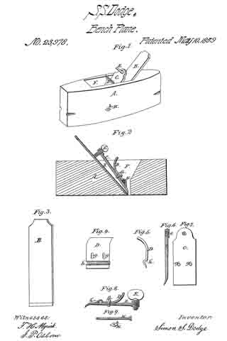
Figure 1, is a prospective view of the plane with the improvements claimed by me. Fig. 2, is a sectional view of the same. Fig. 3, is a plane view of the cutter iron. Fig. 4, is a view of the curved adjustable cop-iron. Fig. 5, is a sectional view of the same. Fig. 6, is a sectional view of the top, or break iron. Fig. 7, is a plane view of the same. Fig. 8, is a sectional view of the adjustable cop iron and the break iron as adjusted for work. Fig. 9, is a view of the bolt and nuts by which the cop iron and break iron are adjusted and confined when in use.
The same letters represent corresponding parts in the various figures.
A, is the stock of the plane.
B, is the cutting iron by which the shaving is removed, and is constructed in its simplest form, as seen in Fig. 3.
C, is the cop, or break iron and is constructed substantially as seen in Figs. 6, and 7.
D, is the curved adjustable cop-iron, and is constructed as seen in Figs. 4: and 5, and is used for the purpose of adjusting the break iron C, and guiding the shaving through the mouth F, of the plane.
E, is a thumb screw which passes through the female screw e, in the break iron C, and serves to keep the latter in place, when properly adjusted for work.
G, represents one of two set screws which pass through the slots g, g, in the adjustable cop iron D, and penetrate the female screws g’, g’, in the break iron C.
H, is a bolt which passes through the stock A, in the groove h in the adjustable cop iron D.
h, is a nut on the side of the stock A, opposite to the head of the bolt H, by which the latter is confined.
In order to adjust the plane for work, the break iron C, is confined to the adjustable cop iron D, by means of the two set screws G, G, (only one of which is shown in the drawings) as seen in Fig. 8. Thus adjusted, the break iron C, and the adjustable cop iron D, are inserted in the mouth F, of the plane, in which they are confined in the right position by means of the bolt H, which passes through the groove h’, and is confined in place by the nut h. The cutter iron B, is then passed into the mouth F, and when properly set for work, is confined lirmly in place by the thumb screw E, which presses upon the upper part of the cutter iron B, bearing the lower edge of the break iron C, firmly down upon the lower portion of the cutter iron B, the bolt H, acting as a fulcrum upon which the break iron C, turns, The cutter iron B, thus adjusted for work, is seen in Fig. 2. By removing the pressure of the thumb screw E, the cutter iron B, may be easily removed, or adjusted for cutting a thicker or thinner shaving, as the work to be done may require.
It is well known that some kinds of timber to be wrought, have nearly an even and regular grain; other kinds have an uneven and irregular grain; and other kinds all knotty and shaky. Some kinds of timber are hard and tenacious; and others are soft and easily wrought. Consequently it becomes necessary that the plane should be adjusted so as to be able to work all kinds of timber with facility and without injury or waste. In working some kinds of timber a thick shaving may be taken off at a single stroke of the plane; and in working other kinds only a very thin shaving can be removed at a single stroke. In order to accommodate the break iron C, to the cutting iron B, so as to enable the latter to accomplish the various work required of it, I have out two slots g, g, in the adjustable cop D, through which the two set screws G, G, above described pass, the latter penetrating the female screws g, g, in the break iron C, as before stated. The slots g, g, permit the set screws G, G, when loosened, to pass freely up and down, thus enabling the operator to so adjust the break iron C, as to cut a thick or thin shaving, as the nature of the work may require, the adjustable cop iron D, being at the same time kept in place by the bolt H.
The advantages of my improvement, are its great simplicity, efficiency, and cheapness. The chip, or wedge, of the plane as ordinarily constructed, is entirely dispensed with. The cutting iron which, in my improved plane, is a plain piece of steel, or iron edged with steel, can be much more cheaply made; and when worn out, or broken, it can be readily removed and another substituted, without the expense of getting a new break iron each time the cutter iron is changed, or substituted. The cutting iron also can be more readily and easily removed from the stock when it requires to be sharpened, and more readily and easily adjusted for its work, than by any other device for the purpose heretofore known until my invention. It is not necessary for the operator to use a hammer about my improved plane. Thus the stock is preserved from the injury which it receives from the blows of the hammer in inserting, adjusting, confining, and removing the cutting iron, in and from it.
Having above fully described my improved hand plane, its construction, and mode of operation, what I have invented and desire to secure by Letters Patent, is —
1. The curved adjustable cop iron D, constructed and operating substantially as above described.
2. The combination of the adjustable cop iron D, with the bolt H, the set screws G, G, and the thumb screw E, and the break iron C, constructed and operating substantially as above described.
SIMEON S. DODGE.
Witnesses:
F. N. MYRIK,
I. P. OSBORN.