No. 739,014 – Bench-Plane (Clinton E. Lincoln) (1903)
UNITED STATES PATENT OFFICE.
_________________
CLINTON E. LINCOLN, OF KINSTON, NORTH CAROLINA.
BENCH-PLANE.
_________________
SPECIFICATION forming part of Letters Patent No. 739,014, dated September 15, 1903.
Application filed December 17, 1902. Serial No. 135,538. (No model.)
_________________
To all whom it may concern:
Be it known that I, CLINTON E. LINCOLN, a citizen of the United States of America, residing at Kinston, in the county of Lenoir and State of North Carolina, have invented certain new and useful Improvements in Bench-Planes, of which the following is a specification, reference being had therein to the accompanying drawings.
My invention relates to certain new and useful improvements in bench-planes, and has for its object a plane which upon its return or idle stroke will automatically lift the cutting-blade sufficiently above the under face of the plane so that the cutting-blade will not scrape along the wood being planed, which, as is well known, dulls the edge of the cutting-blade.
A further object of the in vention is the provision of means whereby the cutting-blade and its supporting mediums may be held in raised position for the purpose of fixedly securing the cutting edge of the blade sufficiently above the under face of the plane in order that the latter may be stored away either in a chest or in a tool-cabinet, thereby preventing any damage being done to the cutting edge of the blade should the plane be in contact with any objects.
Briefly described, the invention may be said to broadly consist of a supporting medium for the cutting-blade, which supporting medium at its one end is suitably pivoted to the plane-stock and at its other end supports the cutting-blade, a handle being arranged on the supporting medium and a spring being interposed between the under side of the supporting medium and the plane-bottom, this spring normally retaining the supporting medium in an elevated position, but possessing sufficient resiliency to enable it to be readily depressed, whereby the cutting edge of the blade may be projected sufficiently within the plane-mouth to enable a shaving to be taken off the object planed when sufficient force or pressure is applied to the handle in order to propel the plane during its cutting-stroke.
With the above and other objects in view my invention further consists in the novel details of construction and combination of parts to be described in the following specification and then set forth in the claims.
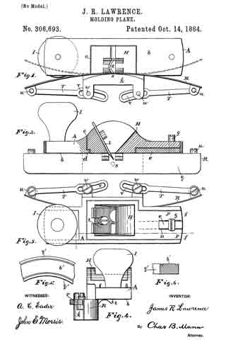
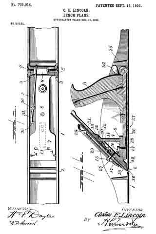
Referring to the accompanying drawings, forming a part of this application, wherein like numerals of reference indicate similar parts throughout the several views, Figure 1 is a top plan view of my improvement, showing the handle removed as well as the intermediate mechanism carrying the cutting-blade; and Fig. 2 is a longitudinal sectional view of the plane embodying my improvements.
The stock of the plane is designated at 1, the bottom of the plane being provided with the usual mouth at 2. At the rear end of the plane and along the sides thereof at opposite points are provided inwardly-extending projections 3, suitably bored and countersunk on their outer sides. Between these projections is received a knuckle 4, which is also suitably bored to register with the bored portions of the projections 3. These registering perforated portions are suitably threaded to receive machine-screws 5, which secure the knuckle with respect to the projections 3 and permit the former to have a free oscillatory movement. This knuckle 4 is the termination of a base-piece 6, which extends transverse to the knuckle and which is materially reduced in width between the knuckle and its forward end 7, the latter being of sufficient width to be readily guided by the sides of the plane-stock. The handle 8 is secured to the rear portion of the base-piece in any approved fashion. This handle and its securing mechanism may be of any of the well-known and common forms in the art.
In order to provide suitable support for the cutting-blade, I secure to the forward end of the base-piece a bracket 8, which consists of a horizontal portion 9, suitably drilled to receive machine-screws 10, which latter pass through drilled and threaded registering portions on the base-piece 6 and which are shown by 11 in Fig. 1. This bracket also embraces a vertical member 12, which at its upper end carries an angularly-disposed integral extension 13 for a purpose shortly to be referred to. The horizontal portion 9 also carries an angular piece 14, whose lower end is adapted to contact with the upper face of the plane-bottom, and thereby limit the downward movement of the base-piece when pressure is applied thereto through the medium of the handle when a forward or cutting stroke of the plane is being carried out. This portion 14 is suitably drilled and threaded and receives in its threaded portion a screw 15, the function of which is well known in the art.
The cutting blade is designated by the numeral 16 and is not of uncommon form, being provided with the usual elongated aperture 17, which is adapted to readily receive the screw 15.
The cap-plate is shown at 18 and is secured to the cutting-blade by means of the screws 19, the cutting-blade having a pivot-point 20, which extends into and is suitably secured to the lever 21, the latter having a screw 22 secured thereto and to the angular extension 13, which permits the lever 21 to rotate about said screw 22 as a point of pivot and through the medium of the pin 20 permits of any necessary lateral adjustment of the cutting-blade.
The clamping-plate is shown at 23 and carries the usual spring-pressed clamping-lever 24, a slot 25 being provided of a slightly elongated nature to readily receive the screw 15.
Under normal conditions, as heretofore stated, the base-piece of the cutting-blade, with its intermediate supporting mechanism, is normally retained in such position as will withhold the edge of the cutting-blade sufficiently above the mouth of the plane for the purpose described, to attain which I provide a flat spring 26, which is suitably secured, as at 27, to the upper side of the plane-bottom and which at its forward end is bowed or arched upwardly, as at 28, and is received within a suitable dug-out portion 29 on the under side of the base-piece 6. This spring is of sufficient strength to readily raise the cutting mechanism from out of the mouth of the plane when pressure is released from the handle.
At the rear end of the plane-body is pivotally mounted, through the medium of a rivet or screw 30, a retaining-lever 31, whose forward end is turned at right angles, as at 32, and is of sufficient thickness to readily enter between the under side of the base-piece and the upper side of the bottom in order that it may thereby support the base-piece and prevent the same from moving in a downward plane should pressure be applied upon the handle or should any object be placed upon the handle or cutting mechanism. This end of the lever will prevent the mechanism from being actuated so as to expose its edge to prevent damage being done to the latter. At its rear end this lever is kicked upwardly, as at 33, and is flattened to provide a thumb-piece 34. A suitable fin 35 is formed integral with the plane-stock and is so positioned as to protect lever 31.
In order to prevent undue upward movement of the cutting-blade and its support, I form integral with the inner sides of the plane-stock lugs 2’, which extend inwardly and are so located as to engage the forward end of the base-piece 6, these lugs being indicated in dotted lines, Fig. 2.
It will be seen that by the use of my improvements during each return or idle stroke of the plane the cutting-bit is automatically raised, so that the latter will not scrape upon the wood or the object being planed, which, as is notoriously old in the art, causes a cutting edge to become rapidly dulled, necessitating frequent whettings, which is obviated entirely by the use of my improvements. Further, I desire to call attention to the fact that by the use of a support for the cutting mechanism of the plane, which upon each stroke of the plane moves in a vertical rotary plane, precludes to a certain extent any clogging of the plane-mouth, which, as is well known, is a frequent occurrence attending the use of any plane, since upon the return or idle stroke of the plane, pressure being released upon the cutting mechanism, the latter will move upwardly and bring the cutting edge out of the mouth of the plane and permit shavings or the like which might have clogged in the mouth of the plane to readily free themselves.
In order to carry into practice the objects of my invention, I have found it necessary to employ certain details of construction which may be readily departed from without affecting the spirit and scope of the invention.
Having thus fully described my invention, what I claim as new, and desire to secure by Letters Patent, is —
1. A plane embodying cutting mechanism and support therefor the said support being pivoted at its one end and carrying the plane-handle, and means interposed between the support and the plane-bottom for holding the support normally elevated.
2. A plane embodying cutting mechanism and support therefor the support carrying the plane-handle at its rear end, and being pivoted at said end, and means adjacent the free end of the support for holding the support normally elevated.
3. A plane embodying a support pivoted at its rear end to the plane-body, and carrying the plane-handle at said end thereof, cutting mechanism on the free end of the support, a means for normally retaining said support in an elevated position, and means pivoted to the plane adapted to engage between the support and plane-bottom for preventing downward movement of the support.
4. A plane embodying cutting mechanism, a support therefor pivoted to the plane, and supporting the cutting mechanism at its forward end, a handle on the rear end of the support, and a spring interposed between the support and the plane-bottom.
5. A plane embodying a base-piece or support, pivoted to the plane and carrying a handle at its rear end, and means for supporting the cutting-blade at its forward end, and means interposed between said base-piece or support and the plane-bottom for normally retaining the base-piece or support in an elevated position.
6. A plane embodying cutting mechanism and a support therefor movable in relation to the plane, and means pivoted to the plane-body adapted to be engaged between the said support and the bottom of the plane to retain the support in an immovable elevated position.
7. A plane embodying cutting mechanism and a support therefor pivoted to the plane, a spring interposed between the said support and the plane-bottom, and a lever pivoted to the plane-body for securing said support against downward movement.
8. A plane embodying a support pivoted at its rear end to the plane-body, and carrying the plane-handle thereon, cutting mechanism on the free end of the support, projections on the plane to engage and limit the upward movement of the support, and means for normally retaining the support in an elevated position.
In testimony whereof I affix my signature in the presence of two witnesses.
CLINTON E. LINCOLN.
Witnesses:
PLATO COLLINS,
INEZ WORTEN.