No. 34,248 – Improvement In Plane Stocks (George Franklin Evans) (1862)
[paiddownloads id=”95″]34248


UNITED STATES PATENT OFFICE.

_________________

GEORGE F. EVANS, OF NORWAY, MAINE.

IMPROVEMENT IN PLANE-STOCKS.

_________________

Specification forming part of Letters Patent No. 34,248, dated January 28, 1862.

_________________

To all whom it may concern:

Be it known that I, GEORGE F. EVANS, of Norway, in the county of Oxford and State of Maine, have invented a new and useful or Improved Plane; and I do hereby declare the same to be fully described in the following specification, and represented in the accompanying drawings, of which —

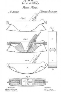
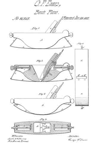
Figure 1 denotes a side elevation; Fig. 2, a longitudinal section of my said plane prepared to operate upon a curved surface having a great degree of curvature; Fig. 3, a side elevation of such plane as prepared to plane on a surface having the slightest curvature; Fig. 4, a horizontal section of the plane, taken through the adjusting-screws and traversing nuts. Fig. 5 is a bottom view of the plane.

The object I had in view in making my invention was to supply a want which has long existed, viz: an instrument which would plane or smoothen any circular concave surface evenly and exactly.

The nature of my invention consists in an improved plane so constructed that its bearing surface or face may be readily adjusted to conform to circular surfaces of different degrees of curvature, whereby such circular parts may be as easily and smoothly planed as a plane surface can be by the ordinary straight-faced plane.

In the drawings, A denotes the stock or body of the plane, the same having a throat or shaving passage B formed vertically through it. In the said passage or throat the plane iron or cutter is secured by means of a wedge C and a cap-plate D in the ordinary manner. Instead of forming the lower face of the stock A as a straight or plane surface,I cause the same to be curved upward in manner as shown in the drawings.

To the lower face of the stock I fasten a flat steel plate E by means of two screws a a, and a bifurcated bar b, whose lower ends extend through the said plate and are riveted thereto, while its other end is secured by means of a screw to the rear part of the throat-passage.

Within the two ends of the stock A and extending longitudinally therein I form two chambers c c’ for reception of two screws G G’ and two traversing nuts H H’, the said screws being supported in stationary bearings d d’, arranged in each end of each of the said chambers c c’. Each of the screws G carries a traversing nut H of a rectangular shape, the said nut being jointed or pivoted at its lower edge with a connecting-rod I, whose lower end is in turnconnected or jointed to the plate E’, the length of the connecting-rods being suoh as to allow the plate E, when the nuts H H’ are at their greatest point of outward extension, to assume or stand in or nearly in a horizontal plane. The screws G or G’ have no longitudinal movement, but are free to revolve on their axes, so as to cause the nuts H H’ to traverse the whole length of their chambers c c’.

A plane constructed in the above-described improved manner can be readily adapted or adjusted to plane or reduce any circular concave piece of wood by simply turning the two screws G G’ in the proper direction.

Having described my invention, I claim —

My improved plane, having its body A, its bearing-plate E, its screws G G’, traversing nuts H H’, and connecting-rods I I, constructed and arranged in relation to each other and so as to operate together, as set forth.

GEORGE F. EVANS.

Witnesses:
LEVI WHITMAN,
RICHARD EVANS.

No. 41,983 – Improvement In Plane Stocks (George Franklin Evans) (1864)

[paiddownloads id=”102″]41893


UNITED STATES PATENT OFFICE.

_________________

GEORGE FRANKLIN EVANS, OF NORWAY, MAINE.

IMPROVEMENT IN PLANE-STOCKS.

_________________

Specification forming part of Letters Patent No. 41,983, dated March 22, 1864.

_________________

To all whom it may concern:

Be it known that I, GEORGE FRANKLIN EVANS, of Norway, in the county of Oxford and State of Maine, have made new and important Improvements in the Plane that was patented January 28, 1862; and I do hereby declare the same to be fully described in the following specification, and represented in the accompanying drawings, of which —

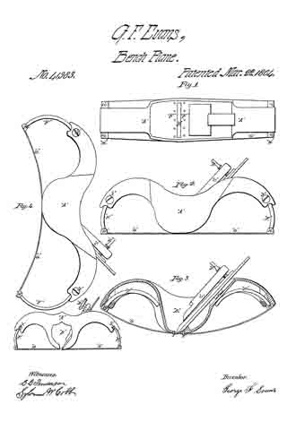
Figure 1 is a plan. Fig. 2 is a longitudinal elevation with the face-plate in a straight position. Fig. 3 is a longitudinal vertical section with the face-plate in a convex position. Fig. 4 is a longitudinal elevation with the face-plate in a concave position or reversed from that in Fig. 3. Fig. 5 is a longitudinal elevation of the rabbet and grooving plane with the face-plate in a straight position.

The nature of my improvement consists not only in the manner of making the stock, but in the combination of the arms which connect the ends ofthe spring face-plate to the stock, the same admitting the spring face-plate to be curved either ccnvexly or concavely on its outer surface. These planes are so constructed that they may be more readily adjusted to conform to concave and convex surfaces of diiferent degrees of curvature, whereby such circular parts may be as easily and smoothly planed, grooved, or rabbeted as a plane surface can be by the ordinary straight taced plane.

In the drawings, A is the stock or body of the plane, the same having a throat or shaving passage, B, formed vertically through it, (horizontally in the grooving-plane, Fig. 5.) In the said passage is the plane-iron, which is secured by the leverchip C and the thumb-screw D.

Instead of forming the lower face of the stock A as a straight plane, I cause the same to be curved upward and downward, in the manner as shown in the drawings. To the lower face of the stock I fasten on a flat steel plate by means of ten steel rivets, E E, on the lower part of the throat-passage — five rivets on the forward part and five rivets on the rear part of the throat-passage, as shown in Fig. 1.

Within the two ends of the stock A pass the connecting-rods F F in the form of a segment of a circle. The lower end of each connecting-rod has a hinge-joint, and is received by a socket or hollow pipe with solid ends, which pipe or socket is fastened to the ends of the steel plate G G by means of two steel rivets, I I. In each end of the stock A is a set-screw, H,which holds the connecting-rods F F in position, as shown in Figs. 2 and 4.

A plane constructed on the above-described improved manner can be readily adjusted to plane any circular, concave, or convex piece of wood; also to groove or rabbet the same by simply bending the plate G to the desired position and securing it by means of the connecting-rods F F and the set-screws J J.

From the above and by inspection of the drawings it will be perceived that my improved plane has its stock formed with two curved ends or projections extending from the part B, which hold the plane-iron, and so adapted to receive the curved arms F F as to allow them to play or move in curved paths both toward and away Ironi the said part B. Now, this mode of making the plane-stock not only enables the spring face-plate to be bent either into a convex or concave form, but it renders the curved ends or projections very convenient as handles by which the plane may be held and operated. Furthermore, they not only give to the connections F F a long range of motion, but keep their upper ends always within the stock when the face-plate is convex on its outer surface, there being no projection of the connections F F above the top surface of the plane-stock when the G is bent to its extreme position, as shown in Fig. 3.

What, therefore, I claim as my invention or improvement in the plane made with the spring face-plate is —

The construction of the connecting-rods F F and their receiving parts of the stock, curved substantially in the manner and so as to operate together as specified.

GEORGE FRANKLIN EVANS.

Witnesses:
HENRY UPTON,
C. C. SANDERSON.