No. 178,256 – Improvement In Carpenters’ Planes (Samuel Williams) (1876)

[paiddownloads id=”263″]178256


UNITED STATES PATENT OFFICE.

_________________

SAMUEL WILLIAMS, OF COLUMBUS, OHIO.

IMPROVEMENT IN CARPENTERS’ PLANES.

_________________

Specification forming part of Letters Patent No. 178,256, dated June 6, 1876; application filed March 15, 1876.

_________________

To all whom it may concern:

Be it known that I, SAMUEL WILLIAMS, of Columbus, in the county of Franklin and State of Ohio, have invented certain new and useful Improvements in Carpenters’ Planes; and I do hereby declare that the following is a full, clear, and exact description thereof, which will enable others skilled in the art to which it appertains to make and use the same, reference being had to the accompanying drawings, and to the letters of reference marked thereon, which form a part of this specification.

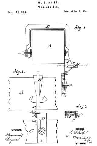
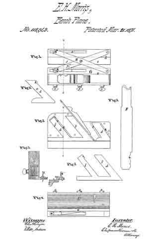
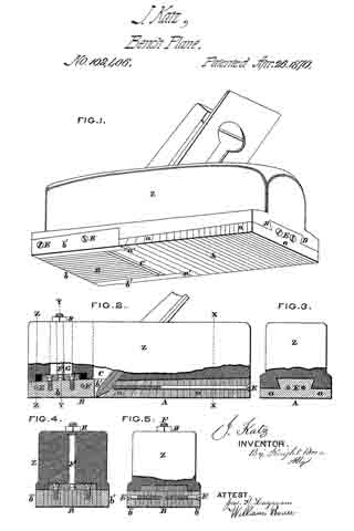
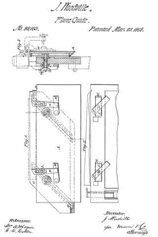
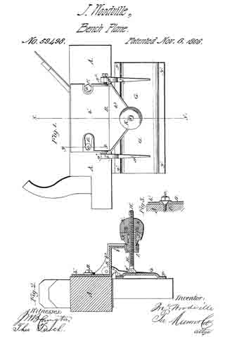
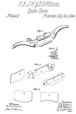
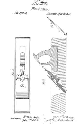
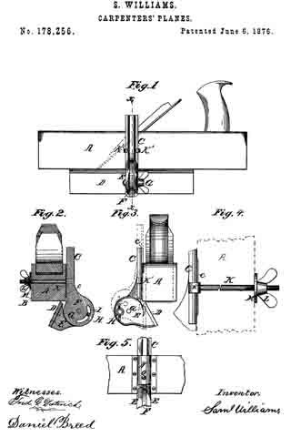
In the accompanying drawings, Figure 1 is a side elevation of a plane with my improvement attached thereto. Fig. 2 is a vertical transverse section of the same on the line x x, Fig. 1. Fig. 3 is an end view, showing the motion of the guide in dotted line. Fig. 4 is a full-sized view of the clutch-bolt and thumb-screw. Fig. 5 shows a detached modification.

My invention consists of certain novel combinations and arrangements of devices for a simple and efficient bevel-guide for planes, the details of which will be fully understood by the following description:

ln the accompanying drawings, A is a plane-stock, with a groove, B, out in each side, to receive the adjustable slide C, which is cast in the same piece with the male part F of the hinge. This slide has a rib, c, which fits the groove B of the plane, in order to prevent the slide from swinging, and thus throwing the bevel-guide out of place. The guide D is attached to the hinge-piece E, which is very strong, and has a slot with broad bearing-sun faces, to grasp the male part F of the hinge, and hold the same firmly in place. This hinge has a central pivot, G, and a set-screw, H, which passes through the curved slot I, Fig. 2, in order to adjust the bevel-guide to any desired angle. A clutch-bolt, K, passes through the plane-stock A, as shown in Fig. 4, and has one end provided with the clutch K’, to grasp the slide C, while the other end is provided with a thumb-screw or nut, L, and washer, M, for fastening the guide to the plane.

The hinge may be graduated in an arc, so as to set the guide D at any desired angle, as is well understood.

Instead of the clutch- bolt K, an arched plate, N, with a set-screw, O, may be used; but I prefer the clutch-bolt shown in Fig. 4.

If necessary with long planes, two clutch-bolts and two hinges may be used to hold the guide more securely in place.

This guide is very simple, and yet strong and durable, and it is very convenient of adjustment, and may be easily changed from one side of the plane to the other, and thus enable the workman to plane cross-grained stuff, and also prevent the uneven wear of the bit.

Having thus described my invention, I claim —

The slide C, provided with the rib c, in combination with the bolt K, bevel-guide D, and plane-stock A, substantially as and for the purposes set forth.

In testimony that I claim the foregoing as my own I affix my signature in presence of two witnesses.

SAML. WILLIAMS.

Witnesses:
DANIEL BREED,
S. E. CARPENTER.

No. 167,943 – Improvement In Plane-Guides (Walter S. Shipe) (1875)

[paiddownloads id=”254″]167943


UNITED STATES PATENT OFFICE.

_________________

WALTER S. SHIPE, OF MINERVA, OHIO.

IMPROVEMENT IN PLANE-GUIDES.

_________________

Specification forming part of Letters Patent No. 167,943, dated September 21, 1875; application filed August 14, 1875.

_________________

To all whom it may concern:

Be it known that I, WALTER S. SHIPE, of Minerva, in the county of Stark and State of Ohio, have invented an Improvement in Plane-Guides, of which the following is a specification:

In the accompanying drawing, Figure 1 represents an end view of my improved plane-guide, and Fig. 2 a side view of the same.

Similar letters of reference indicate corresponding parts.

My invention has for its object to so improve the plane-guide for which a patent has been granted to me under date of January 6, 1874, and numbered 146,208, that it will work more steadily and accurately, and be readily set to any desired angle.

The invention consists, mainly, of a recessed handle-extension of the yoke part in connection with a slotted arc-piece of the guide-strip connecting plate, the arc-piece being pivoted to the yoke, and set by a clamp-screw thereto. A wire key with bent end is inserted into a hole of the guide-strip for being readily available for turning the clamping-screw nuts.

In the drawing, A represents a plane, to which the yoke B is attached in the customary manner by a clamping-screw at one end, and flanged side extensions at the opposite end. The yoke B is cast at the end below the flanges with a handle-extension, E, that is centrally recessed tor the slotted arc-piece D, which forms, with its guide-plate D1, the connection with the guide-strip C. The slotted arc D extends at right angles from guide-plate D1, and is inserted and pivoted at its center in the handle-extension E. A set-screw, E’, passes through the perforations of the handle E and the slot of the arc-piece for the purpose adjusting the sliding arc to any required angle. The outer circumference of the arc-piece D is graduated, so that the same may be directly set with the guide-strip C to any required degree of inclination toward the plane. The guide-plate D1 is slotted and adjusted in a recess of the guide-strip C, nearer to, or farther from, the plane by a set-screw, D2. A key, F, of strong wire, with bent end is inserted into a socket-hole of guide-strip C, being slightly curved at its longer part to be retained there in with a certain tension without falling out, the shorter bent end serving as handle to withdraw it from the guide-strip. The wire key F is inserted into perforations of the heads of the set-screws, so that they can be easily loosened or tightened, while the key may be securely put away into the socket-hole of the guide-strip without getting lost. The key is thus always at hand tor use for setting the plane-guide, which is steadily and firmly adjusted in the handle-extension or socket-piece of the yoke.

Having thus described my invention, I claim as new and desire to secure by Letters Patent —

The combination, with a guide-strip, C, of plane-clamping yoke B, having recessed extension E, the pivotted slotted arc-piece D, and the clamp-screw E’, as and for the purpose specified.

WALTER S. SHIPE.

Witnesses:
JOHN BREIDENSTEIN,
A. N. BOORY.

No. 165,132 – Improvement In Guides For Bench-Planes (Harrison P. Taylor) (1875)

[paiddownloads id=”245″]165132


UNITED STATES PATENT OFFICE.

_________________

HARRISON P. TAYLOR, OF MINERVA, OHIO, ASSIGNOR TO HIMSELF AND P.
A. PAINTER, OF SAME PLACE.

IMPROVEMENT IN GUIDES FOR BENCH-PLANES.

_________________

Specification forming part of Letters Patent No. 165,132, dated June 29, 1875; application filed May 28, 1875.

_________________

To all whom it may concern:

Be it known that I, HARRISON P. TAYLOR, of Minerva, in the county of Stark and State of Ohio, have invented an Improvement in Guides for Bench-Planes, of which the following is a specification:

Figure 1 represents a perspective view of my improved plane-guide, as attached to a plane. Fig. 2 is an end view, and Fig. 3 a vertical section, of the same on the line c c, Fig. 2.

Similar letters of reference indicate corresponding parts.

The object of my invention is to provide an improved double adjustable plane-guide that may be readily set to any angle, and to any part on the face of the plane, that the whole width of the bit is used and the true face of the plane preserved.

The invention consists of a rectangular slotted or dovetailed piece that is attached to the side of the plane, and provided with a sliding piece, with guide-arms tor the pivoted, graduated, and slotted piece, which is set by a clamp screw, and attached by a slotted base-plate to the beveled guide-strip.

In the drawing, A represents the rectangular piece, by which the guide is attached to the side of the plane by a set-screw, B, passing through a slot or perforation of the same. The free end of piece A is either provided with a dovetail groove at the under side, or with a plain slot tor the purpose of guiding the sliding rectangular piece C, having dovetail or tongue, into any position, to any point on the face of the plane, or in opposite direction to some distance from the same, as required. The sliding piece C is firmly secured when adjusted by a set-screw, C1. The downward-extending part of slide-piece C forms, by a dividing recess, two guide-arms or standards, C2, between which the quadrantal piece D is pivoted, and by means of slot a and set-screw b set to any angle toward the face ofthe plane, according to the graduation of its circumference. A base-plate, D’, at right angles to the quadrantal part, carries, by slot and clamp-screw, a beveled wooden or iron guide-strip, F, which may be brought up to the edge and face of the plane. One or two guides may be used, according to the length of plane or material. The guide attachment is removed by detaching the fastening-screw of the rectangular piece A from the side of the plane, or by leaving the same on the plane, using it as a handle, and taking off the slide-piece with the rest of the attachment.

The guide may be adjusted to use the plane square or at any bevel, the main advantage being the sliding of the guide-strip under the face of the plane.

Having thus described my invention, I claim as new and desire to secure by Letters Patent —

The combination of plate A, slide C, single set-screw C1, and quadrant D, all constructed and arranged as and for the purpose specified.

HARRISON P. TAYLOR.

Witnesses:
JOHN BREIDENSTEIN,
HERBERT NICKELSON.

No. 146,208 – Improvement In Plane-Guides (Walter S. Shipe) (1874)

No. 146,208 – Improvement In Plane-Guides (Walter S. Shipe) (1874)

[paiddownloads id=”224″]146208


UNITED STATES PATENT OFFICE.

_________________

WALTER S. SHIPE, OF MINERVA, OHIO.

IMPROVEMENT IN PLANE-GUIDES.

_________________

Specification forming part of Letters Patent No. 146,208, dated December 18, 1874; application filed November 15, 1873.

_________________

To all whom it may concern:

Be it known that I, WALTER S. SHIPE, of Minerva, in the county of Stark and State of Ohio, have invented a new and Improved Plane-Guide, of which the following is a specification:

In the accompanying drawing, Figure 1 represents a sectional end view of my improved plane-guide as applied to a plane. Fig. 2 is a side view of the same 5 and Fig. 3, a detail horizontal section of the wide pivot on the line c c, Fig. 1.

Similar letters of reference indicate corresponding parts.

My invention relates to an improvement in plane-guides by which the plane is steadied in squaring or beveling to any desired angle without the use of a try-square or bevel; and consists of a yoke, which is firmly applied to the plane, and provided, at one end, with a pivoted guide-strip, which is adjusted by clamping-screws under any required angle to the plane.

In the drawing, A represents the plane; B, the yoke; and C, the guide-strip. The yoke B is rigidly applied to plane A by means of a clamp-screw, a, at one side, and a flanged extension, b, at the other side. The guide-strip C is applied to a connecting-piece, D, which is pivoted, by its semicircular part d, to the outwardly-projecting end of yoke B, below flanges b. The semicircular part d is beveled along its circumference, divided by degrees, and rigidly set to any angle to the plane by a curved wedge-piece, e, which is tightly secured between part d and the beveled projection g, at the outer end of yoke B, by a set-screw, f The slotted extension-piece D projects at a right angle to the semicircular part d, and slides in a recess, h, of guide-strip C, so that it may be carried up to the base of the plane, to be firmly secured by a fixed set-screw and washer, l.

When the plan is to be used with the guide for squaring, beveling, or jointing boards, veneers, &c., the yoke is placed over the plane, and firmly screwed thereon in such a manner that the center of the semicircular part d is slightly below the base of the plane. The set-screw at the edge of the are is then loosened, which allows the swinging of the guide-strip to any desired angle. If the angle between the guide-strip and base of the plane is oblique, the set-screw in the slotted part of piece D is loosened, to give greater play to the guide. When the guide is in position, the set-screw and wedge at the arc are tightened, and the guide moved up till it touches the base of the plane. The set-screw of the guide is then tightened on the slotted piece, and the plane ready for use, saving time and labor, and allowing of various applications in the trade.

Having thus described my invention, I claim as new and desire to secure by Letters Patent —

1. The plane-guide consisting of yoke B, with clamping- screw a, pivoted connecting-piece D, curved wedge-piece e, and guide-strip C, with fixed setscrew l, arranged and applied substantially as and for the purposes described.

2. The yoke B, having projecting end, forming the seat of the semicircular part d of piece D, and beveled projecting lug g, as set forth.

WALTER S. SHIPE.

Witnesses:
E. W. POORMAN,
GEO. W. PATTON.

No. 137,329 – Improvement In Wood-Scrapers (Henry D. Spickler) (1873)

[paiddownloads id=”209″]137329


UNITED STATES PATENT OFFICE.

_________________

HENRY D. SPICKLER, OF CANTON, OHIO.

IMPROVEMENT IN WOOD-SCRAPERS.

_________________

Specification forming part of Letters Patent No. 137,329, dated April 1, 1873; application filed December 5, 1892.

_________________

To all whom it may concern:

Be it known that I, HENRY D. SPICKLER, of Canton, in the county of Stark and State of Ohio, have invented certain new and useful Improvements in Wood- Scrapers; and that the following is a full, clear, and exact specification thereof, which will enable others skilled in the art to make and use the said invention.

My invention relates to the construction of a tool for scraping and smoothing the surface of wooden implements, such, for instance, as ax-handles, spokes, &c., after they have been worked into the desired shape by means of a lathe or other machinery for accomplishing that object. It consists of a metal frame, having a handle cast or otherwise attached at each end, and having two longitudinal slots, in which are secured knives with scraping-edges, one of a straight and the other of a curved form, which are arranged at such an angle with the bottom faces of the frame, and with their edges at such distances from said bottom faces, as to cause the said knives to act as scrapers on the article to be operated on, when the tool is drawn over said article after the manner of using the ordinary spoke-shave. This scraper is applicable to nearly all the uses to which the common plate scraper is applied, while it is much easier to operate and does better work than the common scraper.

In the accompanying drawing, Figure 1 is a top view of the scraper; Fig. 2, a bottom view of the same 5 Fig. 3, a view of that side of the scraper used for curved surfaces; Fig. 4, a view of the side used for straight surfaces; and Fig. 5, a vertical cross-section of the same.

A is the metal frame, having handles a a cast on it. D and E are knives inserted in slots F F, and having their edges d and e turned forward, like the ordinary scraper, the knife E having a curved lower edge, e, while the edge d of the knife D is straight. The knives D E are held firmly in place by means of the wedges f f driven into holes in the frame, the edges of said knives projecting slightly below the bottom-faces B C of the frame. The slots F F in which the knives are placed are made of a triangular section, to receive the scrapings thrown up by the knives. The base of the frame A is inclined from the middle toward the sides, as shown at B and C, Figs. 2 and 5, the face being also curved longitudinally, to correspond to the shape of the knife E, and adapt it to use on curved surfaces. On applying either knife to a wooden surface, the inclination of the base inclines the knife, so that the angle D d c or E e b formed by the knife with the surface toward whichit is moving will be less than a right angle, the acuteness of the angle depending on the amount of inclination of the base, by which means the scraping or turned-up edges d e of the knives are brought at the proper angle to act on the wood, as will be readily seen.

In using the scraper, the operator draws the tool over the wood with the knife d forward, when he wishes to use the straight cutting-edge, and in the opposite direction when the curved edge e is desired, only one cutting edge being in operation at one time, as will be seen from the form of the cross-section shown in Fig. 5.

I lay no claim to a scraper constructed with a single scraping-knife, as such device has been heretofore shown in Letters Patent granted to F. A., J. H., and D. C. Williams, July 24, 1866, No. 56,651, and I confine my claim to a double scraper, having a straight knife on one side and a curved knife on the other, as herein shown.

What I claim as my invention, and desire to secure by Letters Patent, is —

The double scraper herein described, consisting of a frame, A, with handles a a, in which are secured two knives, D E, with turned or scraping edges d e, said knives being arranged back to back, and on opposite sides of the frame A, and one of said knives, D, having a straight, and the other knife, E, a curved edge, substantially as and for the purpose specified.

As evidence of the foregoing, witness my hand this 4th day of November, A. D. 1872.

HENRY D. SPICKLER.

Witnesses:
JOB ABBOTT,
JENNIE M. GRANT.

No. 142,216 – Improvement In Planes For Cutting Cigar-Lighters (William H. Drips) (1873)

[paiddownloads id=”215″]142216


UNITED STATES PATENT OFFICE.

_________________

WILLIAM H. DRIPS, OF CINCINNATI, OHIO.

IMPROVEMENT IN PLANES FOR CUTTING CIGAR-LIGHTERS.

_________________

Specification forming part of Letters Patent No. 142,216, dated December 18, 1873; application filed June 24,1873.

_________________

To all whom it may concern:

Be it known that I, WILLIAM H. DRIPS, of Cincinnati, Hamilton county, State of Ohio, have invented a certain new and useful Plane for Cutting Cigar-Lighters, of which the following is a specification:

My invention consists of a small frame, to be placed temporarily upon a table or on the counter of a saloon, cigar-shop, hotel, or other similar place where cigars are sold, the frame containing a fixed plane blade and gage, by means of which the attendant can, with but little labor, make a sufficient number of curled shavings, adapted for cigar-lighters, to form a sufficient stock for the day.

Figure 1 is a general view of my improved tool, showing the method of using my invention. Fig. 2 is a perspective vievv of the tool. Fig. 3 is a plan of the cutter-blade. Fig. 4 is a vertical section of a portion of the frame and cutter-blade.

A is a frame, formed of two strips, A’ A”, of wood, attached at right angles to each other, as shown. The horizontal strip, which rests upon the table or counter, has at one end a lip or flange, a, to engage the edge of the table and prevent it from slipping, said lip being preferably formed in one piece with the strip A’. A cutter-blade, B, of steel, is let obliquely into the plate A’, and secured permanently thereto at each end by screws. Below it is a circular recess, C, which receives the coiled shavings, and allows it to pass out upon the counter. The cutter B is not only let in obliquely in the direction of its length, but is also obliquely located in the direction of its width, so as to cause the shavings to curl anglevvise by its obliquity lengthwise, and cause the knife to present a cutting-edge by its obliquity crosswise. A gage or shield, D, is attached to strip A’ by screws d, the gage being slotted, as shown, to permit adjustment to suit different thicknesses of stud to be cut. This shield prevents the operator’s fingers from touching the knife in the act of pushing the stuff along, in the manner shown, to cut the lighters. The instrument may, however, be made and used without the adjustable gage.

I claim —

As a new article of manufacture, the tool for cutting cigar-lighters, substantially as described.

In testimony of which I hereunto set my hand.

WILLIAM H. DRIPS.

Witnesses:
FRANK MILLWARD,
J. L. WARTMANN.

No. 145,106 – Improvement In Bench-Planes (George W. Huber And Aaron E. Flickinger) (1873)

[paiddownloads id=”221″]145106


UNITED STATES PATENT OFFICE.

_________________

GEORGE W. HUBER AND AARON E. FLICKINGER, OF NORWALK, OHIO.

IMPROVEMENT IN BENCH-PLANES.

_________________

Specification forming part of Letters Patent No. 145,106, dated December 2, 1873; application filed October 18, 1873.

_________________

To all whom it may concern:

Be it known that we, GEORGE W. HUBER and AARON E. FLICKINGER, of Norwalk, in the county of Huron and State of Ohio, have invented a new and Improved Plane, of which the following is a specification:

In the accompanying drawing, Figure 1 represents a vertical longitudinal section of our improved plane; and Fig. 2, a vertical transverse section of the same on the line c c, Fig. 1.

Similar letters of reference indicate corresponding parts.

The object of our invention is to construct an improved plane, which is light, handy, and easily adjustable to any thickness of shaving without the use of a hammer. Our invention consists in the firm mounting of the plane-iron between a cap-piece with connecting clamping-bolt and set-screw, and a supporting-shoe, which is pivoted to the sides of the base-piece, and adiusted, together with the plane-iron, by a conical eccentric pivoted to the base.

In the drawing, P represents the base-piece of the plane, provided with front and rear handles H, and made preferably of cast-iron. The shoe B is pivoted at a to the side flanges of base A, and supports on its inclined front part the plane-iron D, while the backward-extending bracket-shaped sides rest with their broader ends on rubber cushions b, by which a certain degree of spring action is imparted to shoe B, so as to offer a yielding support to the plane-iron. The face part of shoe B is provided with a recess, d, and extension-slot e, for giving play to the screw-head d’ of the plane-iron D and clamping-bolt f of the cap-piece A. The plane-iron D has a perforation, f’, for the passage of bolt f. A conical eccentric, C, is pivoted to a lug, g, of base P, under the lower extremity of shoe B, and produced under the same inclination of its sides as the front part of shoe B, so as to raise or lower shoe B, as the eccentric C is turned, by means of its handle C’. The plane-iron is thus raised or lowered with shoe B, and the thickness of the planing regulated thereby. The slot through which the plane-iron projects is widened on lowering the iron, so that the thicker shavings may freely pass through the same; while, in raising the iron, the slot is narrowed in proportion to the thinner shavings, and thus the tearing up of the wood or the veneers prevented, and a neat and smooth surface produced. The cap-piece A is placed on the top of the plane-iron D, its clamp-bolt f passing through the slotted part of the iron and into slot e of shoe B. The sides of bolt f are recessed to correspond exactly to the width of slot e, while its broad head projects over the sides of slots e, and holding thereby the plane-iron and shoe in position. By means of a set-screw, h, at the upper end of cap A, the shoe B may be firmly tightened on the iron D, clamping it rigidly between cap A and shoe B. The plane iron is in this manner easily and firmly set into the plane, and readily adjusted to any degree of planing in a neat and convenient manner, economizing time, and forming a compact and strong implement for the trade.

Having thus described our invention, we claim as new and desire to secure by Letters Patent —

The improved adjustable plane, consisting of base-piece P, pivoted shoe B with rubber cushions b, conical eccentrics C C’, perforated plane-iron D, and clamping cap~piece A, constructed substantially as and for the purpose as described.

GEORGE W. HUBER.
AARON E. FLICKINGER.

Witnesses:
E. R. JACKSON,
T. H. KELLOGG.

No. 112,949 – Improvement In Molding-Planes (Ellis H. Morris) (1871)

[paiddownloads id=”182″]112949


United States Patent Office.


ELLIS H. MORRIS, OF CANTON, OHIO.

Letters Patent No. 112,949, dated March 21, 1871.
_________________

IMPROVEMENT IN MOLDING-PLANES.

_________________

The Schedule referred to in these Letters Patent and making part of the same.

_________________

To all whom it may concern:

Be it known that I, ELLIS H. MORRIS, of Canton, in the county of Stark and State of Ohio, have invented a new and valuable Improvement in Molding-Planes; and I do hereby declare that the following is a full, clear, and exact description ofthe construction and operation of the same, reference being had to the annexed drawing making a part of this specifcation and to the letters and figures of reference marked thereon.

Figure 1 of the drawing is a top view of my plane;
Figure 2 is a side elevation, with the side plate removed;
Figure 3 is a vertical transverse section;
Figure 4 is a bottom view; and Figures 5, 6, and 7 are details.

My invention has relation to an improvement in planes; and It consists in providing a plane-stock with an adjustable face, capable of being molded or shaped to suit a plow-bit of any form; also, in attaching to the plane-stock an adjustable extension-gauge, designed to enable the bit to be run at any desired distance from the edge of a board or panel, as hereinafter described.

The letter A of the drawing designates my plane-stock, which may be similar in its external form to the ordinary plane-stocks in common use. The under side of the stock is channeled or excavated from side to side to receive the thin vertical sections which constitute the adjustable face of the stock.

B B represent elongated recesses or ways extending up into the body of the plane-stock, from the channel at the base, at an angle of forty-live degrees, or corresponding to the angle of the bit. These recesses serve to receive the offsets from the face-sections, presently to he described. Usually I make one of these recesses in front of the throat of the plane, and two in rear thereof.

C designates the adjustable face of my plane-stock. This is composed of two sets of thin vertical strips d, running in the direction of the length of the plane-stock. One set of these strips is situated in front ot the bit and the other is placed in rear, following the bit.

Each strip of the first set is provided with an offset or guiding-arm, e, which extends upward and backward at an angle of forty-five degrees, or parallel to the bit, into the recess B.

Each stern e is provided with a projection, h, at its upper forward corner, which is designed to engage with a stop, k, in the wall of the recess. The arm e is arranged to slide up and down in its recess, the distance to which it can descend being regulated by the position of the stop it and the projection h.

Each strip of the second or rear set is provided with two guiding-arms f f’, extending upward and rearward, parallel to the arm of the strip in front of the bit, which immediately precedes it.

The forward arm f’ of the rear strip is without a stop, and slides in a recess formed in the rear wall or the throat of the stock.

The rear arm f is similar to tue arm e ofthe forward strip, being provided with a projection, and arranged to engage with a stop in the wall of its recess which limits the descent of the strip. These stops k are placed in the recesses in such a position that they will allow the strips to descend as far as the lowest point of any one of the ordinary plow-bits in use.

These strips or sections d are usually made thin, in order that they may conform as closely as possible to the configuration of the edge of the bit. The face-edge of each strip is transversely rounded, or beveled on each side.

D D represent set-screws, passing through the wall of the plane-stock, and serving to secure the strips in their relative position to each other and to the bit after they have been properly adjusted and molded in form.

E represents my bit, which is provided with a means of shaping the adjustable face of the stock to suit its cutting-edge.

This consists of a notch or indentation, a, formed in its upper edge, and corresponding precisely in shape with the edge of the bit, with the exception that the general curve or profile is reversed and flatter.

The face-sections having been adjusted out to fill the mold the set-screws are tightened, and the strips thereby rigidly secured in position.

The bit and wedge are now inserted in the throat of the plane-stock, and, having been properly adjusted, the tool is ready for operation.

This stock, with its adjustable face, may be used with a stationary gauge, but usually I prefer to attach to it my extension-gauge, as follows:

At the base of the exterior wall of the stock, on the left or inner side, is formed a projecting ledge, G, which extends usually the entire length of the stock.

At the forward end a circular projection is raised, which serves as a bearing for the inner end of the extension-bar H.

A slot, l, traverses longitudinally the rear portion of the ledge G.

The under side of the ledge G is recessed at v v, on each side of the slot l, to receive the flanches of the nut n.

K represents a clamp-screw, by means of which the inner end of the extension-bar H’ is pivoted to the ledge G. The end of this clamp-screw passes through the slot l, and, engaging with the square nut iz, serves to hx the bar H’ in any desired position.

The bars H and H’ cross each other, and are pivoted together at about their middle portions by the pivot r. The outer end of the bar H is bent downward in order to bring it on a level with the outer end of the bar H’.

Z represents the movable gauge-bar. The upper and inner corner of this bar is recessed at s to receive the ledge G, thus permitting the face z’ of the gauge to be brought up close to the bit, when desirable.

The outer end of the bar H’ is pivotcd to the forward end of the gauge-bar Z.

The rear end of the gauge-bar Z is slotted at l’ to receive a clamp-screw, K’, which operates, in conjunction with a nut, n’, to secure the outer end of the bar H at any point of the slot.

The distance to which the gauge can be extended from the bit is regulated by the length of the cross-bars H H’ and the length ofthe slots l l. The gauge-bar, when adjusted at the proper distance from the bit, can be rigidly fixed in that position by means of the clamp-screws K K’.

A plane constructed in this manner is designed to subserve purposes of great importance to cabinet-makers and carpenters. To journeymen especially it will prove a great convenience in the saving that will ensue in transportation, one stock being sufficient for all the bits that they may employ. Carpenters, even of small means, can execute a great variety of moldings, limited only by the number of different bits which they may possess.

What I claim as my invention, and desire to secure by Letters Patent, is —

1. A plane-stock, having an adjustable face, capable of being varied in form to suit bits having differently-shaped cutting-edges, substantially as specified.

2. The combination, with a plane-stock provided with a slotted ledge, G, of the slotted gauge Z, cross-extension arms H H’, and clamps K K, substantially as specified.

3. The combination, with a plane-stock having an adjustable face, of a bit provided with a forming indentation, substantially as specified.

In testimony that I claim the above I have hereunto subscribed my name in the presence of two witnesses.

ELLIS H. MORRIS.

Witnesses:
L. W. JONES,
J. H. LIDDALL.

No. 109,037 – Improvement In Planes (Ellis H. Morris) (1870)

[paiddownloads id=”174″]109037


United States Patent Office.


ELLIS H. MORRIS, OF SALEM, OHIO.

Letters Patent No. 109,037, dated November 8, 1870.
_________________

IMPROVEMENT IN PLANES.

_________________

The Schedule referred to in these Letters Patent and making part of the same.

_________________

To whom it may concern:

Be it known that I, ELLIS H. MORRIS, of Salem, in the county of Columbiana and State of Ohio, have invented a new and useful Improvement in Metallic Planes; and I do declare that the following is a true and accurate description thereof, reference being had to thc accompanying drawing and to the letters of reference marked thereon, and being a part of this specification, in which —

Figure 1 is a perspective view of my improved plane.
Figure 2 is a plan of the bottom.
Figure 3 is a longitudinal vertical section of the device.

Like letters indicate like parts in each figure.

The nature of this invention relates to an improved construction of metallic planes, whereby greater lightness and strength are secured, with case in operation.

The invention consists in casting the body of the plane with a series of intersecting ribs, covering the entire face, and in the general arrangement of its several parts, as more fuily hereinafter described.

In the drawing —

A represents a thin iron plate, cast with narrow projecting and intersecting ridges, a, on its lower face, and a rib-socket, A’, on its upper surface, which, besides giving the plane-body the necessary rigidity, receives thc handle B at the rear end, secured therein by two or more bevel-screws, b, whose heads are countersunk in the cavities formed by the ridge a.

The central portion of the socket forms the throat c, and in the forward part is secured a knob, C, by which the operator guides the plane.

D is the plane-iron, whose slot, d, extends to the upper end.

E is the cap, resting on the upper or forward face of the iron, to which it is secured by a set-screw, F, threaded in it, passing from the rear side of the iron through the slot d.

G is the wedge, which secures the iron and cap in the throat in the usual manner.

By extending the slot in the iron to its upper end, when I wish to remove it for sharpening, I simply loosen the thumb-screw F, when the iron drops down through the throat. In like manner it is readjusted.

This construction of the body of the plane combines great strength and rigidity with the minimum of weight. The weight of all metallic planes hitherto made has been the principal objection to their use, seconded by their large cost as compared with the wooden plane.

In making such planes, after the bottom is cast it is the custom to level off the face on an iron-planer, and finish on an emery-wheel — an expensive process.

In this, as soon as taken from the sand I put it in a vise and finish the surface with a file, at a tenth of the cost of finishing a plane-face by the other method, as the peculiar arrangement of the intersecting ridges leaves but little metal to be removed in order to face the plane. For the same reason the plane is easier to move on the wood, the diminished area ofthe surface moving in contact with the board reducing the friction in a corresponding ratio.

I do not wish to confine myself to the particular configuration of the face-ridges shown, as the same may be in curved lines, intersecting each other to term any desired geometrical pattern.

I am well aware that cast-iron planes have been made with longitudinal grooves planed in their faces, and therefore disclaim the invention of such.

What I claim as my invention, and desire to secure by Letters Patent, is —

1. The intersecting ridges d on the face of a metallic plane, as described.

2. The arrangement of the handle B, knob C, plane-iron D, cap E, screw F, and wedge G, with the metallic plane-body A, constructed as herein described, and operating as set forth.

ELLIS H. MORRIS.

Witnesses:
MARMADUK WILSON,
SAMUEL HARDMAN.

No. 102,406 – Improvement In Plane-Stock (Julius Katz) (1870)

[paiddownloads id=”164″]102406


United States Patent Office.


JULIUS KATZ, OF CINCINNATI, OHIO.

Letters Patent No. 102,406, dated April 26, 1870.
_________________

IMPROVEMENT IN PLANE-STOCK.

_________________

The Schedule referred to in these Letters Patent and making part of the same.

_________________

To all whom it may concern:

I, JULIUS KATZ, of Cincinati, Hamilton county, Ohio, have invented a new and useful Improvement in Plane-Stocks, of which the following is a specification.

Nature and Objects of the Invention.

My invention relates to an improved facing device for wood-workers’ plane-stocks.

General Description with Reference to the Drawings.

Figure 1 is a perspective under-side view of a plane-stock. embodying my improvement.
Figure 2 is a partly-sectionized side elevation thereof.
Figures 3, 4, and 5 are transverse sections at the lines X X, Y Y, Z Z, respectively.

I make the entire under surface of my improved plane-stock to consist of blocks or strips of bone, ivory, or similar hard organic substance, glued together in two pieces or slabs, A and B, of which the slab A, in rear of the throat C, fits, and occupies a dovetail excavation, D, on the under side of the wooden portion Z of the stock, to which it is firmly glued.

The component strips a and b of either slab are also firmly glued together, and additionally secured together by screws E.

The slab B, instead of being immovably fastened to the stock, is made capable of a slight longitudinal adjustment, and, for this purpose, is surmounted by a bolt or stern, F, which, extending upward through a slot, H, in the plane-stock, is secured by a nut, G, on the top of the stock.

Of the strips which compose the shiftable piece, B, the two outside ones, b’ b’, project rearward from the others, and enter jogs or gains a’ in the slab A.

Claim.

I claim herein as new and of my invention —

Facing a plane-stock with a congeries of strips of bone or like substance, glued and screwed together and fastened to the stock proper in the manner set forth.

In testimony of which invention I hereunto set my hand.

JULIUS KATZ.

Witnesses:
GEO. H. KNIGHT,
JAMES H. LAYMAN.

No. 88,109 – Improvement In Plane-Guide (John Woodville) (1869)

[paiddownloads id=”150″]88109


United States Patent Office.


JOHN WOODVILLE, OF CINCINNATI, OHIO.

Letters Patent No. 88,109, dated March 23, 1869.
_________________

IMPROVEMENT IN PLANE-GUIDE.

_________________

The Schedule referred to in these Letters Patent and making part of the same.

_________________

To all whom it may concern:

Be it known that I, JOHN WOODVILLE, of Cincinnati, in the county of Hamilton, and State of Ohio, have invented a new and useful Improvement in Plane-Guide and Holder; and I do hereby declare that the following is a full, clear, and exact description thereof, which will enable others skilled in the art to make and use the same, reference being had to the accompanying drawings, forming part of this specification, in which —

Figure 1 represents a back-side elevation of my improved apparatus;
Figure 2 represents afront-side elevation, with a part broken away; and
Figure 3 represents a transverse section taken on the line x x of fig. 1.

Similar letters of reference indicate like parts.

The object of this invention is to provide an adjustable holder, or clamp, for holding strips, for dressing them, and which will also serve as a guide for straightening or tapering them. It is designed more particularly to be used with the improved joiners’ plane, patented to me, November 6, 1866.

It consists of a holding-strip, or board, which is designed to be secured to a bench, with one edge upward, and which is provided with an adjustable gauge upon one side, against which the strips to be planed are clamped, by buttons and wedges on the other side of the first-mentioned holding-strip.

A represents the holding-strip, which may be secured to a bench, or in a vise, in any suitable manner, with the edge B upward.

C represents a guide and clamping-strip, which is provided with the T-headed inclined grooves D, whereby it is clamped to the strip A, by the bolts E and thumb-nuts E’; the heads F of the said bolts being arranged loosely thereon, and sliding in the wide part of the grooves D.

The holes through the strips A are elongated, and provided with the hollow bolts I, having enlarged heads arranged in the recesses H. The bolts E pass through these hollow bolts, and the office of the latter is to serve as rigid supports for the former when adjusted to the light position, and screwed up tightly by the nuts I’.

K represents clamping-buttons adjustably connected to the front face of the strip A, by the long bolts L; and

M represents wedges pivoted to the face of the strip A, in a position to be conveniently adjusted under the inclined ends of the buttons, for clamping them against the stuff to be operated upon.

The operation is as follows:

When it is designed to dress a strip with parallel and square edges, the guiding-strip C, which is provided with one edge a, and one bevelled edge b, is adjusted to the strip A, with the square edge a as high above the strip A as the designed width of the strip to be dressed the edge a being in a horizontal plane parallel with the edge of the strip A when it is clamped tight thereto by the bolts E and thumb-nuts E’.

The strip to be dressed is then placed upon the upper edge of the strip A, and clamped between the guide C and the buttons K.

The plane, which, according to the improvements patented to me as above described, is provided with an adjustable guide, d, is then placed upon the strips to be dressed, and held by the said guide, so that the edge e of the stock will project over the guide C sufficiently to arrest the cutting-action of the plane when the strip has been worked down to the point coincident with the edge of the guide C.

Any number of strips may thus be dressed to the same gauge with great uniformity, while at the same time the edges will be exactly square, if the plane-guide be adjusted to that angle.

If it is desired to dress the strips with bevelled edges, the bevelled edge b, of the guide G, is placed upward, as represented in blue lines, at b’; and if it be desired to produce tapered strips, the guide C may be adjusted to produce any taper, by loosening the bolts E and I, so as to allow the plates I to move in the recesses H, to correspond with the varying distances caused between the points of contact with the grooves D, of the heads of the bolts E, by changing the horizontal plane of the guide C.

In dressing thin strips, two or any other number, not wider in the aggregate than the plane-bit, may be clamped together, and dressed at once.

In dressing strips in this manner, in my improved guide and holder, with my improved planes, I have found it very desirable to provide the jack, or roughing-plane with an adjustable gauging-strip, f, as shown in red in fig. 3, for the purpose of arresting the cutting-action of the plane-bit, the amount of a few shavings, before the strips are brought down to a level with the upper edge of the guide C, so that the roughing-plane may be removed in time to finish the work by the jointer, which I provide with a similar guide, d, but not with the guide f

The latter may be adjustably connected to the stock, so that, as the latter wears away, it may be adjusted thereon.

I am aware that clamps have already been arranged upon carpenters’ benches in such a rnanner as to be adjustable for cutting different widths of boards with square or bevelled edges.

Having thus described my invention, I claim as new, and desire to secure by Letters Patent —

1. The combination of the clamping-bolts E and the sliding bolts I, with the supporting-strip A and grooved strip C, whereby said strips are held together, for dressing a board with either parallel or tapering sides, substantially as herein shown and described.

2. The combination, with the strips A and G, of the adjustable buttons K and pivoted wedges M, substantially as and for the purpose set forth.

JOHN WOODVILLE.

Witnesses:
FRANK BLOCKLEY,
ALEX. F. ROBERTS.

No. 59,498 – Improvement In Carpenters’ Planes (John Woodville) (1866)

[paiddownloads id=”120″]59498


UNITED STATES PATENT OFFICE.

_________________

JOHN WOODVILLE, OF CINCINNATI, OHIO.

IMPROVEMENT IN CARPENTERS’ PLANES.

_________________

Specification forming part of Letters Patent No. 59,498, dated November 6, 1866.

_________________

To all whom it may concern:

Be it known that I, JOHN WOODVILLE, of Cincinnati, in the county of Hamilton and State of Ohio, have invented a new and useful Improvement in Jointing-Planes; and I do hereby declare that the following is a full, clear, and exact description thereof, which will enable others skilled in the art to make and use the same, reference being had to the accompanying drawings, forming part of this specification, in which —

Figure 1 is a side view of a plane with my improvement attached. Fig. 2 is a cross-section of the same, taken through the line x x, Fig. 1. Fig. 3 is a detail sectional view of the same, taken through the line y y, Fig. 1.

Similar letters of reference indicate like parts.

My invention has for its object to furnish an improved jointing-plane, by means of which the edge of a board may be made square, or may be beveled at any desired angle; and it consists in the supporting angular plate, the adjustable hinged guide-plate, the adjusting-screw, bush-nut, wrench, and lock-nut, in combination with each other and with the stock or frame of the plane, when said parts are constructed and arranged as hereinafter more fully described.

A is the plane-stock, about the construction of which there is nothing new. B is the supporting-plate, which consists of three portions, b1 b2, and b3. The part b1 is attached to the side of the plane-stock A by two bevel-headed screw-bolts, C and D, which pass through beveled slots E and F in the said part b1 of the plate B, as shown in Fig. 1. The slots E and F are beveled in two ways: first, their edges are beveled so as to fit upon the beveled underside of the heads of the bolts C and D, as shown in Fig. 3, and, second, they are beveled or made wedge-shaped, so as to clamp the bolts C and D, and thus be held securely in place. The rear end of the slot E is enlarged, so as to permit the head of the bolt C to pass through it, but the slot F is cut through the edge of the plate, as shown in Fig. 1. The part b2 stands at right angles to the part b1, as shown in Figs. 1 and 2. The part b3 projects from the upper edge of the part b2, and is parallel with the part b1, as shown in Fig. 2. The part b3 is made in the form of an isosceles triangle, and has a hole made through its apex, which hole is countersunk or rounded out on its upper side, for the purpose hereinafter mentioned.

The plate B is strengthened by having a flange cast upon its edge, as shown in Figs. 1 and 2.

G is the sliding guide-plate, the side edges of which project downward, so as to form ribs or runners g1, upon which it slides along the surface of the timber being operated upon, and insures the plate G from rocking, and gives a steady movement to the plane. g2 and g3 are projecting ears or arms cast upon the plate G, by means of which said plate is pivoted to the plate B. The pivoting-point g4, attached to the ear g3, is made solid therewith; but the pivoting-point g5, attached to the ear g2, is removable, being the point of a screw passing through the said ear, as shown in Fig. 1. These points g4 and g5 enter and work in sockets formed in the edge of the part b2 of the plate B, as shown in Fig. 1.

The ears g2 and g3 are made with a shoulder, as shown in Fig. 2, so that the inner edge of the plate G may be as low or a little lower than the upper corner of the edge of the plane-iron, so that the whole edge of the board may be smoothly cut.

g6 are two ears, cast upon the upper surface of the plate G, between which the end of the screw H is pivoted by a pin passing through the said ears and the said end of the screw, as shown in Fig. 2.

I is a bush-nut, which passes up through the hole in the part b3 of the plate B, before described, and through which the screw H passes. J is a wrench, which fits upon the upper end of the bush-nut I, and which has a feather formed upon its inner surface, which feather enters a slot or groove in the side of the said bush-nut I, so that the said nut may be raised or lowered by turning the wrench J. The nut I is made with a flange on its lower end, and the lower end of the wrench J is rounded off, so as to fit into rounded-out parts of the hole through the plate B at whatever angle the screw H may stand.

K is a lock-nut, which screws down upon the screw H, and locks the wrench J, plate B, and bush-nut I firmly together, the plate B being clamped between wrench J and the flange of the nut I, as shown in Fig. 2.

Into the lower face of the nut K is cut a deep circular groove, as shown in Fig. 2, into the bottom of which is placed a rubber or other elastic spring, L. M is a metal ring, placed in the said groove upon the said spring L. When the nut K is screwed down upon the wrench J the end of the ring M comes in contact with the face of the said wrench J, and holds the parts with an equal pressure at whatever angle the screw H may stand.

By this construction and arrangement the guide plate G may be set at any angle with the face of the plane, so as to give any desired bevel to the jointed edge of the board operated upon, and the parts are all held firm and immovable while the plane is being used, thus insuring a perfectly true joint.

I claim as new and desire to secure by Letters Patent —

The hinged screw-rod H, in combination with the parts D G, and provided with the flanged nut I, wrench J, and lock-nut K, when arranged with the jointing-plane herein described, substantially as and for the purpose specified.

JOHN WOODVILLE.

Witnesses :
ALEXANDER MCDONALD,
THOMAS PALMER, Jr.

No. 56,651 – Improvement In Cabinet-Makers’ Scrapers (Frank A. Williams, John H. Williams And Daniel G. Williams) (1866)

[paiddownloads id=”119″]56651


UNITED STATES PATENT OFFICE.

_________________

FRANK A. WILLIAMS, JOHN H. WILLIAMS, AND DANIEL G. WILLIAMS, OF CINCINNATI, OHIO.

IMPROVEMENT IN CABINET-MAKERS’ SCRAPERS.

_________________

Specification forming part of Letters Patent No. 56,651, dated July 24, 1866.

_________________

To all whom it may concern:

Be it known that we, FRANK A. WLLLIAMS, JOHN H. WILLIAMS, and DANIEL G. WILLIAMS, all of Cincinnati, Hamilton county, Ohio, have invented a new and useful Cabinet-Maker’s Scraper; and we do hereby declare the following to be a full, clear, and exact description thereof, reference being had to the accompanying drawings, making part of this specification.

The scraper in customary use by cabinet-makers, coach-makers, and other finishers of wood-work consists, as is well known, of a simple blade of steel having a turned or upset and sharpened edge. This blade, being grasped by the workman between the fingers and thumbs of both hands is operated by being thrust forcibly over the work. This operation, besides blistering the hands of the operator, so quickly heats up the tool as to soon oblige him to lay it down. These inconveniences we wholly avoid by mounting the scraper proper in a suitably-formed handle of wood or other non-conducting material. We also, in addition to said provision, apply mechanical devices whereby the tool can be made to scrape with greater or less fineness independently of the degree of force or pressure exerted.

Figure 1 is a perspective view of a scraper embodying our invention. Fig. 2 is a transverse section taken at mid-length of the instrument. Fig. 3 shows the parts of the scraper detached. Fig. 4 represents forms of bits adapted for operation on hollow and on round work respectively.

A represents the bit or scraper proper. B is a stock or handle of wood, suitably excavated to receive the bit and a mouth-piece, C.

The bit A, being sprung into the notches b b’, is adjusted toward the mouth-piece, so as to shave with any desired degree of fineness, by means of a set-screw, D.

Thumb-screws E E’ serve to secure the mouth-piece C, and, through it, the bit A.

On slackening of the mouth-piece C by retraction of the screws E E’ the bit is so far released as to be readily shifted, so as to cut rank or fine. When adjusted to cut fine, it should also, by means of the screw D, be set proportionally near to the mouth-piece. On the retraction of the screw D, the spring of the bit itself draws it automatically away from the mouth-piece. The mouth-piece has a throat or excavation, c, through which the shavings escape.

During operation the heads of the thumb-screws E E’ serve as a brace or abutment fbr the thumbs of the operator.

We have selected for illustration a scraper adapted for flat work; but the device is equally applicable for curved work, the bit and handle being modified in each case as judgment or fancy may indicate.

We claim herein as new and of our invention —

A scraper consisting of the blade A, stock B b, mouth-piece C, set-screw D, and clamping-screws E E’, all constructed and arranged substantially as and for the purpose herein specified.

In testimony of which invention we hereunto set our hands.

FRANK A. WVILLIAMS.
A JOHN H. WILLIAMS.
DNL. G. WILLIAMS.

Witnesses:
GEO. H. KNIGHT,
JAMES H. LAYMAN.

No. 24,335 – Securing The Bits Of Bench Planes (Charles W. Seely And Benjamin F. Locke) (1859)

[paiddownloads id=”84″]24335


UNITED STATES PATENT OFFICE.

_________________

CHAS. W. SEELY AND BENJ. F. LOCKE, OF WELLINGTON, OHIO.

MANNER OF SECURING THE BITS OF BENCH-PLANES.

_________________

Specification of Letters Patent No. 24,335, dated June 7, 1859.

_________________

To all whom it may concern:

Be it known that we, CHARLES W. SEELY and BENJAMIN F. LOCKE, of Wellington, in the county of Lorain and State of Ohio, have invented a new and Improved Plane-Bit for Planing Wood, and we do hereby declare that the following is a full and exact description thereof, reference being had to the accompanying drawings and the letters of reference marked thereon.

The nature of the invention consists in adjusting a steel bit between a cap and bed piece, which cap and bed piece are similar to the common cap and plane bit now generally used, and usually designated as the double plane bit. Our bit is manufactured entirely of steel and therefore we avoid the injurious effect produced upon steel, by the great heat to which it is necessary to subject it, to weld it upon iron; and thus we obtain a much finer and keener edged implement than can be obtained from the common method of manufacturing plane bits. Our bit also requires much less grinding than the common bit, and can be manufactured at less expense.

To enable others skilled in the art to make and use our invention, we proceed to describe its construction and operation.

This bit is manufactured of steel only, and is a thin plate varying from a sixteenth to an eighth of an inch in thickness, or thereabout, and of the usual width, with a notch in the middle of the upper end for the passage of the fastening screw. Each opposite corner of the notched end of the bit is turned down to form spurs to mesh into grooves or notches, in the bed piece, which see Figure “2” in the diagram letters “a a” which represent the steel bit and the corners.

The bed piece is represented by Fig. “1” of the diagram, is made of iron of the same width of the steel bit, and of the length of the common plane bit. The notches or grooves “a a” are for the spurs on the steel bit to mesh into, and are made about one-fourth the width of the bed piece from each edge thereof, and are exactly parallel. These and the spurs on the steel bit, are to prevent the bit from slipping up when force is applied for planing. The circular hole and notch in the bed piece is the same as in common use, and is for the entrance of the screw, by which the three pieces are fastened together as seen in Fig. “4”

The cap is made in the same manner, and like the common cap now in use, with the exception of a bar of iron just above the screw hole, and to be of the thickness of the steel bit, which is welded or riveted on the inner surface of the cap. This cross piece or bar is to prevent the cap from pressing upon the upper end of the steel bit, and thus prying apart the lower ends when the three are joined by the screw; instead of this cross piece or bar any means of making an elevation on the same surface of the cap may be used. This cap with the cross piece or bar is represented in Fig. “3” letter “a” and is also seen in Fig. “4” letter “c” The mashing of the spurs on the steel bit into the grooves on the bed piece is seen at “a” Fig. “4.”

We do not not claim broadly the interposition of a steel planing bit between a cap and bed piece, as this already has been done, but

What we claim, is —

Stopping the upper end of the interposed bit below the screw, and upsetting it, so as to catch into the cross serrations in the bed piece, as set forth.

CHARLES W. SEELY.
BENJAMIN F. LOCKE.

Witnesses:
JONATHAN ARNATT,
J. L. HUTCHINSON.

No. 24,623 – Carriage Wheel Rim Plane (Reuben Fretz) (1859)

[paiddownloads id=”85″]24623


UNITED STATES PATENT OFFICE.

_________________

REUBEN FRETZ, OF MONTVILLE TOWNSHIP, OHIO.

MACHINE FOR FINISHING THE EXTERIOR OF RIMS OF CARRIAGE-WHEELS.

_________________

Specification of Letters Patent No. 24,623, dated July 5, 1859.

_________________

To all whom it may concern:

Be it known that I, REUBEN FRETZ, of the township of Montville, in the county of Medina and State of Ohio, have invented a new and useful. Gage-Plane for Dressing the Edges of Carriage-Wheels or other Circles and Curves; and I do hereby declare that the same is described and represented in the following specification and drawings.

To enable others skilled in the art to make and use iny invention I will proceed to describe its construction and operation referring to the drawings in which the same letters indicate like parts in each of the figures.

Figure 1, is an elevation of the back side of my gage plane, Fig. 2, is a. plan or top view, Fig. 3, is a plan of the under side.

The nature of my invention for dressing the edges of carriage wheels or other circles and curves, consists in combining in the arm that gages the plane devices for varying the height of the fulcrum or center, with devices for varying its length, so as to enable the operator to dress his wheel straight or square across the edge to fit the tire. Also in making the arm which guides the plane to vibrate in the plane stock, so as to adjust and fasten it as may be desired. And in arranging some screws. to adjust the bits to suit circles of different sizes.

In the accompanying drawings A, is the top of the stock and B the bottom both of which are made in the form shown in the drawing, and fastened together by the bolts C, C. The top A, has the handle D, and pin E, fastened in it, for the operator to take hold of when he works the plane. F, is the spur iron or bit inade in the form shown in the drawing and fitted to a hole in the top A, where it is held by the wedge F’, its lower end being fitted to a score in the side of the bottom B. And to hold it firmly in the score the edges are beveled and it is fitted to a dovetailed score in the piece of metal G, fastened to the bottom B, with screws as shown in the drawing. The lower end of this spur bit is V-shaped to cut a score and sever the wood in advance of the plane bit or iron H, which is fitted to a score in the side of the bottom B, and passes up through the top A, and is fastened by the wedge H’; and to prevent the side of the stock from wearing between the bits F, and H, it is faced with a piece of metal I; and the screws J, J, are arranged to act against the bits F, and H, so as to adjust them to cut circles of different sizes. In order to enable the operator to work this plane in the arc of a circle or around the rim of a wheel, I connect it to a pin or pivot, set in the center of the circle or hub of the wheel by a compound arm which consists of the bar K, fitted to a mortise in the top A, and arranged to vibrate on the screw L, and semicircle M, which is also fastened to the top A, and there is a piece of metal N, fastened to the under side of the bar K, and provided with a set screw O, to act against the circle M, and hold the bar K, in the position desired.

The standards P, P, are fastened in the top of the bar K; and the bar Q, is fitted or provided with a slot, so as to traverse both horizontally and perpendicularly on the standards P, P; and when adjusted in the position desired, it may be fastened by the clamping screw R, which passes through both arms of the bar Q, and is arranged to traverse in slots in the arms of the bar Q, as it is traversed horizontally on the standards P, P. The end of the bar Q, is perforated at S, and bushed with a piece of metal fitted to the pivot set in the center of the circle or hub of the wheel to be dressed. The wood is cut away in front of the bit H and enlarged toward the outside of the bottom, B to let the chips escape which are cnt by the bit, H.

The plane being constructed and completed as above described and the rim of the wheel to be dressed being properly fastened to the spokes and placed in a horizontal position, and a pivot set in the hub for the end of the bar Q, to work on; and the bar Q, adjusted on the standards P, P, so as bring the plane a proper distance from the center, with its top level or the inner edge little the lowest. The plane is now worked and the edge of the wheel dressed a quarter of an inch deep all around, and then the bar Q, inust be raised a quarter of an inch on the standards P, P, when the rim may be dressed a quarter of an inch deeper; and so on until it is pressed entirely across the edge as desired.

The rims of wheels may be dressed far better and quicker and with far less labor with my plane than can be with an ordinary drawing knife. And besides it will be far less labor to fit and set the tire upon them.

I believe I have described and represented my invention, so as to enable any person skilled in the art to make and use it. I will now state what I desire to secure by Letters Patent.

1. I claim combining in the arm that gages the plane devices for varying the height of the radial arm, with the devices for varying its length so as to enable the operator to dress a wheel straight or square across the edge substantially as described.

2. I claim making the arm or bar K, which guides the plane in the arc of a circle, to vibrate in the stock, so as to adjust and fasten it in the position desired.

REUBEN FRETZ.

Witnesses:
W. L. NICHOLLS,
SIDNEY CULVER.

No. 27,983 – Bench Plane (H.C. Hunt) (1860)

[paiddownloads id=”86″]27983


UNITED STATES PATENT OFFICE.

_________________

H. C. HUNT, OF OTTUMWA, IOWA.

BENCH-PLANE.

_________________

Specification of Letters Patent No. 27,983, dated April 24, 1860.

_________________

To all whom it may concern:

Be it known that I, H. C. HUNT, of Ottumwa, in the county of Wapello and State of Iowa, have invented a new and useful Improvement in Bench-Planes; and I do hereby declare that the following is a full and exact description thereof, reference being had to the accompanying drawings, which form a part of this specification.

In the said drawings Figure 1, is a top view of my improved bench-plane; Fig. 2, a longitudinal section of the same, and Fig. 3, an edge view of the plane-bits detached from the stock.

The double bits a, b, in my improved bench-plane, are combined with each other, and with the plane-stock in the manner represented in Fig. 2, of the drawings, viz: the cutting bit b, has a central slit which passes from its upper end about two thirds the length thereof.

A metallic plate f, which is secured to the after side of the throat of the plane-stock, is of such a shape that it furnishes a metallic bearing surface for the cutting bit b, and also the requisite supporting and guiding bearings for the set-screw c. The screw shank of the set-screw c, is received into a screw-aperture in the angular nut d, which works in a slot in the throat-plate f. The cutting bit b, is combined with the front bit a, and also with the angular screw-nut d, by means of the screw g, which passes, first, through an aperture in the front bit a, then through the slit in the cutting bit, and then into the screw-aperture in the nut d. It will therefore be perceived that while the two bits a, and b, can be simultaneously moved outward or inward by turning the set-screw c, the cutting bit can also be readily adjusted so as to cause its cutting edge to project any desired distance beyond the closely embracing lower end of the front it, a.

It is well known that the cutting edge of a plane bit is more dulled and injured by the reverse movement of the plane over the surface of a board, than it is during its forward movement; which injurious action I have succeeded in entirely preventing by means of an attachment to the bits of my improved plane which I will now proceed to describe. A protecting metallic strap e, whose turned-up extremities are pivoted to the edges of the lower end of the front bit a, loosely embrace the lower end of the cutting bit b, so that when the plane is shoved forward, the said strap will swing freely upward into a notch which is formed in the plane-stock for its reception; but when a rearward movement is imparted to the plane, the said metallic strap will be drawn outward to a position that will cause it to elevate the front portion of the plane-stock a sufhcient distance above the face of the board that it may be operating upon, to prevent the cutting-bit from touching the surface of the board during the said reverse movement of the plane.

Having thus fully described my improved bench-plane, what I claim therein as new and desire to secure by Letters Patent, is —

Combining the metallic swinging strap e, with the bits of said plane substantially in the manner and for the purpose herein set forth.

The above specification of my improvement in bench-planes, signed and witnessed this 6th day of Feb., 1860.

H. C. HUNT.

Witnesses:
JAMES S. HARLAN,
ALBERT BALDWIN.

No. 53,698 – Improvement In Spokeshaves (John G. Steiger) (1866)

[paiddownloads id=”115″]53698


UNITED STATES PATENT OFFICE.

_________________

JOHN G. STEIGER, OF CLEVELAND, OHIO.

IMPROVEMENT IN SPOKESHAVES.

_________________

Specification forming part of Letters Patent No. 53,698, dated April 3, 1866.

_________________

To all whom it may concern:

Be it known that I, J. G. STEIGER, of Cleveland, in the county of Cuyahoga and State of Ohio, have invented certain new and useful Improvements in a Box-Scraper and Draw-Shave Combined; and I do hereby declare that the following is a full and complete description of the same, reference being had to the accompanying drawings, making a part of this specification, in which —

Figure 1 is a top view. Fig. 2 is a view of the under side. Fig. 3 is a transverse section in the direction of the lines x x Figs. 1 and 2.

Like letters of reference refer to like parts in the several views.

My improvement relates to a combined box-scraper and draw-shave, constructed and arranged as hereinafter described.

The draw-shave consists of an elongated metal piece, the ends A of which are shaped into handles, as represented in Figs. 1 and 2. The middle part, A’, is formed into a neck with shoulders b on each side.

B is the blade or scraper, the ends of which it into the shoulders, as shown at e.

C is a clamp fitting onto one side of the blade, holding it in place, being secured or clamped on by means of thumb – screws d, screwed through the shoulders b into the ends of the clamp, which come against one side of the shoulders. The under side, C’, of the clamp and A” of the neck, where the edge of the blade B comes through, are flat and smooth, as seen in Figs. 2 and 3.

The blade B is inclined in its position, as represented in Fig. 3, between which and the neck A’, transversely, and between the shoulders b, longitudinally, the throat D is formed, where the scrapings and shavings pass up through as it is used.

The handles A, neck A’, and shoulders b are east in one entire piece, the clamp C like-wise, so that it is very simple and economical in its construction.

The blade is made of one piece, and can be set in or out more or less, as may be desired, by simply adjusting the set-screws; or a new blade can be put in when one is worn out.

When used for a draw-shave it is of the shape represented in Figs. 1 and 2; but for a box-scraper the handles should be turned up or elevated a little, so that the hands will not come in contact with the board as it is drawn over it.

What I claim as my improvement, and desire to secure by Letters Patent, is —

The special construction of the cast handle and clamp,with the shoulders b, formed between the clamp and handle, blade B, and set-screws d, and operating substantially as described.

JOH. G. STEIGER.

Witnesses:
W. H. BURRIDGE,
FRANK ALDEN.

No. 14,423 – Plane Stock (John B. Thomas) (1856)

[paiddownloads id=”30″]14423


UNITED STATES PATENT OFFICE.

_________________

JNO. B. THOMAS, OF CINCINNATI, OHIO.

PLANE-STOCK.

_________________

Specification of Letters Patent No. 14,423, dated March 11, 1856.

_________________

To all whom it may concern:

Be it known that I, JOHN B. THOMAS, of the city of Cincinnati, in the county of Hamilton and State of Ohio, have invented a new and useful Improvement in Facing Planes with Glass for Planing Wood; and I do hereby declare that the following is a full and exact description thereof, reference being had to the accompanying drawings, forming part of this specification, and to the letters and figures of reference marked thereon.

Similar letters and figures refer to corresponding parts of the improvement.

The nature of my improvement consists in the means employed for protecting the corners of the glass facing to the plane, by inclosing it within a metal band or case, and holding the glass to the stock of the plane used for carrying the bit.

The improvement is applicable to every description of planes.

To enable others skilled in the art to make and use my improvement I will proceed to describe its construction and operation by referring direct to the accompanying drawings.

Figure A, represents a longitudinal sectional view of the improved plane. Fig. B, is a transverse sectional view of the plane. Fig. C, is a face view of the plane, showing the manner of inclosing the glass face with some metallic substance.

1, represents a case or ferrule into which the glass face 3 is poured, while in a fused or melted state. The lower part of the ferrule is made perfectly true, and placed on a plane or true surface, and the glass face 3, is then poured into it, an opening having been formed by means of a core, or other equivalent, through the glass, for the bit to pass through to the face of the plane, as represented in Fig. A. The glass is held to its place by means of projecting pins or flanges 2, cast or otherwise attached to the inside of the case 1, as represented in Figs. A, and B, thus preventing the glass face from coming out of the case or ferrule, or getting loose.

The stock 4, or upper portion of the plane is made of wood, and employed for carrying the bit 7, and wedge 6, and is connected to the glass face by means of screws 5, passing through the case or ferrule 1, at the ends and sides, as shown in the different drawings, thus firmly uniting the face and stock of the plane, and giving as perfect command over the bit as is had in the ordinary construction of planes.

The glass face will be made from 1/2 to 3/4 of an inch thick, more or less, according to the size and use to which the plane is applied, and the case or ferrule will be made sufficiently wide to firmly unite the stock 4, and face together.

The great advantage arising from the use of a glass face, is in its durability and smoothness, and the plane never becoming untrue on its face or becoming scratched by using the plane on the hardest kinds of woods. The dotted screws represented in Fig. C, extend into the stock 4, of the wood portion of the plane as before mentioned.

Another advantage from the use of my improved plane is the lessening of friction compared with those at present constructed, owing to the smooth surface the glass face will always retain.

What I claim as my improvement and desire to secure by Letters Patent, is —

The glass face 3, combined with the case or ferrule 1, or its equivalent, all substantially as, and for the purposes set forth in the foregoing specifications.

JOHN B. THOMAS.

Witnesses:
L. W. SMITH,
JOSEPH R. DICKEY.