No. 471,391 – Carpenter’s Plane (Oliver Longval) (1892)
UNITED STATES PATENT OFFICE.
_________________
OLIVER LONGVAL, OF WORCESTER, MASSACHUSETTS, ASSIGNOR
OF ONE-FOURTH TO FREDERICK C. WALTON, OF SAME PLACE.
CARPENTER’S PLANE.
_________________
SPECIFICATION forming part of Letters Patent No. 471,391, dated March 22, 1892.
Application filed March 2, 1891. Serial No. 383,449. (No model.)
_________________
To all whom it may concern:
Be itknown that I, OLIVER LONGVAL, of the city and county of Worcester, and State of Massachusetts, have invented certain new and useful Improvements in Carpenters’ Planes and I do hereby declare that the following is a full, clear, and exact description thereof, reference being had to the accompanying drawings, forming a part of this specification, and in which —
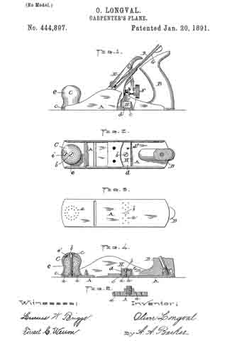
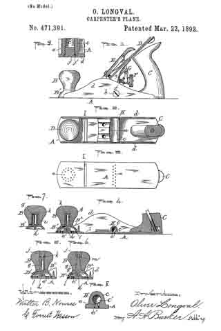
Figure 1 represents a side view of a carpenter’s plane embodying my improvements. Fig. 2 is a horizontal section through the handle, showing a top or plan view of the plane with the knife and the usual holding parts thereof detached to more fully illustrate that part of my improvements coming under the same. Fig. 3 is a bottom view of the plane. Fig. 4. is a vertical longitudinal section through the parts shown in Fig. 2. Figs. 5, 6, and 7 represent different modifications in the construction of the front oiler of the plane, which will be hereinafter more fully described. Fig. 8 is a vertical section of the rear oiler and part of the bed of the plane, taken on line a, Fig. 2; and Fig. 9 is an enlarged horizontal section through part of the plane-bed and one end of said rear oiler, showing the inlet to the oil-chamber and its detachable stopper or plug, taken on line 19, Fig. 1.
With the exception of the oiling devices hereinafter described, the plane is of ordinary construction.
The purpose of my invention is to improve upon the means heretofore employed for oiling the bottom of the plane; and it consists in certain improvements in the construction of said oiling devices foreffecting the above result.
In order that others may better understand the nature and purpose of said improvements, I will now proceed to describe the same more in detail.
In the drawings, A represents the bed, B the front handle, C the rear handle, D the knife or blade, E the knife-holding cap, F the adjusting-screw, and G the lever, of an ordinary plane. The rear oiling device H is preferably located on the bed between the base of handle C and the knife and its supporting parts. It is constructed by forming a transverse rib or projection c on the top of and integral with the bed between the vertical side flanges d d thereof. Within said transverse projection is formed a chamber c’ for holding the oil, which chamber is provided with an opening at one end through which to pour in the oil and with a series of small vertical openings e, through which said oil is discharged to oil the bottom of that portion of the plane coming back of the throat I. The inlet to chamber c’ is provided with a suitable screw or plug f and washer f’ to prevent the oil from passing out at said point, while the small vertical discharge-openings are provided with wood plugs e’, preferably of pine or similar soft porous wood, to properly control the outflow of oil.
Said wood plugs I find in practice permit just sufficient oil to pass out to oil the bottom of the plane properly and without waste of oil, the plane when thus oiled running smooth and easy upon the most objectionable surfaces. The essential feature which I claim as new in this part of my invention is the formation of the oiler integral with the bottom or bed of the plane and providing the chamber with an end opening and plug, so that the chamber may be more conveniently opened from the outside of the plane, as shown, in filling the same.
The use of wood plugs in the discharge-openings I am aware is not new, the same being shown and claimed in the United States Patent to Edward F. Gordon, No. 213,104, dated March 11, 1879, and I therefore make no claim, broadly, thereto.
The front handle B constitutes a part of the oiling device for oiling the front end of the plane, and said device is constructed as follows: A metal base B’, made in the form of an inverted cup, so as to form a chamber B2 between the same and the bed when fitted in position, is provided with a vertical central stem g, projecting up, and over which is fitted the knob or handle B. A downwardly-projecting central screw h is also formed on the base, which is adapted to be screwed into a correspondingly-shaped vertical opening formed in the bed, whereby the base is fastened to said bed. The stem g may be made with a threaded surface, so that the knob B may be screwed on, as shown in Fig. 4, or smooth, so that said knob may be driven on, as shown in Figs. 5 and 6.
The oil is preferably supplied to chamber B2 through an opening formed vertically through the stem g and connecting with said chamber through suitable openings at each side of the screw h, as is shown in Figs. 4 and 5. I do not limit myself, however, to forming the oil-inlet in the stem g as aforesaid, as a like result may be effected by means of a plugged inlet, as g’, in the body of base B’, as is shown in Fig. 6.
In case a wood knob or handle B is used, it is preferable to employ an internally-threaded tube i in the opening which receives the stem g to produce a more durable construction, as is shown in Fig. 7.
In the constructions shown in Figs. 4 and 7 the handle or knob serves as the stopper for preventing the oil from passing out through the supply-opening, while in Fig. 5 a screw-plug or nut j is employed for that purpose, a screw being formed on the plug, which may be screwed into the oil-inlet, which is threaded at its upper end for the purpose. In Fig. 6 a reverse construction is adopted, a threaded opening being formed in the plug to receive a screw formed at the upper or outer end of the stem; but said stem does not in this instance serve as an oil-passage, the nut j being used for holding the knob B in place. In each case an elastic or other suitable washer k is preferably used at the oil-inlet under the knob or plug to make the same oil-tight, and a suitable washer l is also used for the same purpose between the base B’ and bed A. In like manner to the other oiler, a series of vertical discharge-openings are formed in said bed for the front oiler last described, formed within the circumference of the bearing-point of the base against the bed, which openings are also provided with wood plugs e’, as in the former instance.
My improvement in the front oiling device consists in the combination of the separate and detachable knob B and base B’ and the special construction adopted in connection therewith and the plane-bed for effecting the desired result.
I am aware of the United States Patents to W. Wood, No. 191,393, dated May 29, 1877, and 471,391 to L. A. Dearth, No. 363,213, dated May 17, 1887, both for planes, and I make no claim to the constructions therein set forth and shown.
What I claim as new, and desire to secure by Letters Patent, is —
1. In a carpenter’s plane, the bed having a transverse chamber c’ formed therein open at the end having a series of vertical openings or outlets through the bed to the bottom of the plane, in combination with a suitable plug or stopper having a washer under the same for closing the aforesaid end opening and wood plugs for closing the vertical openings, while at the same time permitting a certain quantity of oil to discharge through the latter, substantially as and for the purpose set forth.
2. In a carpenter’s plane, the bed having a series of vertical openings in its front end filled with wood plugs, as described, in combination with the base B’, made cup-shaped to form an oil-tight chamber between the same and the bed when fitted thereto, with a washer between it and said bed, also having a downwardly-projecting screw part for securing said base to the bed and an upwardly-projecting stem fitting in a knob or handle B, said knob or handle, and means for supplying oil to the chamber in the base, as well as for closing the supply-opening thereto oil-tight, substantially as and for the purpose set forth.
3. In a carpenter’s plane, the bed having a series of vertical openings in its front end filled with wood plugs, as described, in combination with the base B’, made cup~shaped to form an oil-tight chamber between the same and the bed when fitted thereto, with a washer between it and said bed, also having a downwardly-projecting screw part for securing said base to the bed and an upwardly-projecting stem having a threaded tube or sleeve over the same, as well as having a vertical opening therein connected with the chamber in base B’ and fitting in the knob or handle B, said knob or handle, and a washer interposed between the same and the end of the stem, substantially as and for the purpose set forth.
OLIVER LONGVAL.
Witnesses:
ALBERT A. BARKER,
W. B. NOURSE.


