No. 984,083 – Floor-Plane (William J. Faber) (1911)

UNITED STATES PATENT OFFICE.
_________________
WILLIAM J. FABER, OF ONEIDA, NEW YORK.
FLOOR-PLANE.
_________________
984,083. Specification of Letters Patent. Patented Feb. 14, 1911.
Application filed March 28, 1910. Serial No. 551,829.
_________________
To all whom it may concern:
Be it known that I, WILLIAM J. FABER, of Oneida, in the county of Madison, in the State of New York, have invented new and useful Improvements in Floor-Planes, of which the following, taken in connection with the accompanying drawings, is a full, clear, and exact description.
This invention relates to certain improvements in floor planes for smoothing floors and other wood surfaces.
ln the use of ordinary planes the cutting blade is previously set or adjusted to produce the desired depth of cut and remains in this position until readjusted to vary the depth of the cut and under such conditions, preferably in smoothing the surface of hard wood, it is extremely difficult to start the plane on its initial movement owing to the fact that immediately upon the beginning of such movement the cutting edge is embedded to the full depth of its adjustment into the wood, thereby requiring considerable power to move the plane forward. Furthermore under the same conditions when the plane is drawn backward, the cutting edge is allowed to drag or ride over the surface of the floor, thereby producing excessive wear and more or less dulling effect upon such edge, and making it necessary to frequently regrind or re-sharpen the same.
The main object of my present invention is to provide means whereby the cutting edge of the blade will be held clear of the surface of the floor during the initial forward movement and will be gradually forced to its cutting position as the plane advances, thereby enabling the operator to move the plane forwardly under comparatively light pressure or force or until under sufficient momentum to permit the plane to be carried to the limit of its forward stroke with a minimum amount of power. In other words, the object sought is to cause the cutting edge of the blade to automatically clear the surface of the floor during the backward stroke and to be gradually moved to its cutting position during the forward stroke, so as to allow the plane to be moved through the complete forward stroke with a minimum degree of power and at the same time relieving the cutting edge from undue wear during the backward stroke.
Other objects and uses relating to specific parts of the device will be brought out in the following description.
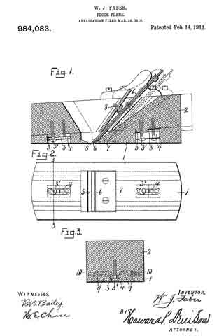
In the drawings: Figure 1 is longitudinal sectional view of a plane embodying the various features of my invention. Fig. 2 is an inverted plan of the same. Fig. 3 is a transverse sectional view taken on line 3-3-, Fig. 2.
This plane comprises a base section –1– and a stop section –2– resting upon and movable relatively to the base section. The meeting faces of said sections are inclined rearwardly from the front end and are therefore disposed at an angle with the bottom of the base section –1– which is substantially flat. The object of the inclined meeting faces is to permit a slight vertical movement of the section –2– as the plane is moved forward and backward. The upper section –2– is adapted to be engaged by the hand of the operator and it therefore follows that during the operation of moving the plane forward the upper section will be moved down the incline or slightly lowered, while the backward movement will similarly elevate the top section. These sections –1– and –2– are limited in their relative endwise movement by suitable stops –3– consisting in this instance of bosses which are projected into elongated slots –4– near the front and rear ends respectively of the base section –1– and formed with threaded apertures in the under side of the top section –2–. The slots –4– are enlarged at the bottom to receive the heads of screws –3’– and to form shoulders against which said heads abut to hold the meeting faces of the sections –1– and –2– in sliding contact, the heads of the screws being wholly within the lower surface of the section –1– to prevent contact with the surface which is being planed. This lower section –1– is also provided with a comparatively narrow knife opening –5– through which the cutting edge of a knife blade, as –6–, is movable and adapted to protrude when in operative position, the lower surface of the section –1– just back of the cutting blade being reinforced by a metal plate –7–. The cutting blade –6– is adjustably mounted in and upon the upper section –2– where it is locked or held in its adjusted position by a set screw –8– or other suitable fastening means, not necessary to further illustrate or describe, it being understood that any well known fastening means common in this art may be employed for this purpose which will enable the blade to be adjusted so that its cutting edge protrudes more or lesss through the opening –5–.
The plane is operated back and forth by the engagement of one or both hands of the operator upon the upper section –2– and owing to the fact that this section is movable relatively to the lower section –1– it is apparent that as the plane is drawn back the upper section will be moved up the incline of the lower section a distance corresponding to the length of the slots –4– or until limited by the engagement of the limiting stops with the rear ends of the slots thereby elevating the cutting edge of the blade –6– above the lower face of the plane section –1– whereupon the continued backward movement of the upper section of the plane effects a corresponding backward movement of the lower section –1–, as soon as the limiting stops –3– engage the rear ends of the slots –4–, it being understood that when the cutting blade is in its lowermost position the protrusion of its cutting edge will not exceed the degree of rise of the incline for the length of the slot. In moving the plane forward for the cutting operation assuming that the upper section is then in its extreme backward position or at the highest point of incline, the upper section will be initially or first moved down the incline and relatively to the lower section until the cutting edge of the blade is brought into engagement with the surface to be planed or until the limiting stops –3– engage the front ends of the slots –4– whereupon both sections will be moved forwardly together. This initial movement of the upper section –2– relatively to the lower section –1– requires but little strength or force and enables the operator to get the plane under head-way or momentum before the cutting edge of the blade is embedded to its maximum degree of adjustment into the wood and therefore this momentum aids the operator in forcing the plane through its forward stroke during the cutting operation, thereby reducing the power required to operate the plane from one extreme to the other of its cutting stroke. Another advantage is that when the plane is drawn back by means of the upper section –2– which rides upwardly along the incline of the lower section, the blade is withdrawn from the face of the lower section thereby avoiding excessive wear or rounding of the cutting edge.
In order that the section –2– may be guided longitudinally of and parallel with the lower section –1–, I provide the meeting faces of said sections with one or more tongues –9– and corresponding grooves –10– interfitting with each other, although the limiting stops –3– playing in the grooves –4– perform a similar function.
The operation of my invention will now be readily understood upon reference to the foregoing description and accompanying drawings and though I have shown a specific mechanism for adjusting and clamping the cutting blade and specific form of stops for limiting the relative endwise movement of the plane sections, I do not wish to limit myself to any particular form of construction of either one of these mechanisms, nor to the exact means for moving the cutting blade into and out of the opening –5– or above or below the lower face of the lower section, further than it must be some means whereby the blade is elevated on the backward movement of the upper section and lowered to its cutting position upon the forward movement of the same section.
What I claim is:
1. In a hand operated plane, two frame sections mounted one upon the other and having their meeting faces inclined longitudinally from front to rear, a cutting blade adjustably mounted on the upper section and having its lower edge protruding through the bottom of the lower section when in its cutting position, the upper section being movable endwise relatively to the lower section whereby the cutting blade is raised and lowered as the upper section is moved backward and forward, and means for limiting such movement.
2. In a floor plane, two frame sections mounted one upon the other, the upper face of the lower section being inclined from front to rear and the upper section resting upon and movable along said inclined face, a cutting blade mounted upon the upper section and protruding through the bottom of the lower section when in its cutting position, and means for limiting the movement of the upper section relatively to the lower section.
3. In a floor plane, two frame sections mounted one upon the other and having inclined meeting faces in sliding contact, a cutting blade adjustably mounted upon the upper section and having its cutting edge movable to and from a position below the bottom face of the lower section as the upper section is moved forward and backward, and means for limiting such movement.
In witness whereof I have hereunto set my hand on this 19th day of March 1910.
WILLIAM J. FABER.
Witnesses:
HARRY H. JACOBS,
JAMES E. BREWER.


