No. 1,291,856 – Plane (Louis Haneberg) (1919)

[paiddownloads id=”722″]1291856


UNITED STATES PATENT OFFICE.

_________________

LOUIS HANEBERG, OF BULLRUN, OREGON.

PLANE.

_________________

1,291,856. Specification of Letters Patent. Patented Jan. 21, 1919.
Application filed May 4, 1918. Serial No. 232,617.

_________________

To all whom it may concern:

Be it known that I, LOUIS HANEBERG, a citizen of the United States, residing at Bullrun, in the county of Clackamas and State of Oregon, have invented new and useful Improvements in Planes, of which the following is a specification.

This invention relates to improvements in planes for use by carpenters and other workers in wood and especially with reference to the provision of a tool of this character which may be adjusted or modified in size and thereby adapted for use either as a smoothing plane, a jack-plane or a jointer-plane, as may be desired.

The invention consists in the construction, combination and arrangement of devices hereinafter described and claimed.

In the accompanying drawings:–

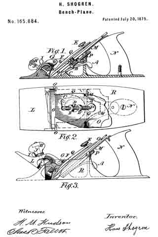
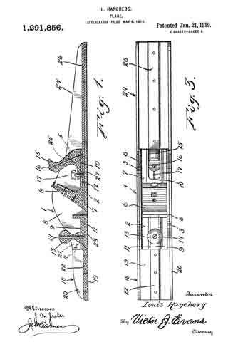
Figure 1 is a vertical longitudinal sectional view of a plane constructed in accordance with my invention, and showing the same arranged for use as a jointer-plane.

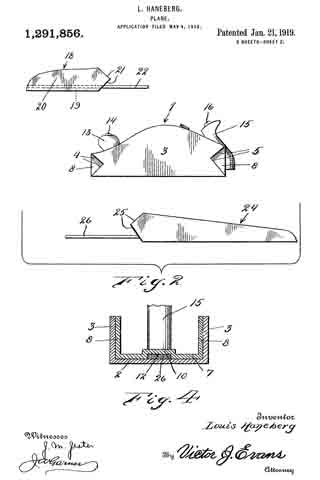
Fig. 2 is an elevation of the same, with the parts disconnected from one another.

Fig. 3 is a plan of the same.

Fig. 4 is a vertical transverse sectional view of the same.

My improved plane comprises a central member or body 1, which is made of iron or steel and comprises a shoe or bottom 2 and side walls or flanges 3. Said walls or flanges are provided in their ends with V-shaped dovetail notches 4, 5 which are reversely arranged as shown, and are respectively at the front and rear ends of the member 1. The frog 6 on which the usual bit is placed is also made of metal and is integral with a plate which bears on the bottom 2 and is formed with side flanges or walls 8 which are secured to the inner sides of the side walls 3 and are co-extensive therewith so that the said flanges or walls 8 form bottoms for the dovetail notches. The central portion of the plate 7 is formed with longitudinally arranged offsets 9, 10 which form slots 11, 12 which extend respectively to the front and rear ends of the member 1. The usual knob 13 is secured on the offset 9 by a screw 14, the lower end of which is conical in form. The usual handle 15 is secured on the oJi`set 10 by a screw 16 and also by a set-screw 17, the lower end of the set-screw being conical.

The body 1 when equipped with a suitable bit forms a smoothing plane.

An extension 18 is provided for the front end of the plane and to form a jack-plane when said extension is attached to the front end of the body 1. The said extension is made of iron or steel and comprises a bottom or shoe 19 and side walls or flanges 20, the rear ends of which are V-shaped as at 21, to form dovetail tongues which are adapted to closely fit in the dovetail notches 4. In the bottom of the extension 18 is a connecting plate 22 which is secured thereto and the rear ortion of which extends rearwardly therefrom and is adapted to enter the slot 11 and is provided with an inverted conical opening 23 for engagement by the lower end of the screw 14 so that the screw serves to firmly draw and clamp the extension 18 against the rear end of the body or member 1 as well as to secure the knob 13 in place.

When the extension 18 is thus secured to the rear end of the member 1 the plane is arranged for use as a jack-plane, as will be understood.

I also provide a rear extension 24 which is similar in construction to the construction 18 and the side walls of which are provided at their front ends with V-shaped tongues 25 to enter the notches 5. The connecting plate 26 of the extension 24 projects at its front portion from the front end of said extension and is adapted to enter the slot 12 and has a conical opening 27 with which the conical lower end of the set-screw 17 engages so that said set-screw serves to closely draw and clamp said extension 24 to the rear end of the member 1.

When the extension 24 is thus secured the plane forms a jointer-plane.

Owing to the provision of the side walls 8 of the frog member 6 and which cover the inner sides of the dovetail notches the dove-tail projections or tongues of the front and rear extensions bear directly against said walls or flanges 8 and lateral displacement of the extensions 18 and 24 is absolutely prevented so that the side walls of the main member 1 and the extensions 18 and 24 all lie in exactly the same planes and present unobstructed smooth outer surfaces, adapting the plane for use on fine work.

While I have herein shown and described a preferred form of my invention, I would have it understood that changes may be made in the form, proportion and construction of the several parts, without departing from the spirit of my invention and within the scope of the appended claims.

Having thus described my invention, I claim :–

1. In a plane, a main member having a longitudinally arranged slot, an extension member having a connecting plate projecting therefrom and arranged to enter the slot, a handle on the main member and a screw securing the handle to the main member and also securing the plate in the slot.

2. In a plane, a main member having a longitudinally arranged slot, an extension member having a connecting plate projecting therefrom and arranged to enter the slot, a handle on the main member and a screw securing the handle to the main member and also securing the plate in the slot, said plate having a conical opening and the screw having a conical point to engage in said opening.

3. In a plane, a main member having side walls provided with notches at the ends, said main member being also provided with a frog member having side walls which form the inner sides or bottoms of said notches, extension members for the plane having side walls provided with projections to enter said notches and means to detachably secure said extension members.

4. In a plane, a main member, a frog member in the main member and provided with a bottom portion having an offset forming a longitudinal slot, and an extension member having a plate projecting therefrom and arranged to engage in said slot.

In testimony whereof I affix my signature.

LOUIS HANEBERG.

_________________

Copies of this patent may be obtained for five cents each, by addressing the “Commissioner of Patents, Washington, D. C.”
_________________

No. 398,247 – Plane (Henry Fry) (1889)

[paiddownloads id=”445″]398247


UNITED STATES PATENT OFFICE.

_________________

HENRY FRY, OF EUGENE CITY, OREGON.

PLANE.

_________________

SPECIFICATION forming part of Letters Patent No. 398,247, dated February 19, 1889.
Application filed September 13, 1888. Serial No. 285,311. (No model.)

_________________

To all whom it may concern:

Be it known that I, HENRY FRY, a citizen of the United States of America, residing at Eugene City, in the county of Lane and State of Oregon, have invented certain new and useful Improvements in Planes; and I do hereby declare the following to be a full, clear, and exact description of the invention, such as will enable others skilled in the art to which it appertains to make and use the same, reference being had to the accompanying drawings, and to letters or figures of reference marked thereon, which form a part of this specification.

My invention relates to improvements in carpenters’ planes; and it consists in the novel construction and combination of the parts thereof, as will be more fully hereinafter described and claimed.

The object of my invention is to construct a plane wherein the depth of cut of the bit may be adjusted while the plane is in motion without readjusting the bit after the initial setting thereof. I attain this object by the construction illustrated in the accompanying drawings, wherein like letters of reference are used to designate similar parts in the several views, and in which —

Figure 1 is a sectional elevation of a plane, showing my improved construction in connection therewith. Fig. 2 is a detail perspective view of the bit-guard.

S indicates the stock, having the handle s, bit aperture or well s’, and bit and wedge W, all of which are well known in the art.

The improvement consists in securely hinging to the back end of the stock S a movable shoe or bottom, B. To the forward part of the shoe B a stationary flanged socket-nut, E, is secured, the screw-threaded socket thereof projecting upward into and movable in a recess formed in the stock S. An elongated rod, A, having a lower screw-threaded end to engage the screw-threaded socket of nut E and a top projecting knob for engagement by the operator passes through an aperture in the plane-stock. The said rod A immediately under the top knob is provided with a collar, a; and over this collar and fitted into the top surface of the stock is a plate or plates for holding the said collar and screw-rod down and preventing the same rising from the stock.

To prevent the bit from springing backward when striking knots or when cutting deep in hard wood, due to its extended projection from the bottom of the stock to accommodate the improved construction, I provide a guard-casting, F, which is secured to the bottom of the stock adjacent to the bit-end. This guard consists of a horizontal plate, f having screw-holes therein, and an obliquely-arranged plate, f’, integrally formed with its forward end. The oblique plate f’ has its lower edge beveled, and the greater part thereof projects below plate f. When this guard is adjusted in position, the plate f’ thereof bears against the lower end of the bit and prevents the same from springing backward. The part of plate f’ above plate f sinks into the wood or metal of the stock and firmly re-enforces the guard at this point.

The shoe B, working on the hinge and adjusted by the screw-rod A, virtually raises and lowers the plane-bit from and toward the surface planed, causing it to out a light or heavy shaving at the will of the operator, and the adjustment set forth may be readily attained while the plane is in motion, thereby saving the time and labor involved in setting the bits of planes now in use.

In using an iron plane-stock with a wooden shoe, B, two bosses or lugs cast with the back end of the stock would make the hinging of said shoe practicable, and the screw-rod A would then work through the iron stock.

Having thus described my invention, I claim —

1. In a plane,the combination, with a stock having a bit-well therein, of an elongated shoe hinged thereto and solid throughout with the exception of a slot therein for the passage of the bit therethrough, a screw-rod for adjusting said shoe, and a casting composed of a horizontal member secured to the bottom of the stock adjacent to the bit-well, and a front integral member arranged at an angle to said horizontal member, and against which the bit has bearing at its lower end, substantially as described.

2. A plane comprising a, stock with at bit-well, an elongated shoe hinged to the rear end of the stock and having a flanged set-nut secured therein near the front end, a revoluble screw-rod in the stock engaging the set-nut, and a casting, F, having a horizontal member, f, secured to the bottom of the stock, and integral oblique member f’, bearing against the lower end of the bit, substantially as described.

In testimony whereof I aflix my signature in presence of two witnesses.

HENRY FRY.

Witnesses:
W. R. McCORMACK,
JOEL WARE.

No. 165,884 – Improvement In Bench-Planes (Hans Shogren) (1875)

[paiddownloads id=”249″]165884


UNITED STATES PATENT OFFICE.

_________________

HANS SHOGREN, OF PORTLAND, OREGON.

IMPROVEMENT IN BENCH-PLANES.

_________________

Specification forming part of Letters Patent No. 165,884, dated July 20, 1875; application filed March 19, 1875.

_________________

To all whom it may concern:

Be it known that I, HANS SHOGREN, of Portland, Oregon, and in the county of Multnomah of said State, have invented an Improvement in Bench-Planes, of which the following is a specification:

In the drawings, Figure 1 is a longitudinal section through or near the center. Fig. 2 is an inverted plan, looking upward from the bottom. Fig. 3 is a side elevation, partly in section, showing the movable front.

The nature and object of my invention are as follows: In many kinds of work it is necessary to bring the plane-bit O close against a glue-joint or projecting part of a rabbet, or other angular part rising above the surface to be planed, and with common planes this cannot be done, on account of the fore part of the plane in front of the bit, and after planing with them the end can only be finished with a chisel; but by the arrangement herein shown the work may be fully done by the plane itself. To accomplish this the fore part L of the plane R is hung on two screw-centers, G, situated one on either side of the plane opposite the opening for the shavings; and this part L is further provided with a knob, H, in which the nut and screw J are placed, and between H and L a small thumb wrench, I, is placed. The head of the screw J is a sort of eccentric or hook-shape, the sides of the screw-shaft being flattened in such manner that they ht the opening in the center of the wrench I.

Fig. 1 shows the plane when used as a common plane; and Fig. 2 shows the piece L closed in its place in front of the cross-rib K, which is a part of the back portion ofthe plane R. The head of the screw J is hooked. To change this, and put it in the position shown in Fig. 3, the following operation is gone through: First, the knob H, which carries the nut of the screw J, is turned so as to unscrew the nut, and while holding the knob H between the thumb and finger of one hand the other thumb turns the wrench I in such way as to still further unscrew the screw J, and this latter operation turns the screw half round, and disengages it from the cross-rib K. It may now be opened freely, as in the Fig. 3, or thrown entirely back on the top of the plane-iron, and in this position it may be used as now described. By looking at Fig. 2, and at the chip-opening in front of the bit O, an oblique line is seen crossing the under surface of the plane, and at its narrow end to run into the chip-opening. This is the joint between the front part L and the back part of the plane, so that if L were raised up or opened, as in Fig. 3, a portion of the chipway would be entirely open at the front, and half or more would have a narrow bearing in front of the plane-bit. In planing up to a projection this is so arranged that this part prevents the wood from lifting in front of the bit, and having planed to within a quarter of an inch or less of the object the plane is pushed sidewise, and in this way the chip is cut entirely out by the exposed part of the bit, the joint being so arranged that the bit is the foremost object on that side of the plane.

The next feature is the manner of fastening the bit O by means of the forked clamp Q, Fig. 2, screw E, and two pins, F, on theinside of the chip-opening, one on either side, so that the forked clamp Q passes under them somewhat after the manner of the wedge in a wooden plane, and to facilitate keeping Q in its place little hollows are formed on its upper surface, so that they will slightly engage with the pins F, and being so set under the pins F the screw E is tightened, and in this way the bit O is held firmly against its seat in the metal part R. The bit O is like those used in a common wood-plane, having at its back or under side the head of the clamp-screw D.

An arrangement for setting the bit O is as follows: A thumb-lever, A, projecting into the finger-opening in front of the handle N turning on a center, O, Fig. 2, carries a pitman-screw, P, in a joint of its shorter bent end. On the screw P are two nuts, B B’, which turn freely up or down, and are adjustable on the head of the clamp-screw D, and, being in proper adjustment, any movement of A raises the bit up or down. The center G is attached to the bottom of the plane, on the upper side, and beneath the bit O. A forked metal piece, M, Fig. 2, is fastened to the upper part of the handle N by a screw, and the corners or ends of the same to the metal part of the plane near the upper bearings for the bit O, and between these two bearings a vertical web (a bent part of this same piece M) extends, through which a hole is made forming the upper support for the screw P, and all together forming a firm support for the handle N. The whole plane is made of iron or other metal, except the handle N and knob H, which are of wood. The joint between the front and back part is neatly fitted, and the bottom is planed up neat and straight.

I claim —

A bench-plane, provided with the adjustable hinged part L, substantially as and for the purpose specified.

HANS SHOGREN.

Witnesses:
H. M. HUDSON,
CHAS. B. TALBOT.