No. 781,771 – Plane (William H. Gardner, Jr.) (1905)
UNITED STATES PATENT OFFICE.
_________________
WIILLIAM H. GARDNER, JR., OF PARK CITY, UTAH.
PLANE.
_________________
SPECIFICATION forming part of Letters Patent No. 781,771, dated February 7, 1905.
Application filed April 21, 1904. Serial No. 204,268.
_________________
To all whom it may concern:
Be it known that I, WILLIAM H. GARDNER, Jr., a citizen of the United States, residing at Park City, in the county of Summit and State of Utah, have invented certain new and useful Improvements in Planes; and I do declare the following to be a full, clear, and exact description of the invention, such as will enable others skilled in the art to which it appertains to make end use the same.
This invention relates to improvements in planes, and particularly to the class of rabbeting-planes.
The object of the invention is to provide a plane of this character having means whereby the handle may be adjusted to one side to permit the plane to be used close up against a shoulder without danger of striking the knuckles of the operator.
Another object is to provide means whereby the plane is prevented from becoming clogged with shavings.
With this and other objects in view the invention consists of certain novel features of construction, combination, and arrangement of parts, as will be more fully described, and particularly pointed out in the appended claims.
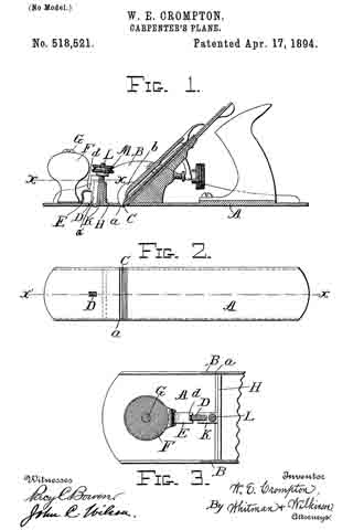
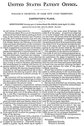
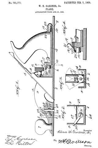
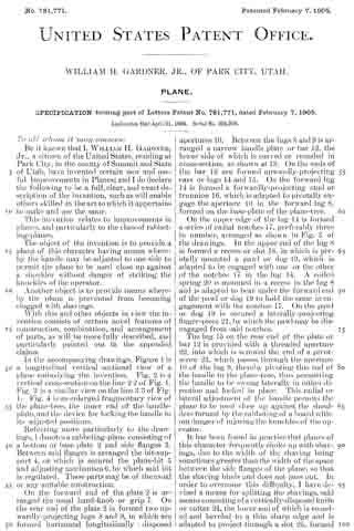
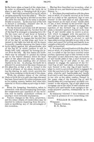
In the accompanying drawings, Figure 1 is a longitudinal vertical sectional view of a plane embodying the invention. Fig. 2 is a vertical cross-section on the line 2 2 of Fig. 1. Fig. 3 is a similar view on line 3 3 of Fig 1. Fig 4 is an enlarged fragmentary view of the plane-tree, the inner end of the handle-plate, and the device for locking the handle in its adjusted positions.
Referring more particularly to the drawings, 1 denotes a rabbeting-plane consisting of a bottom or base plate 2 and side flanges 3. Between said flanges is arranged the bit-support 4, on which is secured the plane-bit 5 and adjusting mechanism 6, by which said bit is regulated. These parts may be of the usual or any suitable construction.
On the forward end of the plate 2 is arranged the usual hand-knob or grip 7. On the rear end of the plate 2 is formed two upwardly-projecting lugs 8 and 9, in which are formed horizontal longitudinally-disposed apertures 10. Between the lugs 8 and 9 is arranged a narrow handle plate or bar 12, the lower side of which is curved or rounded in cross-section, as shown at 13. On the ends of the bar 12 are formed upwardly-projectingg ears or lugs 14 and 15. On the forward lug 14 is formed a forwardly-projecting stud or trunnion 16, which is adapted to pivotally engage the aperture 10 in the forward Iug 8, formed on the base-plate of the plane-tree.
On the upper edge of the lug 14 is formed a series of radial notches 17, preferably three in number, arranged as shown in Fig. 3 of the drawings. In the upper end of the lug 8 is formed a recess or slot 18, in which is pivotally mounted a pawl or dog 19, which is adapted to be engaged with one or the other of the notches 17 in the lug 14. A coiled spring 20 is mounted in a recess in the Iug 8 and is adapted to bear under the forward end of the pawl or dog 19 to hold the same in engagement with the notches 17. On the pawl or dog 19 is secured a laterally-projecting finger-piece 21, by which the pawl may be disengaged from said notches.
The lug 15 on the rear end of the plate or bar 12 is provided with a threaded aperture 22, into which is screwed the end of a pivot-screw 23, which passes through the apperture 10 of the lug 9, thereby pivoting this end of the handle to the plane-tree, thus permitting the handle to be swung laterally in either direction and locked in plaice. This radial or lateral adjustment of the handle permits the plane to be used close up against the shoulders formed by the rabbeting of a board without danger of injuring the knuckles of the operator.
It has been found in practice that planes of this character frequently choke up with shaings, due to the width of the shaving being sometimes greater than the width of the space between the side flages of the plane, so that the shaving binds and does not pass out. In order to overcome this difficulty I have devised a means for splitting the shavings, said means consisting of a vertically-disposed knife or cutter 24, the lower end of which is rounded end beveled to a thin sharp edge and is adapted to project through a slot 25, formed in the lower plate or base 2 of the plane-tree. ln order to adjustably hold the knife 24 in place in said slot, a clamping-bolt 26 is provided. Said bolt is mounted in a lug 27, which projects upwardly from the plate 2. The forward side of the lug has a beveled or cam face 28, while the rear face of the same is perpendicular or square. In the rear end of the bolt is formed a vertically-disposed slot 29, in which the knife 24 is disposed.
On the forward end of the bolt 26 between the head of the same and the beveled face 28 of the lug 27 is arranged a clamping-lever 30. On the inner end of said lever is formed a head 31, having a beveled or cam face 32, which is adapted to engage the beveled face 28 of the lug 27, so that when said lever is turned to the right the bolt 26 will be drawn forwardly, thereby clamping the blade of the knife tightly against the perpendicular side of the lug 27, in which position it will be firmly held until released by turning the lever 30 to the left. By this means the knife-blade may be adjusted to project its cutting end to the desired distance below the base-plate of the plane-tree and then clamped in this position, thus enabling slits of various depths to be cut. ln planing, the knife 24 is adjusted to project about the same distance as the plane-bit, so that a slit is formed in the wood in advance of the plane, thereby causing the shaving to split, which prevents the same from wedging in the throat of the plane.
While the primary object of the cutting blade or knife 24 is to split shavings, the same has been found useful for other purposes, such as for cutting veneers, leather, and other thin material in which a clean square edge is desirable.
From the foregoing description, taken in connection with the accompanying drawings, the construction and operation of the invention will be readily understood without requiring a more extended explanation.
Various changes in the form, proportion, and the minor details of construction may be resorted to without departing from the principle or sacrificing any of the advantages of this invention.
Having thus described my invention, what I claim as new, and desire to secure by Letters Patent, is —
l. ln a plane, the combination with the plane tree or stock, of a handle secured at its lower end to a plate or bar, apertured lugs or ears formed on the base-plate of said plane-tree, lugs formed on the ends of said handle plate or bar, a stud formed on the forward lug of said plate or bar and adapted to engage the aperture of the forward lug of said base-plate, a threaded aperture formed in the rear lug of said handle-plate to receive a pivot-bolt which is engaged with the aperture in the rear lug of said base-plate, whereby said handle-plate and handle is pivoted to said base-plate to swing laterally to one side or the other, and apawl for holding said handle in an upright or laterally-adusted position, substantially as described.
2. In a plane, the combination with the plane tree or stock, of a handle secured at its lower end to a plate or bar having a rounded under surface, apertured lugs or ears formed on the base-plate of said plane-tree, lugs on the ends of said handle plate or bar, a stud formed on the forward lug of said plate or bar, and adapted to engage the aperture of the forward lug of said base-plate, a threaded aperture formed in the rear lug of said handle-plate to receive a pivot-bolt which is engaged with the aperture in the rear lug of said base-plate, whereby said handle-plate and handle is pivoted to said base-plate to swing laterally to one side or the other, notches formed in the upper edge of the forward lug of said handle-plate and a spring-pawl pivotally connected to the adjacent lug of said plane-tree to engage one or the other of said notches and thereby hold said handle in an upright, or laterally-adjusted position, substantially as described.
In testimony whereof I have hereunto set my hand in presence of two subscribing witnesses.
WILLIAM H. GARDNER, JR.
Witnesses:
THOMAS GIBBONS,
H. G. BATES.