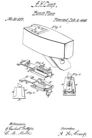
No. 180,050 – Improvement In Bench-Planes (William Montgomery) (1876)

[paiddownloads id=”265″]180050


UNITED STATES PATENT OFFICE.

_________________

WILLIAM MONTGOMERY, OF AMITY, PENNSYLVANIA.

IMPROVEMENT IN BENCH-PLANES.

_________________

Specification forming part of Letters Patent No. 180,050, dated July 18, 1876; application filed April 27, 1876.

_________________

To all whom it may concern:

Be it known that I, WILLIAM MONTGOMERY, of Amity, in the county of Washington and State of Pennstylvania, have invented Improvements in Bench-Planes; and I do hereby declare that the following is a full, clear, and exact description of the same, reference being had to the accompanying drawing, which forms part of this specification.

My invention relates to a new combination of devices for adjusting and clamping the blade or plane iron in the stock of the plane; and it consists in the combination of devices employed as hereinafter more fully set forth.

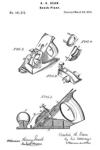
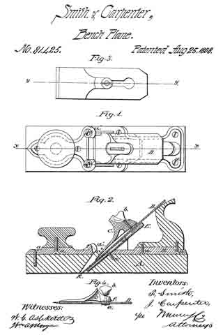
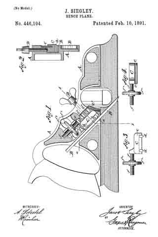
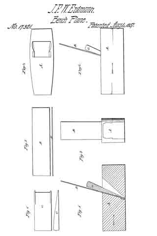
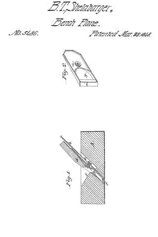
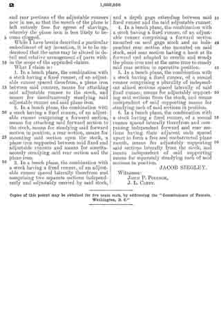
Figure 1 in the accompanying drawing, represents a vertical longitudinal section through my improved plane. Fig. 2 is a section through the plane irons and attachments thereof on the line x x. Fig. 3 is a top view of the bed-plate, to which the clamping-lever, which secures the irons in the plane-stock, is pivoted. Fig. 4 is a diagram illustrating the manner in which the grain of the wood runs in relation to the face of the plane.

A is the stock, which may be made of wood or metal. The said stock is thinner, measured vertically, at the rear end or heel than at the forward end, and at the rear end the stock is provided with a projection, p, which supports inpart the handle n. In cutting the plane-stock to the wedge form the grain of the wood is cut obliquely across, as shown in Fig. 4, in which the dotted lines represent the grain of the wood, and the line f f represents the face of the plane. The bed-plate B, shown in Fig. 3, and in section in Fig. 1, is attached to the top of the plane-stock A, at the back of the throat T of said stock, the attachment being made by screws x. The bed-plate B has at its front end lugs l, Fig. 3, to which is pivoted, by a screw-bolt, or in any other suitable manner, the bent lever L, the said bed-plate being cut away between the said lugs to make room for said lever L, and the tops of said lugs being rounded off, to allow the plane-irons i t to retreat far enough at the top to allow the insertion of a wedge under them at the bottom. The front part of the lever L passes down into the throat T of the plane, a recess, r, being formed in the back of said throat for the reception of the said front part of said lever, and the rear part of said lever passes backward over the top of the bed-plate, at the rear of the said throat T. In the rear part of said lever is fitted a thumb-screw, R, and in the front part of said lever is formed a dovetail-groove, g, shown in section in Fig. 2.

The head of the screw m, which holds the top iron on the cutting-iron of the plane, is made in the form of a frustum of a cone, and of dimensions to adapt it to the dovetail groove g in the front part of the lever L. The point of the thumb-screw R rests in a notched saddle, S, either on the handle h, the bed-plate B, or the plane-stock A, in various kinds of planes, and the said screw may fit a female screw in the rear end of the lever L, or it may fit the thread of a nut swiveled to the said lever. The half-handle h is formed in one piece with the bed-plate B, as shown in Fig. 1, when the plane-stock A is made of wood; but when the plane-stock is made of metal the bed-plate B may be dispensed with, and the lugs l of the same, and the handle h, may be cast in one piece with said stock. And when a jack-handle is used, it is attached to the stock, and not to the bed-plate B. Also, in long-faced planes the projection p, which supports the rear of the handle in short-faced planes, is omitted, there being space enough for the support of said handle without the projection. The cutting iron i and top iron t are fitted into the throat, as shown in Fig. 1, the top iron being held upon the cutting-iron by the screw m, which passes through the slot n, in the cutting-iron, and screws into the top iron in the usual manner.

The adjustment and clamping of the irons i and t are performed as follows: The top iron t is placed in its proper position on the cutting-iron i, and is fastened there by the screw m. The irons are then placed in the throat T of the stock A, the head of the screw in passing down into the groove g of the lever L. The screw R is then turned down, and, its point being prevented from advancing, the hinder part of the lever L is forced upward. This forces the lower part of the lever L downward and rearward, and draws backward and downward the screw m, the head of which is engaged in the groove g of the said lever, and the opposite end of which is engaged in the female screw of the top iron, t. The plane-irons are thus firmly pressed against the lower part of the throat of the plane-stock, and that part of the lever L in front of the pivot of said lever, which pressure securely clamps the irons in the plane-stock.

The head of the screw m might be made of proper form to engage a groove of rectangular cross-section in the lower part of the lever L; but I prefer the dovetail groove and the corresponding shape of head for the said screw, because this form gives a wedging action, which holds the irons powerfully without excessive strain on the thumb-screw R.

A cheap, easy-running, and durable plane is thus produced, in which the handle is brought down nearer the work than in planes heretofore used, and hence the muscular power of the operator is more efficiently applied.

I claim —

The combination of the stock A, having projection p, with the pivoted lever L, provided with a dovetail groove in its face, adjusting-screw R, notched saddle S, bed-plate and handle B h, and screw m, all constructed to operate as shown and described, and for the purpose specified.

WILLIAM MONTGOMERY.

Witnesses:
B. F. MONTGOMERY,
JAMES B. MONTGOMERY.

No. 161,213 – Improvement In Bench-Planes (Asahel H. Dean) (1875)

[paiddownloads id=”239″]161213


UNITED STATES PATENT OFFICE.

_________________

ASAHEL H. DEAN, OF PHILADELPHIA, PENNSYLVANIA.

IMPROVEMENT IN BENCH-PLANES.

_________________

Specification forming part of Letters Patent No. 161,213, dated March 23, 1875; application filed January 30, 1875.

_________________

To all whom it may concern:

Be it known that I, ASAHEL H. DEAN, of Philadelphia, Pennsylvania, have invented certain Improvements in Bench-Planes, of which the following is a specification:

The main object of my invention is to so construct a plane having a metal body or frame as to admit of the ready withdrawal, replacing, and adjustment of the plane-bit, and this object I attain in the manner which I will now proceed to describe, reference being had to the accompanying drawings, in which —

Figure 1 is a vertical section of my improved plane; Fig. 2, perspective view of the lever-clamp; Fig. 3, a perspective view of the plane; and Fig. 4, views illustrating part of my invention.

The body of the plane consists of the base A and two side pieces or cheeks, B and B’, the whole being, in the present instance, cast in one piece. The handle E of the plane and the knob F are secured to the base A by screws, in the manner shown in Fig. 1. The plane iron or bit C, which is of the usual construction, and has the usual cap plate h’, bears against a projection, j, of the wooden handle and against a shoulder, i, on the base, the cutting-edge of the bit projecting through a slot in the said base in the ordinary manner, and the bit being confined to its place by a lever-clamp, H, best observed in the perspective views, Figs. 2, 3, and 4. This clamp has on one side a segmental projection adapted to a circular opening in the cheek B, and on the opposite side a ring, f, adapted to a segmental groove, h, formed in the outer face of the cheek B. The projection e and ring f constitute the pivots or fulcrums of the lever-clamp, the upper end of which is caused to bear on the cap-plate by a set-screw, d, in a manner too clearly indicated by the drawing to need description, and to confine the bit to the shoulder on the base and the projection j of the handle.

After loosening the set~screw d, and thereby releasing from its bearings the lever-clamp H, the latter can be removed laterally, its projection e from the cheek B and its ring f from the segmental recess of the cheek B’, thereby permitting the plane-bit to be withdrawn, the clamp being as readily introduced into its place and secured after the adjustment of the plane-bit.

The bearing of the bit on the wooden handle E is an important feature of my invention, for the wood presents a surface to which the bit can be more firmly secured without danger of slipping, when the plane is subjected to accidental jars, than a metal surface.

I claim as my invention —

I. A plane in which the bit is confined to its bearings by a lever-clamp, H, constructed for connection to, and lateral withdrawal from, the frame or body of the plane, substantially in the manner described.

2. The clamp H, its set-screw d, projection e, and ring f, in combination with the cheek B, having an opening adapted to the said projection, and the cheek B, having a segmental recess adapted to the said ring, all substantially as set forth.

3. A plane having a metal body or frame, a wooden handle, and a retaining-screw, or its equivalent, between which and the handle the plane-bit is clamped, all substantially as described.

In testimony whereof I have signed my name to this specification in the presence of two subscribing witnesses.

ASAHEL H. DEAN.

Witnesses:
HUBERT HOWSON,
HARRY SMITH.

No. 102,630 – Improvement In Attaching Handles To Joiners’ Plows (Charles H. Weigle) (1870)

[paiddownloads id=”165″]102630


United States Patent Office.


CHARLES H. WEIGLE, OF YORK, PENNSYLVANIA.

Letters Patent No. 102,630, dated May 3, 1870.
_________________

IMPROVEMENT IN ATTACHING HANDLES TO JOINERS’ PLOWS.

_________________

The Schedule referred to in these Letters Patent and making part of the same.

_________________

To all whom it may concern:

Be it known that I, CHARLES H. WEIGLE, of York, in the county of York and State of Pennsylvania, have invented a new and useful Improvement in Removable Handles for Joiners’ Plows and Arm-Fillisters; and I do hereby declare that the following is a full, clear, and exact description thereof, which will enable others skilled in the art to make and use the same, reference being had to the accompanying drawings forming part of this specification, in which —

Figure 1 represents a side view of my invention, partly in section.
Figure 2 is a horizontal section of the same, taken in the line x x, fig. 1.

Similar letters of reference indicate like parts.

This invention relates to a new and useful mode of applying handles to joiners’ plows and arm-fillisters, whereby said implements may be used with a handle, and with far greater facility than hitherto, the handle being readily detached when the tool is not required ibr use, and is to be stowed away.

The invention consists in having a dovetail install-socket secured in the rear of the stock of the tool, and having the front edge of the handle provided with a dovetail metallic nib to fit into the socket, as hereinafter fully shown and described, whereby the desired end is attained.

A represents a portion of the stock of an ordinary joiners’ plane, and B is a metallic dovetail socket, which is let in the rear end of the stock, and secured in position by screws a.

C represents a wooden handle, which is constructed similarly to a saw-handle, and has a metallic rib, D, secured to its front side, said rib having a dovetail at its front part to fit into the socket B.

By this means the handle may be readily fitted to the plow, and also readily detached therefrom.

One handle will answer for a number of different tools, if they are all provided with a socket, B; and, when a plow is not in use, the handle may be detached, and the former put away without monopolizing any more room than usual.

I am aware that a patent was issued to W. S. Loughbrongh, April 4, 1854, having a similar object in view, and I therefore disclaim as any part of my invention all features of construction found therein.

Having thus described my invention,

I claim as new and desire to secure by Letters Patent —

The metal dovetail socket B, secured by screws as in a recess in the rear end of the wooden stock A of the plane, and adapted to receive the rib D on the front edge of the handle C, all as shown and described.

CHAS. H. WEIGLE.

Witnesses:
WILLIAM DENULY,
JOHN B. WENTZ.

No. 86,851 – Improvement In Moulding-Plane (A.W. Maxwell) (1869)

[paiddownloads id=”149″]86851


United States Patent Office.


A. W. MAXWELL, OF MILTON, PENNSYLVANIA.

Letters Patent No. 86,851, dated February 9, 1869.
_________________

IMPROVEMENT IN MOULDING-PLANE.

_________________

The Schedule referred to in these Letters Patent and making part of the same..

_________________

To all whom it may concern:

Be it known that I, A. W. MAXWELL, of the borough of Milton, county of Northumberland, and State of Pennsylvania, have invented a new and useful tool for moulding Wood, which I call “A Reversible Hand Moulding-Plane;” and I do hereby declare that the following is a full, clear, and exact description of the construction and operation of the same, reference being had to the annexed drawings, making a part of this specification, in which —

Figure 1 is a view representing the bottom of the plane, and
Figure 2, the top.
Letter a represents the convex centrabearing.
b, the knife-end of the bit.
c, the screws by which the bit is fastened to the body of the plane.
d, the openings in the bit, through which the screws pass, by which the bit is fastened, and by which, when unfastened, the bit may slide up or down.
e, the bit.
f, the handles of the plane.
g, the throat, partially seen, of the plane, through which the shavings of the wood pass.

The bottom of the plane is convex, the degree of convexity being greater or less, in different planes, to suit the nature of the work expected to be done.

The “centre-bearing ” a, enables the workman to reverse the plane when he desires, as, for instance, to avoid planing against the grain of the wood, or to make a smooth finish at the end of the material; and consists of a convex ridge, or bearing, running transversely across the middle of the plane, dividing the bite longitudinally into two equal parts, the knives of both of which sections, the plane being reversed, make exactly the same impressions upon the wood.

The bit e is a double bit, the one half of which is the reversed duplicate of the other, and is fastened to the body of the plane by the screws c running through the openings d, so as to allow the bit e to be moved or adjusted at pleasure.

What I claim, and desire to secure by Letters Patent, is —

The moulding-tool herein shown and described, when all the parts are constructed and arranged to operate as represented, and for the purpose set forth.

A. W. MAXWELL.

Witnesses:
FRANKLIN BOUND,
M. YOENT.

No. 81,425 – Improvement In Planes (F. Smith And I. Carpenter) (1868)

[paiddownloads id=”141″]81425


United States Patent Office.


F. SMITH AND I. CARPENTER, OF LANCASTER, PENNSYLVANIA.

Letters Patent No. 81,425, dated August 25, 1868.
_________________

IMPROVEMENT IN PLANES.

_________________

The Schedule referred to in these Letters Patent and making part of the same.

_________________

TO ALL WHOM IT MAY CONCERN:

Be it known that we, F. SMITH and I. CARPENTER, of Lancaster, in the county of Lancaster, and State of Pennsylvania, have invented a new and useful Improvement in Joiners’ Planes; and we do hereby declare that the following is a full, clear, and exact description thereof, which will enable those skilled in the art to make and use the same, reference being had to the accompanying drawings, forming part of this specification.

The nature of our invention relates to improvements in joiners’ planes, whereby it is designed to render the stocks less liable to warp, to regulate the weight of the same, to provide for a more perfect delivery of the shaving, adjusting the some to be used as a single or a double plane, and adjusting the mouth, so as to govern the width of the same for the passage of the shaving.

And it consists in constructing the stock partly of iron, substituting, for the tapered notches of wooden stocks for holding the tightening-wedges, set-screws for holding the wedge, which is made of metal, and provided with an additional tightening-screw in its upper end, which works against the face ofthe plane-bit, or into a swivel-nut which slides in the slots of plane-bits, as ordinarily constructed, and providing a wooden wedge at the back side ofthe plane-bit, as will be more fully described on reference to the accompanying drawings, wherein —

Figure 1 represents a plan view of our improved plane.
Figure 2, a central section ofthe same on the line x x of fig. 1.
Figure 3, a plan view of a part of our improvement applied to plane-bits, having the ordinary slot in the same; and
Figure 4 a section on the line y y of fig. 3.

Similar letters of reference indicate corresponding parts.

A represents the wood part of the stock, and B the iron portion of the same, which are secured together by the screws d d.

The part B may-be made of cast iron, and of different thicknesses, as may be desired to govern the weight of the plane.

The handle and knob may be secured to the part B in suitable sockets provided for them by the screws d d.

The part B is provided with lugs, a1 a1, through which set-screws, a2 a2, are arranged to hold the cap.

C represents a metal cap or wedge, provided with a set-screw, b, by which it may be, if desired, raised at its upper end from the bit D.

The said cap is provided with a raised portion, C’, in advance of the set-screw b, which rises by a gentle curve from the wedge portion of the same, so as to prevent the shavings from clogging against the screw.

When a plane-bit is used without a slot, as in figs. 1 and 2, we use a set-screw arranged as therein shown, but to adapt our improved tightening-wedge to plane-bits of the old construction, having the slot for set-screws as ordinarily constructed, we attach, to the ends of the set-screws, swivel-nuts, e, having slots in two edges of the same, which admit it to slide within the slot in the plane-bit, by taking the edges of the bit forming the side walls of the slot in the latter into the slots in the nut, the nut being of the proper size to be admitted through the enlarged portion of the slot in the plane-bit.

E represents a wedge, which may be made of wood or metal, and arranged in the bottom of the mouth of the stock under the plane-bit, and held there by the set-screw e1 passing through a slot in the said wedge, whereby it may be adjusted within the mouth ofthe stock.

The face of the wedge next the plane-bit is provided with a recess, e2, to admit the nut e of the set-screw.

The under side of the upper end of the metallic wedge C is provided with a recess, f, (see fig. 4,) when the nut e is used.

By the use of our improved wedge, the same plane-bit may be used for a double or single bit.

When used as a single bit, it may be applied as shown in fig. 2, and when used as a double bit, the set-screws a2 may be withdrawn, so that the wedge may be moved down sufficiently near to the edge of the bit to serve the purpose of a double bit.

By adjusting the upper end of the wedge by a set-screw, b, the width of the mouth may be adjusted to suit the different requirements of different kinds of work, or of different kinds of wood, or may be made of uniform width from bottom to top.

The same may be also adjusted by the wedge E to some extent, but the more important function of the wedge E is to govern the width of the throat at the cutting-edge of the bit, as at k, as will be readily understood.

In adjusting the wedge to the bit, when constructed as shown in figs. 3 and 4, the lower end of the wedge is placed at the right position with reference to the cutting-edge of the bit, and the thumb-screw turned to the left until the upper end of the wedge is screwed tightly to the bit. They are then inserted in the stock, the set-screws a2 adjusted to their right positions, when the set-screw b is turned in the opposite direction, and the wedge forced out against the set-screws a2.

The metallic part, B, of our stock may be taken off from a worn-out wood stock, and readily applied to a new one, or old plane-stocks of ordinary construction may be readily fitted to be attached to it.

We claim as new, and desire to secure by Letters Patent —

1. The adjustable cap, provided with the guard in front of the set-screw b, substantially as and for the purpose described.

2. The set-screws a2 in the lugs a1, arranged to clamp upon the adjustable wedge C, as herein shown and described for the purpose specified.

F. SMITH,
I. CARPENTER.

Witnesses:
P. G. EBERMAN,
F. R. GRUGER.

No. 81,879 – Improvement In Planes (Alfred H. Comp) (1868)

[paiddownloads id=”143″]81879


UNITED STATES PATENT OFFICE.

_________________

ALFRED H. COMP, OF MOUNT JOY, PENNSYLVANIA.

IMPROVEMENT IN PLANES.

_________________

Specification forming part of Letters Patent No. 81,879, dated September 8, 1868.

_________________

To all whom it may concern:

Be it known that I, ALFRED H. COMP, of Mount Joy, in the county of Lancaster and State of Pennsylvania, have invented a new and Improved Device for Adjusting the Width of the Mouth in Smoothing and other Planes; and I do hereby declare that the following is a full, clear, and exact description of the construction and operation of the same, reference being had to the accompanying drawings, making a part of this specification, in which —

Figure 1 shows the application of my adjusting-plates to the bottom of an ordinary smoothing-plane. Fig. 2 shows the plates separated; Fig. 3. the same reversed; Fig. 4, both plates joined, showing the outer face; Fig. 5, the same, showing the inner face and rear-edge view.

The nature of my invention consists in the construction of a dovetailed plate, T-shaped, operated by a horizontal screw, and inserted flush with the wood in the bottom or face of the plane before the mouth, and so as to regulate the width or opening of the mouth at pleasure.

To enable others skilled in the art to make and use my invention, I will proceed to describe the same.

Figs. 2 and 3 clearly show the two plates and appliances B B’.

The bed-plate has a central open space with beveled sides and slide-bearings, the sides of one end slotted or perforated for screws. The other end has a raised flange, E, perforated for a thumb or ordinary cut-headed screw-bearing, as also a screw-hole for attaching against the end of the plane, flush with the wood. The adjusting or sliding T-plate A fits into the space and beveled sides, and is provided with a raised flange, D, having a perforation cut with a thread for the screw C, which is held by a pin or key, K, in the outer flange E on plate B. By this screw C the adjusting-plate A is pushed out or drawn in. Both plates are smooth, and flush on the face with the wood when closed up, as shown by Fig. 4. The same in Fig. 1 is shown pushed out to narrow the mouth.

It is well known that hard and cross-grained or green wood is apt to tear in and get rough when the mouth of the plane is wide, as it should be, for dry and .soft wood, to deliver the shavings freely, and by narrowing the mouth the same plane is equally well adapted, and can be, in fact, regulated with ease, for any kind of wood.

This device can be easily affixed to ordinary planes, and requires no special construction of the throat, as in inventions such as Patent No. 14,436, (1856,) or No. 43,053, (1864,) for bench-planes, where a slotted wedge is used in the throat by means of a set-screw and the like, which differ substantially from my combined plates and screw inserted in the bottom of the plane, as set forth.

What I claim as my invention, and desire to secure by Letters Patent, is —

The beveled sliding plate A and beveled grooved plate B B, with their screw-bearings, when constructed to operate in the manner and for the purpose specified.

A. H. COMP.

Witnesses:
J. GERHART METZGER,
C. M. MARTIN.

No. 294,919 – Bench Plane (Jacob Siegley) (1884)

[paiddownloads id=”63″]294919


UNITED STATES PATENT OFFICE.

_________________

JACOB SIEGLEY, OF WILKES-BARRE, PENNSYLVANIA.

BENCH-PLANE.

_________________

SPECIFICATION forming part of Letters Patent No. 294,919, dated March 11, 1884.
Application filed July 6, 1883. (No model.)

_________________

To all whom it may concern:

Be it known that I, JACOB SIEGLEY, of Wilkes-Barré, Luzerne county, and State of Pennsylvania, have invented certain new and useful Iinproveinents in Bench-Planes, of which the following is a specification.

This invention has reference to certain improvements in bench-planes for which Letters Patent have been granted to me heretofore, which Letters Patent bear date. respectively, July 1, 1879, August 16, 1881, and January 2, 1888, and are numbered 216,979, 245,752, and 269,988, the improvements being designed with a view to cheapen the manufacture, increase the usefulness of the plane, and facilitate the handling of the same.

The invention consists of a bench-plane in which the fixed and movable blades are provided with advance cutters, which are inserted into sidewise-inclined perforations of said blades, and secured thereto by clamp-screws, so that the lower ends of the advance cutters project somewhat beyond the planes of the blades. The stock of the blade is provided with sockets cast integral therewith, for the purpose of receiving lateral guide-rods, which are made of one piece and clamped in said sockets by means of set-screws. The front part of the stock has a horizontal slot for the purpose of receiving the rim of a screw-nut, which engages the threaded shank of a stop-gage, said shank being guided in suitable holes arranged in the stock, while the stop-gage is guided in a recess of the laterally-adustable cage or fence.

In the accompanying drawings, Figures 1 and 2 are side views, showing both sides of my improved plane. Fig. 3 is a vertical transverse section on line x x, Fig. 1. Fig. 4 is a similar section on line y y of the same figure.

Similar letters of reference indicate corresponding parts.

Referring to the drawings, A represents the stock of my improved bench-plane, which is made of cast-iron or other suitable metal, and provided with a handle of the usual form at the rear end. The middle part of the stock A is provided with an inclined recess, a, in which a cutting tool or plow, B, of any required width is guided and locked in any approved manner, preferably by the means shown in Letters Patent No. 269,968, dated January 2, 1883. Along the lower part of the stock is arranged a fixed blade, C, while a second movable blade, C’, is arranged sidewise of and parallel to the fixed blade C, as will be shown hereinafter. Each of these blades C and C’ contains a laterally-inclined perforation that extends from the upper to the lower part of each blade, so that the lower end of the perforation opens partly at the outer side and partly at the bottom of its respective blade, as shown in Figs. 1 and 8. The advance cutters g and g’ are attached into said perforations by means of set-screws it It in such a manner that the cutting-edge of each cutter projects slightly at the side and lower edge ofthe blades C and C’, thereby providing a better clearance in the work for the plow. The stock A is provided at its front and rear part with openings and sockets A A’, that project at both sides of the same, for the purpose of receiving the guide-rods D and D’, which are made of one continuous piece and of the same thickness throughout, and secured in said sockets by means of set-screws d d’. Larger and smaller guide-rods D D are furnished with each plane, so as to adjust the movable blade C’ at one side and a fence, E, at the other side of the stock, to a greater or smaller distance from the same. On one side of the stock these guide-rods pass through the sleeves r and r’, which are cast in one piece with the blade C’, and secured by means of set-screws s s’. The sleeves and the blade C’ can be adjusted to various distances from the blade C, according to the width of the plow B. At the opposite sides of the stock A the guide-rods D D’ pass through sleeves t t’‘, which are attached to the gage or fence E. The sleeves t t’ are provided with set-screws u u’, for the purpose of laterally adjusting the gage E as the nature of the work may require. A horizontal slot, a2, is cut in the front part of the stock A, for the purpose of receiving the rim of the screw-nut F, which engages the threaded shank F’ of a stop-gage, F2, so as to raise or lower the same on turning the serew-nut F in one or the opposite direction. The shank F’ is guided in suitable holes arranged in the flanged stock A. The stop-gage F2 can thus be adjusted by means of its screw-shank and nut to any desired depth. The blade C’ is also furnished with a stop-gage, f, that is guided in a socket and secured by means of a setscrew, f’. The gage or fence E is provided with a, recess, i, for the stop-gage F2, so as not to interfere with the same, even when the gage E is placed close to the blade C of the stock A.

Having thus described my invention, I claim as new and desire to secure by Letters Patent —

1. In a bench-plane, the combination of the fixed and adjustable blades C C’, each having a laterally-inclined perforation, with advance cutters g g’ and clamp-screws h h’, the advance cutters projecting at their lower ends slightly beyond the outer side plane of the blades C C’, substantially as set forth.

2. In a bench-plane, the combination of the stock A, having a horizontal slot, a2, at its front part, a stop-gage, F2 the threaded shank of which is guided holes of the stock, and a screw-nut, F, the rim of which is engaged by the slot a2, so that the screw-nut F raises or lowers the stop-gage on being turned in one or the opposite direction, substantially as described.

3. In a bench-plane, the combination of the stock A., having a horizontal slot at its front part, a stop-gage, F2, the threaded shank of
which is guided in holes of the stock, an adjusting screw-nut, F, the rim of which is engaged by the slot a2, and a gage or fence, E, having a side recess, i, for the stop-gage F2 substantially as set forth.

In testimony I claim the foregoing as my invention I have signed my name in presence of two subscribing witnesses.

JACOB SIEGLEY.

Witnesses:
CARL KARP,
SIDNEY MANN.

No. 446,194 – Bench Plane (Jacob Siegley) (1891)

[paiddownloads id=”64″]446194


UNITED STATES PATENT OFFICE.

_________________

JACOB SIEGLEY, OF WILKES-BARRE, PENNSYLVANIA.

BENCH-PLANE.

_________________

SPECIFICATON forming part of Letters Patent No. 446,194, dated February 10, 1891.
Application filed May 23, 1890. Serial No. 352,944. (No model.)

_________________

To all whom it may concern:

Be it known that I, JACOB SIEGLEY, of Wilkes-Barre, in the county of Luzerne and State of Pennsylvania, a citizen of the United States, have invented certain new and useful Improvements in Bench-Planes, of which the following is a specidcation.

This invention relates to certain improvements in the bench-plane for which Letters Patent No. 294,919 were granted to me heretofore under date of March 11, 1884, said improvements being designed with a view to simplify the adjustment and the clamping of the cutting tool or bit to the stock and to perrmit the quick and convenient adjustment of the bit.

The invention consists of a bench-plane in which the cutting tool or bit is rigidly fastened to the stock by a clamping-block having transverse steel edges that are pressed against the bit by a thumb-screw acting on the top of the block. The steel block is provided with a longitudinal top groove and guided by said groove on a fixed steel plate attached to the stock, so as to permit the adjustment of the clamping-block by a threaded shank turning in recesses of the stock and by a nut located in an opening of the stock, as will be more fully described hereinafter, and finally pointed out in the claims.

In the accompanying drawings, Figure 1 represents a side elevation of my improved bench-plane. Fig. 2 is a vertical transverse section on the line 1 1, Fig. 1; and Figs. 3 and 4 are respectively a side elevation and a top view of the steel block for clamping the bit of the plane, said block and its adjusting screw-nut being drawn as detached from the stock.

Similar letters of reference indicate corresponding parts.

Referring to the drawings, A represents the stock of my improved bench-plane, which stock is made of cast-iron or other suitable metal, and provided with a handle of the usual form at the rear end. The middle part of the stock is provided with an inclined recess a, in which the cutting tool or bit B is guided and locked in position by means of a steel block C, which is provided in its bottom facing the bit with transverse hardened-steel edges d d, that are pressed firmly against the bit by a wing-screw D, and hold it thereby securely in its place in the stock A. The top of the steel block C is provided with a longitndinal slot e, which is engaged by a steel plate e’, that is attached to the recessed side of the stock A by means of fastening-screws e2. The steel plate e’ serves for holding the steel block in position and guiding it in its up-and-down motion when it is adjusted with the bit. After the bit is adjusted the wing-screw D, which passes through the stock at right angles to the clamping-block C, is tightly applied to the block so as to clamp the same and the bit B firmly to the stock.

The steel block C is provided with a threaded shank f, which is located in recesses f’ of the stock and engaged by a screw-nut f2, having a milled rim, said screw-nut extending transversely through an opening f3 of the stock A and being retained in position therein by the adjacent portions of the stock. On turning the screw-nut f2 in one or the opposite direction the steel block C is moved up or down and carries the bit along so as to adjust the same in proper position in the stock. After the adjustment is made the wing-screw D is tightly applied to the steel block e’, so that the same clamps the bit firmly and securely in position.

My improved fastening and adjusting device for the bit permits the quick adjustment and reliable clamping of the same without necessitating the slotting or recessing of the bit for applying the adjusting device.

Having thus described my invention, I claim as new and desire to secure by Letters Patent —

1. The combination, with the stock, of a bench-plane, said stock having an inclined recess, a cutting tool or bit in said recess, a clamping-block having hardened edges bearing on said bit, and means for adjusting said steel block and bit, substantially as set forth.

2. The combination, with a stock having an inclined recess, of a cutting tool or bit seated in said recess, a clamping-block having hardened edges bearing on said bit, a wing-screw pressing on the top of the block for clamping it to the bit, and means for adjusting said block and bit, substantially as set forth.

3. The combination, with a stock having an inclined recess, of a cutting tool or bit seated in said recess, a clamping-block having hardened edges at the bottom and a longitudinal guide-groove in its top, a steel plate attached to the stock and extending into said top groove, a wing-screw pressing in the top of the block for clamping the same to the bit, and means for adjusting the steel block and bit, substantially as set forth.

4. The combination, with a stock; having an inclined recess, of a cutting tool or bit seated in said recess, a clamping-block having transverse hardened edges at its bottom and a longitudinal groove in its top part, a fixed guide-plate extending into said groove, a threaded shank attached to the clamping-block and set into recesses of the stock, and an adjusting screw-nut engaging said shank and located in an opening of the stock, substantially as set forth.

In testimony that I claim the foregoing as my invention I have signed my name in presence of two subscribing witnesses.

JACOB SIEGLEY.

Witnesses:
HENRY JACKSON,
C. W. KULP.

No. 17,921 – Stock For Smoothing Planes (John F.W. Erdmann) (1857)

[paiddownloads id=”49″]17921


UNITED STATES PATENT OFFICE.

_________________

JOHN F. W. ERDMANN, OF PHILADELPHIA, PENNSYLVANIA.

STOCK FOR SMOOTHING-PLANES.

_________________

Specification of Letters Patent No. 17,921, dated August 4, 1857.

_________________

To all whom it may concern:

Be it known that I, J. F. W. ERDMANN, of Philadelphia, county of Philadelphia, in the State of Pennsylvania, have invented a new and useful Improvement in Smoothing-Planes; and I do hereby declare that the following is a full and exact description thereof, reference being had to the accompanying drawings and to the letters of reference marked thereon.

The nature of my invention consists in certain improvements as hereinafter described in smoothing (or scraping) planes for the use of cabinet makers and others.

To enable others skilled in the art to make and use my invention I will proceed to describe its construction and operation, reference being had to the accompanying drawings, where —

Figure 1 represents a longitudinal section; Fig. 2, a side elevation; Fig. 3, an end elevation; Fig. 4, a top view of plane stock;
Fig. 5, side and edge views of plane iron, and Fig. 6, side and edge views of wedge.

The stock (A) is constructed as that of the ordinary smoothing plane with the exception of the mortise for the bit (B) being made with a reversed inclination to that usually given.

The plane rim or bit (B) is constructed as shown with two working ends or four cutting edges which may be used alternately until all require sharpening.

(C) is the wedge which is constructed so that it may be applied either before or behind the bit (B) which is perfectly plain on its sides.

(D) is an elastic strip inserted in the back of the stock at the throat and against which the bit (B) is pressed when secured by the wedge (O).

It will be observed that by the arrangement of the four edged scraping bit (B) in the ordinary smoothing plane stock, an efficient and economical tool is made, which may be constructed to adapt itself to every variety of work, while by constructing the same as described the cutting angle of the bit may be varied by simply shifting the wedge (C) from one to the other side of the said bit, always pressing the said bit firmly against the elastic strip (D), which latter effectually prevents any shaving from entering the throat of the plane back of the iron, and also makes the plane work more easily, and satisfactorily from the fact of making the iron very slightly elastic.

I am aware that an iron similar to mine is known as a scraper and that irons have been adjusted in stock, with mechanisms for changing the cutting (or scraping) angle and do not wish therefore to be understood as claiming such features as my invention, but

Having described the construction of my improved plane what I claim as my invention and desire to secure by Letters Patent is:-

Placing in the throat of the plane back of the iron, the elastic strip (D) substantially as and for the purposes described.

In testimony whereof I have hereunto set my hand this 28th day of May, 1857.

JOHN FR. W. ERDMANN.

Witnesses:
D. MAJOR GODWIN,
WM. T. GODWIN.

No. 19,539 – Floor Plane (Charles E. Barlow) (1858)

[paiddownloads id=”72″]19539


UNITED STATES PATENT OFFICE.

_________________

CHARLES E. BARLOW, OF PHILADELPHIA, PENNSYLVANIA.

FLOOR-PLANE.

_________________

Specification of Letters Patent No. 19,539, dated March 9, 1858.

_________________

To all whom it may concern:

Be it known that I, CHARLES E. BARLOW, of the city and county of Philadelphia and State of Pennsylvania, have invented a new and useful Improvement in Planes for Planing Decks of Vessels and Boarded Floors; and I do hereby declare that the following is a full and exact description thereof, reference being had to the accompanying drawing, and to the letters of reference marked thereon, making a part of this speciflcation.

The nature of my invention consists in providing an ordinary carpenter’s plane with a frame, so formed and connected as to enable the operator to stand in the most advantageous position while planing the decks of vessels, boarded floors and other similar surfaces.

Figure 1 is a longitudinal elevation, Fig. 2 is an end view and F ig. 3 is a plan of my improved plane.

A represents a carpenter’s plane of the usual shape having a pivot (B) firmly fixed to each side, said pivots (B) working freely in the bearings formed on the lower part of an iron frame (C). The upper part of the iron frame (C) passes through the lower stay of the wood frame (D) and is secured thereto by a key (E). The upper part of wood frame (D) is formed somewhat like the handles of a plow, the length of which may be made to suit the workman. The total length of the whole (for a man of a medium height) is about five feet. The plane (A) may be detached from the iron frame (C) by withdrawing the pins (E).

When planing off certain kinds of timber I find it advantageous to weight the plane, by attaching a plate of lead to the top of the (A) to slide more steadily over the article being planed but relieves the operator from the necessity of pressing the said plane (A) on to the said article being planed.

The workman when using my improved plane can place himself in any desirable position without moving the plane (A) from the article being planed. That is to say in consequence of the frame (C) being attached to the plane (A) by the pivots B as above stated-the operator may elevate or depress the handles of frames (D) and (C) without affecting the position of the plane A which will therefore in all cases accommodate itself to the work.

The plane A and its connections are worked backward and forward substantially in the same manner as an ordinary plane when being used on a carpenter’s bench; and the decks of vessels, boarded fioors and other similar surfaces can be thereby planed more expeditiously, and with far less manual labor than is required by the usual mode of operation, which is not only tedious and laborious, but painful in consequence of the workman being compelled to rest on his knees while performing the same.

I do not claim broadly the manner of connecting the handle with the stock. But

What I do claim, as a new article of manufacture, is —

The construction of a self adjusting floor plane, with its handle or handles hinged to the stock substantially as described, for the purposes set forth.

CHARLES E. BARLOW.

Witnesses:
JAMES ECCLES,
JOHNN CLOUDS.

No. 43,360 – Improvement In Bench Planes (Stephen Williams) (1864)

[paiddownloads id=”105″]43360


UNITED STATES PATENT OFFICE.

_________________

STEPHEN WILLIAMS, OF PHILADELPHIA, PENNSYLVANIA.

IMPROVEMENT IN BENCH-PLANES.

_________________

Specification forming part of Letters Patent No. 43,360, dated June 28, 1864.

_________________

To all whom it may concern:

Be it known that I, STEPHEN WILLIAMS, of Philadelphia, in the county of Philadelphia and State of Pennsylvania, have invented a new and useful Improvement in Smoothing-Planes; and I do hereby declare that the following is a full, clear, and exact description thereof, which will enable others skilled in the art to make and use the same, reference being had to the accompanying drawings, making a part of this specification, in which —

Figure 1 is a side sectional elevation of my invention. Fig. 2 is a. plan view of the same.

Similar letters of reference indicate like parts.

I denominate my improvement the “universal smoothing-plane,” because it belongs to that variety of planes in which the face is made changeable, so that it may be conveniently adapted to the planing of curved as well as straight surfaces.

By the use of my improvement surfaces that are convex, concave, or straight may be easily worked, the thee of the tool being readily changed from one form to another to suit the surface to which it is to be applied.

A is a hollow box, of the exterior form shown, made, in one or more pieces, of iron or other materials, receiving the usual wedge, B, and plane iron C, which passes obliquely through the box A, a nipple, a, at its front end to receive the blow of the hammer during adjustment. The remaining body of the plane is composed of movable sections or blocks D, filted together, some of them, D’, made to conform at their upper ends to the shape of the box A, against which said ends press, as shown. The blocks or sections D D’ and the box A are bound together by an exterior hoop or band, E, of metal, which incloses them. The end piece, b,.of the band E is made sufficiently thick at its middle to have formed in it a screw-nut, through which a binding-screw, F, passes to press against the outer section or block, D, as shown. By turning the screw F the blocks or sections D D’ and box A will all be firmly bound or pressed together, and, as their lower ends constitute the surface of the plane, it is only necessary, in order to change the form of the face of the plane, to vary the position of the sections and box in respect to each other and then bind them by the screw F. Upon each alternate surface of the sections D D’ and box A there is a tongue and groove, c, d, which prevents lateral displacement of the sections, but allows of vertical adjustment. Upon the exterior of box A there are projecting tongues or ledges e e, between which the band E passes. These ledges prevent the displacement of the band E. The lower extremities of the sections D D’ and box A are made slightly rounded, so as to afford greater facility in moving the plane, prevent the edges of the sections from catching on the surface of the work, &c.

The black lines in Fig. 1 show the plane as adjusted to plane a concave surface. The red lines show the position of the parts when adjusted to plane a flat surface, and the blue lines show the adjustment for a convex surface.

I do not confine myself to the precise form of parts herein shown, as that may be varied according to the skill of the maker; but,

Having thus described my invention, I claim as new and desire to secure by Letters Patent —

1. The construction of the body ofthe plane of movable blocks or sections, substantially in the manner and for the purpose herein shown and described.

2. The combination of the movable sections D D’, independent plane bit-holder A, inclosing-band E, and screw F, all arranged and employed as described.

STEPHEN WILLIAMS.

Witnesses:
HENRY MCNEILL,
HENRY BENJAMIN.

No. 52,173 – Tools For Making Lighters (Albert Kleinschmidt And Francis Schlater) (1866)

[paiddownloads id=”112″]13957


UNITED STATES PATENT OFFICE.

_________________

ALBERT KLEINSCHMIDT AND FRANCIS SCHLATER, OF PHILADELPHIA, PENNSYLVANIA.

IMPROVEMENT IN TOOLS FOR MAKING LIGHTERS.

_________________

Specification forming part of Letters Patent No. 52,173, dated January 23, 1866.

_________________

To all whom it may concern:

Be it known that I, ALBERT KLEINSCHMIDT AND FRANCIS SCHLATER, of Philadelphia, Pennsylvania, have invented an Instrument for Making Lighters; and we do hereby declare the following to be a full, clear, and exact description of the same, reference being had to the accompanying drawings, and to the letters of reference marked thereon.

Our invention consists of a plane having a longitudinal groove, a diagonal cutter, and diagonal groove, the whole being arranged, substantially as described hereafter, so as to cut from a strip of wood coiled shavings of a tapering form, applicable to the lighting of cigars, &c.

In order to enable others to make and use our invention, we will now proceed to describe its construction and operation.

On reference to the accompanying drawing, which forms a part of this specification, Figure 1 is a side view of our plane for making lighters; Fig. 2, an inverted plan view, with parts of the plane removed; Fig. 3, a transverse vertical section on the diagonal line 1 2, Fig. 2, and Fig. 4 a transverse section on the line 3 4, Fig. 1.

Similar letters refer to similar parts throughout the several views.

A represents the body of the plane, which is similar, as regards external form, to ordinary planes, and is provided with the usual handle a. A cutter, B, passes through an opening in the body of the plane, and is secured by a wedge, C, the cutter being arranged diagonally and at the near edge of a diagonal groove, j, formed in the under side of the body of the plane. (See Fig. 2.)

It should be understood that the opening in the body of the plane for the reception of the cutter and wedge is entirely filled by the latter.

To the under face of the body of the plane are secured two strips, d and d’, so as to form a longitudinal groove, e, one of these strips covering part of the diagonal groove f, and thereby converting the latter into an opening, h, on one side of the plane, Fig. 1.

In operating with the above-described tool a piece of pine or other wood as free as possible frorn knots is selected, the piece being of the same width as or a trifle narrower than the width of the groove e between the strips d d’. The piece of wood is properly secured edge upward, and the operator, placing his plane so that the edge of wood is situated between the grooves, proceeds to remove shaving after shaving. Each shaving, as it is being cut from the wood, will, owing to the diagonal position of the knife and the groove f pass through the opening h in the form of a tapering coil, as seen at x, Fig. 3. The coiled shavings thus formed retain their uniform shape and neat appearance, and are especially useful for lighting cigars, &c.

We claim as our invention and desire to secure by Letters Patent —

The within-described plane, with its longitudinal groove e, diagonal cutter B, and diagonal groove j, the whole being arranged substantially as and for the purpose herein set forth.
In testimony whereof we have signed our names to this specification in the presence of two subscribing witnesses.

ALBERT KLEINSCHMIDT.
FRANCIS SCHLATER.

Witnesses:
CHARLES E. FOSTER,
JOHN WHITE.

No. 12,234 – Bench Plane (William C. Hopper) (1855)

[paiddownloads id=”15″]12234


UNITED STATES PATENT OFFICE.

_________________

WILLIAM C. HOPPER, OF PITTSBURG, PENNSYLVANIA.

BENCH-PLANE.

_________________

Specification of Letters Patent No. 12,234, dated January 16, 1855.

_________________

To all whom it may concern:

Be it known that I, WILLIAM C. HOPPER, of Pittsburg, in the county of Allegheny and State of Pennsylvania, have invented a new and useful Improvement in Planes; and I do hereby declare that the following is a full and exact description thereof, reference being had to the annexed drawings, forming part of this specification, in which —

Figure 1, is a longitudinal sectional through the center of the plane; Fig. 2 is a perspective view of the mouth piece of my improved plane. Fig. 3, is a perspective view of a section of my plane through x. x, in Fig. 1, turned up so as to show the underside of the plane, and with the mouth piece removed. Fig. 4, is a representation of the underside or face of the plane to show the position of the mouth piece.

My invention is especially designed for planes to be used in fine work, where great smoothness of finish is required, but is also very applicable with great advantage to all kinds of planes, from the smoothing plane to the jack plane.

It consists in so arranging the parts of the plane that the chisel is placed in front of its wedge, and rests against the front shoulder in the cavity of the plane, in combination with the use of a mouth piece on the face of the plane in front of the edge of the chisel to serve as a rest for the chisel and to confine the throat of the plane.

In order to enable others skilled in the art to make and use my improved plane I will proceed to explain its construction and operation.

In the drawings a, is the mouth piece which may be constructed of iron, bone, brass, hardwood or other suitable material.

The shape of the mouth piece shown in Fig. 1, is that which I prefer, but any other shape may be adopted which will accomplish the same object, as I do not desire to confine my invention to the peculiar shape of mouth piece herein described. The mouth piece is attached to the plane by a screw s, which passes through the plate b, of the mouth piece. When set in the plane, the surface of the plate b, lies flush with the face of the plane, and rests on three wood screws s’, s’, s’, which are nicely adjusted so as to afford a firm bed for it, parallel to the face of the plane. The mouth piece is of the same width as the chisel or bit c. The two arms d, d, at either side of the mouth piece, project upward into the cavity of the plane, at the same angle to the face of the plane as that at which the chisel is to be set. These arms serve as rests for the end of the bit c.

The bit or chisel is inserted in the plane in front of the wedge e, and rests against the front shoulder, against which it is pressed by the wedge. The bit is thus held firmly in its place throughout its whole length, which prevents it having any spring, and causes it to work much more smoothly. A slight space is left between the points or edge of the bit c, and the edge of the face of the mouth piece, sufficient to allow of the passage of the chip or shaving between them into the cavity of the plane; but the mouth piece is so close to the edge of the bit as to prevent the plane ripping or splintering the wood, even in the slightest degree, which would be the case if the plane had an open throat; and this arrangement causes the plane to work so smoothly that it may be used even for planing veneers, which cannot be done at all with safety with any plane of the ordinary construction. My arrangement in combination with the use of a mouth piece also enables me to dispose with the use of a cap or double bit.

By constant use the face of a plane gradually wears away, in which case it will be necessary to sink the mouth piece lower down in the hole made for its reception. If the mouth piece were sunk down at right angles to the face of the plane, it is evident, that as the bit is set in the plane at an angle of about 45 degrees, the bit as the plane wears away would recede from the mouth piece; it would no longer rest against the arms of the mouth piece, and the throat of the plane, through which the shavings pass would become too wide. To remedy this inconvenience and enable the mouth piece to be accurately adjusted to the bit, I adopt the following arrangement: The extreme edge of the mouth piece is beveled to the same angle as that at which the bit of the plane is set, as will be seen in Fig. 1; the corresponding wall of the recess in which the mouth piece is sunk, (marked f, in Fig. 3,) is also inclined at the same angle.

When the plane requires to be refaced, the screw, s, is unscrewed, and the mouth piece is taken out. The adjusting screws, s’, s’, s’, are lowered as much as it is desired to sink the mouth piece, and the mouth piece is replaced. Now as the edge of the mouth piece which rests against the wall of its recess, as well as the wall f, itself is beveled, the mouth piece in sinking into its recess, is pushed forward toward the bit, just as far as the bit has receded, and their relative position is exactly maintained, so that the sides of the bit will rest as before against the projecting arms of the mouth piece. The screw s, is also set into the plane at an angle, so that it allows for this lateral adjustment of the mouth piece, and avoids the necessity of making a new hole for the screw s.

As I remarked before, the form of the mouth piece may be varied without altering the principle involved; the simplest form which can be used, is to screw a plate of metal, countersunk into the face of the plane, immediately in front of the edge of the bit; but this only partially accomplishes the object of my invention as it does not serve as a rest for the end of the bit, nor is it capable of so easy and accurate adjustment.

Having thus described my improvement in planes, what I claim as my invention and desire to secure by Letters Patent, is —

The constructing of planes with the chisel or bit set in front of its wedge, in combination with the use of a mouth piece, substantially in the manner and for the purposes hereinbefore described.

WM. C. HOPPER.

Witnesses:
N. B. KENASTON,
WM. N. HOWARD.

No. 6,226 – Plane Iron Adjustment (Emanuel W. Carpenter) (1849)

[paiddownloads id=”1″]6226


UNITED STATES PATENT OFFICE.

_________________

E. W. CARPENTER, OF LANCASTER, PENNSYLVANIA.

ADJUSTING THE POSITION OF PLANE-IRONS AND REGULATING THE THROATS OF PLANES.

_________________

Specification of Letters Patent No. 6,226, dated March 27, 1849.

_________________

To all whom it may concern:

Be it known that I, EMANUEL W. CARPENTER, of Lancaster city, in the county of Lancaster and State of Pennsylvania, have invented a new Improvement in the Regulation of the Mouths in Planes so as to Enlarge or Diminish the Same and for the Preservation of a Close Mouth in Planes; and I do hereby declare that the following is a full, clear, and exact description of the construction and operation of the same, reference being had to the annexed drawings, making a part of this specification.

The object contemplated by my improvement, is the regulation of the mouth in planes, so as to enlarge or diminish the same; and for the preservation of a close mouth in planes.

To enable others skilled in the art to make and use my invention, I will proceed to describe its construction and operation, as follows, viz.:

A is a bench plane with the improvement.
B represents the wedge or key, with a. longitudinal aperture, over which is a scutcheon, inlaid with a similar aperture but not so wide, leaving room for the head of the screw to rest upon, (or by a washer or plate, as shown in the key in the double bit) for the purpose of fastening the key to the upper part of the bed of the plane, under the bit, by means of which the mouth of the plane can with ease be tightened by gently driving the key downward, or with equal ease enlarged, by drawing back the same.

The improvement is applicable to all kinds of planes.

The wedge or key in the double-bit plane is similar to that in the single-bit, with the exception of the opening left below the longitudinal aperture to receive the head of the screw that fastens the cap to the bit. A washer or plate is here used instead of the scutcheon as in the single-bit, to show its application, but the scutcheon is equally applicable.

C, is the molding plane, with the improvement. The wedge or key in the molding plane, is shaped like the bit, but the key part somewhat longer, and tapered down to the face of the plane; the bed of which, is out to suit the bevel or shape of the key B. The screw is here inserted at the upper side of the plane, to keep the key B, permanent while setting the bit.

What as I claim as my invention, and desire to secure by Letters Patent is —

The regulation of the mouth in planes, so as to enlarge or diminish the same, and for the preservation of a close mouth in planes, as herein described, by a wedge or key (B)
being placed under the bit, and fastened by a screw.

E.W. CARPENTER.

Witnesses:
W. WHITESIDE,
P. DONNELLY.

No. 5,486 – Joiner’s Plane (Benjamin F. Shelabarger) (1848)

[paiddownloads id=”21″]5486


UNITED STATES PATENT OFFICE.

_________________

BENJ. F. SHELABARGER, OF MIFFLINTOWN, PENNSYLVANIA.

JOINER’S PLANE

_________________

Specification of Letters Patent No. 5,486, dated March 28, 1848.

_________________

To all whom it may concern:

Be it known that I, BENJ. F. SHELABARGER, of Mifflintown, in the county of Juniata and State of Pennsylvania, have invented a new and useful Improvement in Planes for Working Lumber ; and I do hereby declare the following to be a full, clear, and exact description thereof, reference being had to the accompanying drawings, making a part of this specification.

The nature of my invention consists in combining an adjustable metallic throat piece, with a plane iron and stock, in such a manner that the discharging aperture for the shavings will not be rendered imperfect or enlarged by the wearing away of the plane stock.

In the accompanying drawings Figure 1, is a vertical longitudinal section of a plane having my improved adjustable throat piece, combined with the same, and Fig. 2, is a perspective view of the throat piece detached.

A, is the plane stock.
a is the adjustable throat piece.
b, is the plane iron.
c, is a set screw, securing the plane iron to the throat piece.
e, is a slot in the plane iron, through which the screw c, passes.
d, is the tightening wedge, which secures the plane iron and throat piece within the plane stock.

The throat piece has a bearing surface a’ at its lower end, between which and the front side of the plane iron there is a space for the shavings to pass between, and out through the aperture g, in the throat piece, into the enlarged discharging throat f, in the plane stock. The enlarged discharging throat f, descends to about one half the depth of the stock; from the bottom of this enlarged throat, there is carried down to the base of the plane, a mortise with parallel sides, just large enough to receive the adjustable throat piece with the plane iron attached to it. It will readily be perceived therefore, that the bearing surface of the throat piece in front of the cutting edge of the plane iron, can be adjusted, as the stock wears away, so as to be always on a line with the face of the plane stock. The aperture between the bearing surface a’, of the throat piece, and the plane iron, — for the passage of shavings, — will remain perfect and of the same size till the plane stock is worn out; when the throat piece may be placed in a new stock. The advantage of having a perfect shaped discharging aperture in planes for the escape of the shavings, is so apparent, and so well known by all who are familiar with the use of this tool, that it is not necessary to dwell upon the subject. With planes, as now constructed, the discharging aperture for shavings, immediately in front of the plane irons, is constantly increasing in size, by the wearing away of the base of the plane stock. My adjustable metallic throat piece perfectly obviates this difliculty. My adjustable throat pieces I intend to apply to planes of all shapes and descriptions; the bearing surface of the throat piece, in all cases to correspond with the face of the planes. The aperture g, in the throat piece, extends upward a suflicient distance to allow the shavings to escape freely into the space.

What I claim as my invention and desire to secure by Letters Patent, is —

The combination of an adjustable metallic throat piece, with the irons and stocks of planes of all descriptions, substantially in the manner and for the purpose herein set forth.

BENJAMIN F. SHELABARGER.

Witnesses:
R. BARNARD,
SAML. C. FORREY.

No. 594 – Plow Plane Screw Arms (Emanuel W. Carpenter) (1838)

[paiddownloads id=”17″]594


UNITED STATES PATENT OFFICE.

_________________

EMANUEL W. CARPENTER, OF LANCASTER, PENNSYLVANIA.

METHOD OF CONSTRUCTING THE SCREW-ARMS FOR ALL KINDS OF PLANES REGULATED WITH SCREW-ARMS.

_________________

Specification of Letters Patent No. 594, dated February 6, 1838.

_________________

To all whom it may concern:

Be it known that I, EMANUEL W. CARPENTER, of the city of Lancaster, State of Pennsylvania, have invented a new and useful improvement in the mode of regulating plow-planes, tongue and grooves, fillisters, and such other planes as are regulated by screw-arms; and I do hereby declare that the following is a full and exact description.

That part of the arm to which the fence is attached (marke E in the drawing) I make of hard wood about an inch thick, one inch and seven eighths broad and about two and three fourths inches high. A hole is bored near its upper edge large enough to receive the screw part of the arm (letter F) which is kept to its place by means of a groove cut around the screw near its head and by a broad dowel (letter I) let into this groove from the top of the first described piece. Two screw holes are made through the body of the plane one near each end to receive the screw arms or male screws (F) ; then by turning these screw arms, by applying the power to their heads, you regulate the fence with the body of the plane, with ease and exactness, but to hold each more firmly to its place when regulated, a screw nut (G) is placed on each arm on the left side of the body of the plane and a larger one (H) on the right side and by screwing these up when the plane is set, to wit, by bringing the two on the right side close to the body of the plane and the two on the left side close to the upright (E) part of the arm, the fence is kept firm to its place during the working of the plane. A 2d method : In this arm, the dowel may be omitted, the screw nut (G) being brought close to the first described piece E and pinned fast through the screw arm. A 3d method is by having the arm to which the fence is attached, E, in two pieces, the lower piece to extend up to the center of the arm. A hole is made, one half in each of these pieces, a groove is cut, round, in the head of the screw arm sufficiently large to admit these pieces into it, these pieces are then fastened together with two iron screws. A 4th method differs from the last described, in boring the hole half through on the left side with one bit end and on the other with a larger bit and cutting the groove in the screw arm to fit this hole and then fastening the two pieces together with iron screws as in the last, this one like the first, has also a screw nut on the arm F to keep this part more firm.

What I claim as my invention and desire to secure by Letters Patent, is —

The method of making and applying the screw arms to the plane as described, which regulate the fence with great ease and accuracy and give it an increased firmness over all others now in use.

EML. W. CARPENTER.

Witnesses:
SAML. DALE,
MICHL. DALE.

No. 1,032,956 – Plow Plane (Jacob Siegley) (1912)

[paiddownloads id=”67″]1032956


UNITED STATES PATENT OFFICE.

_________________

JACOB SIEGLEY, OF WILKES-BARRE, PENNSYLVANIA, ASSIGNOR TO STANLEY RULE & LEVEL COMPANY, OF NEW BRITAIN, CONNECTICUT, A CORPORATION OF CONNECTICUT.

PLANE.

_________________

1,032,956. Specification of Letters Patent. Patented July 16, 1912.

Application filed October 18, 1911. Serial No. 655,361.

_________________

To all whom it may concern:

Be it known that I, JACOB SIEGLEY. a citizen of the United States, residing at Wilkes-Barre, Luzerne county, Pennsylvania, have invented certain new and useful Improvements in Planes, of which the following is a full, clear, and exact description.

My invention relates to planes, particularly of the kind known as router or beading planes, which are adapted for beading, matching or rabbeting.

The object of the invention is to provide an improved construction in which the mouth of the planemay be easily freed of shavings; to provide an improved depth gage between the runners to determine the depth of a matched tongue or beading ; to provide improved means for steadying the parts of the adjustable runner, and to improve the structure of these planes generally.

With these objects in view, the invention consists in the construction and arrangment of parts, the preferred embodiment of which is illustrated in the accompanying drawings, in which —

Figure 1 is a side elevation of a plane embodying my improvements. Fig. 2 is a transverse sectional view on the the line 2–2 Fig. 1, looking toward the front. Fig. 3 is a perspective view of the forward section of the adjustable runner detatched. Fig. 4 is a view similar to Fig. 3 of the rear section of the adjustable runner. Fig. 5 is a fragmentary view of a plane iron showing the form of depth gage heretofore usually employed.

In the embodiment of my invention herein selected for illustration, 1 indicates the plane stock having the usual handle 2, and adjusting means designated generally by 3 for adjusting the plane iron 4. The stock is provided with the usual laterally extending supporting pins 5 and 6 upon which at one side of the stock is secured an edge guide 7. The stock, furthermore, is provided with a runner 8, usually integral with the stock and fixed relatively to the position of the plane iron. Upon the side of the stock opposite the runner 8 I provide a second runner, which in my improved construction consists of the forward section 9, which is mounted upon the forward supporting pin 5 and is steadied in position by steadying pin 10 extending laterally from the stock. This section of the runner may be provided with the usual depth gage 11 for beading or matching purposes. The rear section 12 of this two-part adjustable runner is mounted on the supporting pin 6, and the body of this section is provided at its forward end with a hook 13 arranged to extend over the plane iron 4 when the latter is in position, thus serving both as a steadying means for the forward end of the rear runner section 12 and as a steadying means for the plane iron.

In planes of this character as heretofore constructed, and for the purposes of determining the depth of the channel, bead or tongue to be cut, the plane iron, as 14, Fig. 5, is provided with a depth gage 15, adjustably mounted in a slot 16 of the plane iron by means of a screw 17, said slot 16 of course determining the depth in this case of a matching tongue to be formed. In my improved plane I dispense with a depth gage on the plane iron and mount a depth gage between the runners, as indicated in Figs. 1 and 2, in which 17 is the depth gage shoe, 18 the depth gage rod and 19 a clamp for holding said depth gage in adjusted position. By an inspection of Figs. 1 and 2 it will be seen that the range of adjustment of the depth gage 17 greatly exceeds that of the depth gage 15 on the plane iron as heretofore constructed. Furthermore, this depth gage may obviously be adjusted to required position without in any way disturbing the plane iron then mounted in the stock. The depth gage rod 18 has a suitable bearing against the side of the stock, so that as the clamp 19 is tightened by means of its thumb nut 20, the depth gage will be firmly held in adjusted position. This clamping means constitutes one of the features of my invention and comprises a head which surrounds the depth gage rod and a shank which extends through a suitable perforation in the stock upon the extremity of which shank the clamping nut is mounted so that the gage rod is drawn securely against the bearing face on the stock.

By reason of the independent mounting of the forward and rear sections of the adjustable runner, I dispense with the usual arch or bridge which unites the forward and rear portions of the adjustable runners now in use, so that the mouth of the plane is left entirely free for egress of shavings, whereby the plane iron is less likely to become clogged.

While I have herein described a particular embodiment of my invention, it is to be understood that the same may be altered in detail and relative arrangement of parts within the scope of the appended claims.

What I claim is:

1. In a bench plane, the combination with a stock having a fixed runner, of an adjustable runner spaced therefrom, a plane iron between said runners, means for attaching said adjustable runner to the stock, and means for simultaneously steadying said adjustable runner and said plane iron.

2. In a bench plane, the combination with a stock having a fixed runner, of an adjustable runner comprising a forward section, means for attaching said forward section to the stock, means for steadying said forward section in position, a rear section, means for mounting said section upon the stock, a plane iron supported between said fixed and adjustable runners and means for simultaneously steadying said rear section and the plane iron.

3. In a bench plane, the combination with a stock having a fixed runner, of an adjustable runner spaced laterally therefrom and comprising two separate sections independently and adjustably carried by said stock, and a depth gage extending between said fixed runner and the said adjustable runner.

4. In a bench plane, the combination with a stock having a fixed runner, of an adjustable runner comprising a forward section mounted on said gage stock and an independent rear section also mounted on said stock, said rear section having a hook at its forward end adapted to overlie and steady the plane iron at the same time to steady said rear section in operative position.

5. In a bench plane, the combination with a stock having a fixed runner, of a second runner comprising a plurality of independent aligned sections spaced laterally of said fixed runner, means for adjustably supporting said sections from the stock, and means independent of said supporting means for steadying each of said sections in position.

6. In a bench plane, the combination with a stock having a fixed runner, of a second runner spaced laterally therefrom and comprising independent forward and rear sections having their adjacent ends spaced apart to form a free and unobstructed plane mouth, means for adjustably supporting said sections laterally from the stock, and means independent of said supporting means for separately steadying each of said sections in position.

JACOB SIEGLEY.

Witnesses:
JOHN P. POLLOCK,
J.L. CAREY.

_________________

Copies of this patent may be obtained for five cents each, by addressing the “Commissioner of Patents, Washington, D. C.”
_________________