
No. 138,591 – Improvement In Planes (J. Ceville Spencer) (1873)
UNITED STATES PATENT OFFICE.
_________________
J. CEVILLE SPENCER, OF PHELPS, NEW YORK, ASSIGNOR TO HIMSELF
AND FRANCIS X. GERVIS, OF SAME PLACE.
IMPROVEMENT IN PLANES.
_________________
Specification forming part of Letters Patent No. 138,591, dated May 6, 1873; application filed March 1, 1873.
_________________
To all whom it may concern:
Be it known that I, J. CEVILLE SPENCER, of Phelps, in the county of Ontario and State of New York, have invented a new and useful Improvement in Planes, of which the following is a specification:
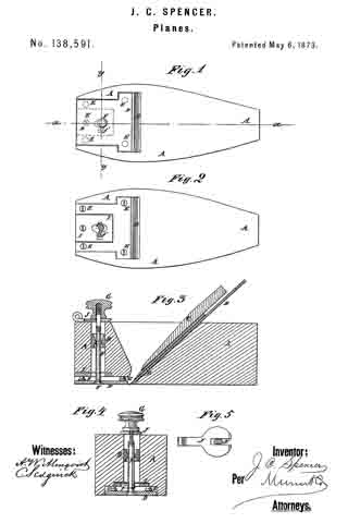
Figure 1 is a bottom or face view of my improved plane. Fig. 2 is the same view as Fig. 1 with the adjustable plate removed. Fig. 3 is a detail longitudinal section of the same taken through the line x x, Fig. 1. Fig. 4 is a detail cross-section of the same taken through the line y y, Fig. 1. Fig. 5 is a detail top view of the adjusting-lever.
Similar letters of reference indicate corresponding parts.
My invention has for its object to furnish an improved plane which shall be so constructed that it may be conveniently, quickly, and accurately adjusted to cnt a thicker or thinner shaving, as may be desired. The invention consists in the improvement of planes, as hereinafter described and pointed out in the claims.
A represents an ordinary plane-stock. B are the plane-irons, and C is the wedge by which the said irons are secured in the said stock. D is a plate, which is placed in a recess in the face of the plane-stock A in front of the edge of the plane-irons B, and which is so arranged as to move longitudinally with the plane-stock, but not laterally. The recess in which the plate D is placed is made deeper than the thickness of the said plate, which plate rests upon the heads of four or more screws, E, screwed into the said stock A in the bottom of the said recess, as shown in Figs. 2, 3, and 4, and in dotted lines in Fig. 1.
By this construction when it becomes necessary to dress off the face of the plane-stock A the screws E are turned in a little so that the recess does not have to be deepened every time the face of the plane-stock is dressed off. The plate D is secured in place by a bolt, F, the head of which is countersunk into the plate D, and which passes up through the plane-stock A and has a hand-nut, G, screwed upon its upper end. The hole through the plane-stock A is made larger than the bolt F, and in it is placed a collar, H, through which the bolt F passes, and which is countersunk from each side to adapt it to serve as a fulcrum to the bolt F to enable said bolt to be used as a lever for adjusting the plate D when the nut G has been loosened. I is a plate let into the stock A in the bottom of the recess in said stock, and in which is formed a hole for the passage of the bolt F. In the plate I at one side of the hole through said plate is formed a notch to receive a toe, f’, formed upon the side of the bolt F to serve as a fulcrum, so that the plate D may be moved to adjust it by turning the bolt F. The upper part of the bolt F is flattened to receive the forked end of the lever J, which is placed between the stock A and the-nut G.
By this construction, by loosening the nut G and operating the lever J the plate D may be adjusted as required.
Having thus described my invention, I claim as new and desire to secure by Letters Patent —
1. The combination of the bolt F, hand-nut G, and fulcrum-collar H with the plane-stock A, and adjustable plate D, substantially as herein shown and described.
2. The combination of the perforated and notched stationary plate I, toe f’, and forked lever J with the plane-stock A, adjustable plate D, bolt F, and nut G, substantially as herein shown and described.
J. CEVILLE SPENCER.
Witnesses:
LYSANDER REDFIELD,
FRANCIS GERVIS.