No. 682,958 – Plane (Thomas M. Seeds, Jr., And Martin Frings) (1901)

[paiddownloads id=”557″]682958


UNITED STATES PATENT OFFICE.

_________________

THOMAS M. SEEDS, JR., AND MARTIN FRINGS,
OF PHILADELPHIA, PENNSYLVANIA.

PLANE.

_________________

SPECIFICATION forming part of Letters Patent No. 682,958, dated September 17, 1901.
Application filed April 12, 1901. Serial No. 55,511. (No model.)

_________________

To all whom it may concern:

Be it known that we, THOMAS M. SEEDS, Jr., and MARTIN FRINGS, citizens of the United States, and residents of Philadelphia, in the county of Philadelphia and State of Pennsylvania, have invented a new and Improved Plane, of which the following is a full, clear, and exact description.

This invention relates to a plane adapted particularly for smoothing floors, but applicable for use in connection with all plane surfaces.

The invention comprises certain peculiar features of construction by which the plane is carried on a wheeled frame and pushed over the floor through the medium of a long handle, thus enabling the operator to stand upright at his work.

This specification is a specific description of one form of the invention, while the claims are definitions of the actual scope thereof.

Reference is to be had to the accompanying drawings, forming a part of this specification, in which similar characters of reference indicate corresponding parts in all the views.

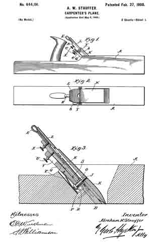
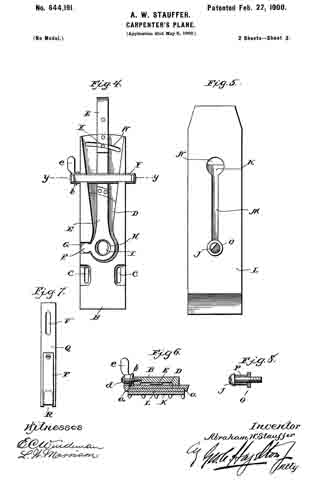
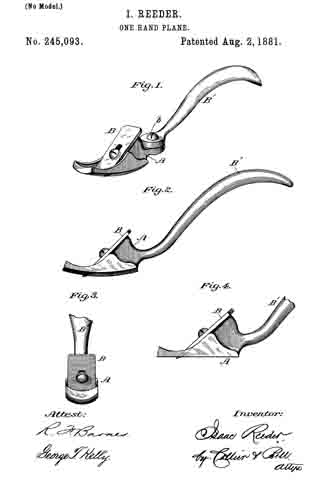
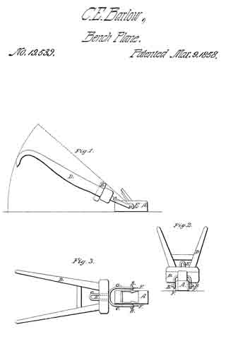
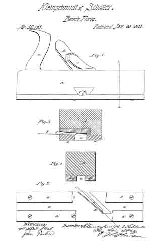
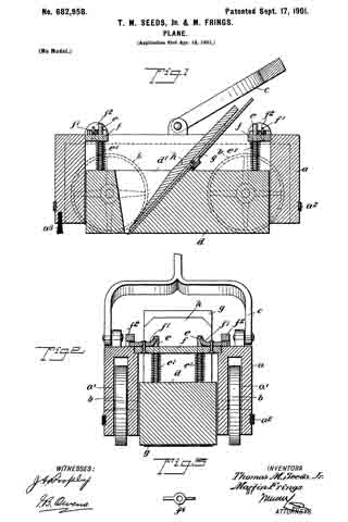
Figure 1 is a longitudinal section of the invention. Fig. 2 is a cross-section thereof; and Fig. 3 is a detail view of one of the dogs, which will be hereinafter described.

a indicates the frame or carriage of the device. This frame is formed with cavities a’
therein, in which are located wheels b, these wheels supporting the frame, andthe cavities a’ being closed at the top to prevent shavings from entering the cavities and clogging the wheels. The frame a has an elastic bead or buffer a2 run around it to prevent marring the woodwork of the building, and at the front portion of the frame is arranged a brush a3, which is adapted to sweep away the dust and other gritty substances prior to the engagement of the blade with the wood.

c indicates the handle, which has a fork at its lower end pivotally connected with the frame a, the handle extending upward within convenient reach of the user, so that the plane may be pushed along much after the manner of the well-known hand lawn-mower.

d indicates a block which is set loosely within the frame a. This block is provided with pins e, which are fastened rigidly thereto and which are projected upward through cross-bars f The cross- bars fare secured rigidly to the frame a by latches f’, which are removably engaged in keepers f2, secured to the frame. Springs e’ bear between the cross-bars f and the block cl and serve to push the block downward. This block cl carries a blade g, which blade is held in the block by a wedge lt. The block d is suitably orificed, as indicated at d’, to receive the blade g and wedge h, so that as the device is moved along the floor the blade in engaging therewith will cut the shavings and throw them into and through the orifice in the block.

The apparatus is adapted to be pushed along on its wheels in the direction desired, and its operation in other respects is very much the same as the usual hand-plane. The block d bears on the ground, and the springs e’ serve to hold the block down, with the blade g properly engaged with the floor. The brush a3 prevents gritty substances from encountering the blade. By manipulating the latches f’ the cross-bars f may be removed from the frame and the block d, with its attached parts, taken out.

Having thus described our invention, we claim as new and desire to secure by Letters Patent —

1. A planer, comprising a wheeled frame, a block movably mounted thereon, means pressing the block downward and a planing-blade held by the block.

2. A planer, comprising a wheeled frame, a block set loosely therein, a spring pressing the block downward, and a planing -blade held by the block.

3. A plane, comprising a wheeled frame, a block mounted loosely therein, a planing-blade held by the block, a cross-bar engaged with the frame, a latch for removably holding the cross-bar in place, and a spring bearing between the cross-bar and block to press the block downward.

In testimony whereof we have signed our names to this specification in the presence of two subscribing witnesses.

THOMAS M. SEEDS, JR.
MARTIN FRINGS.

Witnesses:
NORMAN H. STEVENS,
W. L. STEVENS.

No. 644,191 – Carpenter’s Plane (Abraham W. Stauffer) (1900)

[paiddownloads id=”544″]644191


UNITED STATES PATENT OFFICE.

_________________

ABRAHAM W. STAUFFER, OF PHILADELPHIA, PENNSYLVANIA.

CARPENTER’S PLANE.

_________________

SPECIFICATION forming part of Letters Patent No. 644,191, dated February 27, 1900.
Application filed May 6, 1899. Serial No. 715,818. (No model.)

_________________

To all whom it may concern:

Be it known that I, ABRAHAM W. STAUFFER, a citizen of the United States, residing at Philadelphia, in the county of Philadelphia and State of Pennsylvania, have invented a certain new and useful Improvement in Carpenters’ Planes, of which the following is a specification.

My invention relates to a new and useful improvement in carpenters’ planes, and has for its object to provide a simple and effective means for adjusting the blade of the plane either up and down or sidewise and for clamping and holding the blade firmly in position.

With these ends in view this invention consists in the details of construction and combination of elements hereinafter set forth and then specifically designated by the claims.

In order that those skilled in the art to which this invention appertains may understand how to make and use the same, the construction and operation will now be described in detail, referring to the accompanying drawings, forming a part of this specification, in which —

Figure 1 is a side view of the plane having my improvements embodied therein; Fig. 2, a plan view thereof; Fig. 3, an enlarged section of a portion of the stock of the plane, showing my improvements in section and in position; Fig. 4, a detail view of the bed-block removed from the stock and showing the device for adjusting the bit; Fig. 5, a similar view of the back of the bit; Fig. 6, a section at the line y y of Fig. 4; Fig. 7, a detail view of the clamping-bar, and Fig. 8 represents the clamping-screw.

In carrying out my invention as here embodied, A represents the plane-stock, having fitted therein the bed-block B, which is adjustably secured within the throat of the plane by means of suitable screws passing through the slots C and into the stock. The upper surface of the bed-block is recessed, as shown at D, so as to receive the adjusting-lever E, which has a fulcrum extension F, upon which this lever rocks when being manipulated, said extension fitting within the recess G, formed for that purpose. The adjusting-lever has a hole H formed therein, which registers with the elongated hole I, formed in the bed-block, and through these two holes passes the clamping-screw J, the latter being threaded into the clamp-plate K. This plate is adapted to fit upon the upper surface of the bit L when the latter is in position upon the bed-block, forming a cap therefor, and the clamping-screw J passes through the slot M, formed in the bit, the upper end of which slot is enlarged, as at N , in order that the head of the screw may be withdrawn from the bit. A washer O is placed around the screw and bears against the under side of the bit, and a bushing P is interposed between this washer and the head of the screw in order that when the said screw is run into the clamp-plate the washer will be firmly bound against the under side of the bit, while the clamp-plate will be as firmly bound against the upper surface of the bit, thus tightly securing these parts together. When not assembled, the washer lies within the hole H in the adjusting-lever, permitting the latter to swing thereon.

Q is the clamping-bar, slotted at its lower end, as indicated at R, so as to embrace the screw and bushing thereon and be adapted to draw downward upon the head of said screw. This bar has a ridge S thereon, which acts as a fulcrum, bearing against the under side of the bed-block, so that when the outer end of the bar is forced upward, as hereinafter set forth, the lower end will be swung downward, as will be readily understood, thereby drawing with it the clamping-screw, and consequently the clamp-plate and bit. This action will force the bit firmly against the bed-block, thus holding it against any movement while the plane is in use. A plate-spring T is secured to the under side of the clamping-bar, so as to hold the latter in position and yet permit its movements when being operated to bring about the above-named results.

In order that the outer end of the clamping-bar may be drawn upward with sufficient force to accomplish the results aimed at, a thumb-screw U is passed through the slot V, formed in the bar and threaded in the bed-block, as clearly shown in Fig. 3, and, as is obvious, when this screw is run upon the bed-block it will draw the outer end of the bar upward, the purpose of the slot being to permit the withdrawal of the clamping-bar from the stock when it is desired to release the clamping-screw, and thereby permit the removal of the bit and parts carried thereby.

The upper portion of the bed-block is slotted, as shown at W, and through this slot passes a thumb-screw X, its inner end being threaded into the adjusting-lever E, so that when said lever has been swung to the position which properly adjusts the bit it may be there held by properly manipulating this thumb-screw.

While the bit under ordinary conditions will be held in its adjustment by the clamp-plate, the use of the screw X to hold the adjusting-lever will permit said lever also to act as a means for holding the bit in its adjustment, since so long as the adjusting-lever is held against movement the bit cannot have any lengthwise movement on account of the washer O fitting snugly within the hole H.

The means which I provide for the sidewise adjustment of the bit, which enables the cutting edge of the latter to be properly trued up, is as follows: A cross-slide Y is fitted in dovetailed grooves formed in the bed-block and has lips a formed upon its ends, which embrace the bit, and the movements of this slide are controlled by the spiral cam b, which projects into the groove formed in the slide, said cam being pivoted to the bed-block by the screw d. A thumb-lever e is formed with the cam for its manipulation, so that by drawing this lever to one side or the other the slide will be moved crosswise of the bed-block, and thereby swing the bit upon the washer O as the fulcrum, which, as is obvious, will adjust the cutting edge of the bit, and thereby permit the truing up of the same.

From this description it will be seen that effective means are provided for the adjusting of the bit vertically and also for the truing up of the same, as well as providing for firmly clamping the bit in any adjustment, the latter being especially true since the entire under surface of the clamp-plate fits against the bit, while the under surface of the bit fits against the bed-block, so that when the clamp-plate is drawn downward it will firmly hold said bit.

Having thus fully described my invention, what I claim as new and useful is —

1. In combination with a plane of the character described, a bed-block adjustably secured within the stock, an adjusting-lever fitted within a recess formed in the bed-block, an extension formed with the adjusting-lever and fitted within the recess in the stock, said lever having a hole therethrough, a bit having a central slot therein, a clamp-plate adapted to fit upon the upper surface of the bit, a clamping-screw threaded into the plate, a washer surrounding the screw and adapted to bear against the under side of the bit and fit within a hole formed in the adjusting-lever, a bushing also surrounding the screw and bearing against the washer, a clamping-bar fulcrumed against the under side of the bed-block having its lower end slotted to engage the head of the screw, and means — such as a thumb-screw for drawing the upper end of the clamping-bar toward the bed-block whereby the lower end thereof will be caused to draw the screw and the parts carried thereby downward, as and for the purpose set forth.

2. In combination with a plane of the character described, a bed-block adjustably secured within the stock, an adjusting-lever, an extension formed with the adjusting-lever, a bit adjusted thereby, a clamp-plate, a clamping-screw, a washer and bushing surrounding said screw, a clamping-bar and means for operating the same.

In testimony whereof I have hereunto affixed my signature in the presence of two subscribing witnesses.

ABRAHAM W. STAUFFER.

Witnesses:
MARY E. HAMER,
S. S. WILLIAMSON.

No. 322,304 – Spokeshave And Chamfer-Cutter (James Mander) (1885)

[paiddownloads id=”396″]322304


UNITED STATES PATENT OFFICE.

_________________

JAMES MANDER, OF PHILADELPHIA, PENNSYLVANIA, ASSIGNOR OF
ONE-HALF TO MAURICE R. DILLIN, OF SAME PLACE.

SPOKESHAVE AND CHAMFER-CUTTER.

_________________

SPECIFICATION forming part of Letters Patent No. 322,304, dated July 14, 1885.
Application filed January 24, 1885. (No model.)

_________________

To all whom it may concern:

Be it known that I, JAMES MANDER, a subject of the Queen of Great Britain, residing in the city and county of Philadelphia, State of Pennsylvania, have invented a new and useful Improvement in Chamfer-Cutters and Spoke-shaves, which improvement is fully set forth in the following specification and accompanying drawings, in which —

Figure 1 represents a top or plan view of a chamfer-cutter and spokeshave embodying my invention. Fig. 2 represents a side elevation thereof. Fig. 3 represents a longitudinal section thereof. Fig. 4. represents a transverse section thereof.

Similar letters of reference indicate corresponding parts in the several figures.

My invention consists of a tool which is adapted to be used either as a chamfer-cutter or a spokeshave, as will be hereinafter fully set forth.

Referring to the drawings, A represents a spokeshave, consisting of the stock B, handles C, and bit or blade D, the latter being fitted in diagonally-extending grooves a, formed in the inner sides of the stock.

The back of the stock is cut away, as at b, so that the rear face of the bit is supported by the top cross-bar, c, and side lugs, d, whereby the main portion of the back of the bit below said cross-bar, excepting the small portion contiguous to the lugs d, is uncovered or unobstructed, by which provision the bit is adapted for deep cuts and to perform a greater range of work, limited by the top cross-bar, c, instead of the bottom edge of the back of the stock, as in spokeshaves heretofore constructed.

E represents a frame or case, which, open at top and bottom, is adapted to receive the stock of the spokeshave and the contiguous portions of the handles thereof.

Screws F are swiveled to the spokeshave and tapped in the sides of the case E, whereby provision is made for raising and lowering the spokeshave in said box and thus adjust the bit D therein.

In the bottom edges of the front and rear walls of the case E are recesses G of inverted-V shape, the same constituting guides when the tool is used as a chamfer-cutter, it being noticed that the bit of the spokeshave is the bit of such cutter, and the handles C are employed for operating said cutter.

The tool is presented to the wood so that the latter is coincident with the guide-recesses G, and the tool operated, whereby the wood is readily cut with a chamfer, it being noticed that the depth of the chamfer may be varied or adjusted by properly rotating the screws F, and it will also be noticed that as much of the back of the bit is uncovered as has been set forth, the work of chamfering may be accomplished with facility, the back of the stock presenting no obstructions to the cutting action of the bit to the extreme depth of the guide-recesses G.

Another advantage in leaving the back of the bit uncovered in the manner stated is, that the bit is adapted for cutting what are known as “stop-chamfers,” which may be of various depths, and cannot be produced where the bit is covered in spokeshaves heretofore in use.

I am aware that a spokeshave having a blade adjustable in a recessed stock is old, and also that a combined spoke and chamfer cutter is formed with a casing having recesses thereon, and such I do not broadly claim.

Having thus described my invention, what I claim as new, and desire to secure by Letters Patent, is —

1. In a combined chamfer-cutter and spoke-shave, the spokeshave having a recessed stock, in combination with a blade seated in said stock and supported by a cross-bar of the shave, and a case having recesses in both the front and rear walls of an inverted-V shape, substantially as and for the purpose set forth.

2. The stock B, having a cross-bar, c, and side lugs, d, connected therewith, in combination with a blade secured to said cross-bar c, and supported by said lugs, substantially as and for the purpose set forth.

3. In a combined chamfer-cutter and spokeshave, the stock B of the latter, in combination with the blade D, secured to a cross-bar, c, of said stock, and a case, E, having recesses of inverted-V shape in both the front and rear walls thereof, and screws connected with the spokeshave and engaging with said case, substantially as and for the purpose set forth.

JAMES MANDER.

Witnesses:
JOHN A. WIEDERSHEIM,
A. P. GRANT.

No. 314,338 – Chamfer-Plane (James Mander) (1885)

[paiddownloads id=”388″]314338


UNITED STATES PATENT OFFICE.

_________________

JAMES MANDER, OF PHILADELPHIA, PENNSYLVANIA,
ASSIGNOR OF ONE-THIRD TO MAURICE R. DILLIN, OF SAME PLACE.

CHAMFER-PLANE.

_________________

SPECIFICATION forming part of Letters Patent No. 314,338, dated March 24, 1885.
Application filed December 18, 1884. (No model.)

_________________

To all whom it may concern:

Be it known that I, JAMES MANDER, a subject of the Queen of Great Britain, residing at Philadelphia, in the county of Philadelphia and State of Pennsylvania, have invented certain new and useful Improvements in Chamfer-Planes, of which the following is a specification.

My invention relates to an improvement in planes to be used to chamfer the right-angled edge of a board or strip and form the beveled ends of the chamfer in the manner heretofore accomplished by hand with the chisel, drawing-knife, and level-faced bench-plane.

The invention consists of a bench-plane whose face or working-surface is rabbeted from nearly the edges of its sides to a point within and central with the body of the plane, the lines of the rabbet intersecting each other at an angle of ninety degrees, so that when the chamfered edge of the board is brought to the required depth, as may be regulated by the adjustable face, the sides of said rabbet rest equally and firmly upon the edge and face of the board. The main element of the invention, however, consists of an adjustable sliding face in connection with the rabbeted face of the plane, which is situated in front of the cutting-bit and its retaining-wedge. Said face is also wedged-shaped, and extends down from above the upper surface through the body of the plane and projects within the rabbeted surface any distance desired, and held firmly in position by set-screws that are adjustable in the opposing sides of the plane.

In the accompanying drawings, which make a part of this specification, Figure 1 is a side elevation of my improved plane. Fig. 2 is a longitudinal section of the same. Fig. 3 is an end view. Fig. 4 is a view of the working-face of the plane. Figs. 5 and 6 are side and face views of the adjustable sliding wedge-face D. Fig. 7 is an isometrical view of a portion of a strip chamfered on one corner.

Like letters of reference in all the figures indicate the same parts.

A is the plane-stock; B, the cutting-bit; C, the wedge which retains said bit in position. D is the adjustable sliding face, situated in front of the wedge C and extending from the upper surface down through the body of the plane. It is capable of being adjusted in its altitudinal position by means of the set-screws E E, the ends of which pass into it, the stems of said screws sliding in the slots b b in the sides of the stock.

The mode of operation is as follows: The bit B and its retaining-wedge C are placed in the stock A in the usual manner, the face D having been previously adjusted, with its lower end extending down into the angled rabbeted sides of the stock the required distance below which it is desired to cut the chamfer. The plane is then manipulated in the customary manner, with one side of the angled face upon the edge and the other upon the surface of the board, nearly the required length of the charnfer, cutting the end bevel, c, during its progress, when it is reversed and worked (left-handed) to cut the other end bevel, c’, and the remaining portion of the chamfer down to its level. The working-surface of the adjustable face D extends back only to the front of the cutting-edge of the bit B, with sufficient room between it and the bit for the upward passage of the shaving to the throat of the plane. The face of the stock being rabbeted its entire length presents no obstacle to the bit acting as a chisel or similar tool, thereby cutting the beveled end of the chamfer.

In lieu of a flat chamfer, the corner of the board may be beaded, reeded, fluted, or given any desired configuration by a corresponding change in the face of the adjustable stop and in the cutting-edge of the bit.

Having thus described the construction and operation of my improved plane, what I claim therein as new, and desire to secure by Letters Patent, is —

1. The adjustable face D, in combination with the rabbeted faced stock A, said face D being cofined within the body of the stock A by means of the set-screws E E, which pass through the sides of the stock to engage the face D, whereby said face D may be raised or lowered to suit the depth of chamfer required, substantially as described.

2. The stock A, which forms the stop or depth of chamfer, rabbeted throughout its length from a central point at an angle of ninety degrees each way to its sides, in combination with the adjustable face D, which is secured in the stock and made adjustable therein by means of the screws E E and cutting-bit B, thus leaving the back of the bit free to act as a chisel for cutting the beveled end of the chamfer.

JAMES MANDER.

Witnesses:
THOMAS J. BEWLEY,
FRANK CRAVEN.

No. 277,767 – Bench-Plane (Frank A. Mershon) (1883)

[paiddownloads id=”335″]277767


UNITED STATES PATENT OFFICE.

_________________

FRANK A. MERSHON, OF PHILADELPHIA, PENNSYLVANIA.

BENCH-PLANE.

_________________

SPECIFICATION forming part of Letters Patent No. 277,767, dated May 15, 1883.
Application filed March 1, 1883. (No model.)

_________________

To all whom it may concern:

Be it known that I, FRANK A. MERSHON, a citizen ofthe United States, and a resident of Philadelphia, Pennsylvania, have invented certain Improvements in Molding-Planes, of which the following is a specification.

My invention relates to that class of molding-planes in which a wooden stock is combined with a detachable sole-plate; and the object of my invention is to afford means for readily attaching the sole-plate to and detaching it from the stock, and for steadily retaining the former on the latter, as fully described hereinafter.

In the accompanying drawings, Figure 1 is a perspective view of my improved molding-plane, showing the sole-plate detached; Fig. 2, a transverse section, and Fig. 3 a longitudinal section of part of the plane.

The stock A of the plane is of wood and the sole-plate B of metal, the under side of this plate having such longitudinal ribs and grooves as the pattern of the molding to be planed may require. The sole-plate has at each end a transverse flange, a, and a longitudinal flange, b, fitted snugly in a recess in the stock, as shown in Fig. 2. There is at each end of the stock a spring-catch, D, for retaining the sole-plate, each catch consisting in the present instance of a spring, e, secured to the stock, and having a pin, d, for entering a hole in the transverse flange a. The stock, it should be understood, is cut away at each end to receive the said flange, and is further cut away to permit the free play of the spring, the flange being so rounded at the upper edge on the inner side that when the stock is applied to the sole-plate by depressing the former onto the latter the springs will yield without being manipulated, and will recoil when the stock reaches the plate, the pins entering the holes in the flanges, and thus holding the two parts of the plane together.

While the spring-retainers will suffice to hold the plate in place, I prefer, as an additional security, to use two set-screws, E, each provided with a head, f, constructed for the convenient turning of the screw by the finger and thumb, the stem of the screw passing through the stock, and its threaded end being adapted to a threaded projection, m, on the sole-plate. This projection is made tapering, and is adapted to an orifice of corresponding form in the under side of the stock. Even if no set-screws are used, I prefer to make these projections on the plate, as they facilitate the adjustment of the stock to its proper position on the plate, and serve as steady-pins for determining the proper lateral and longitudinal relation of the plate to the stock.

It will be seen that whenever a change in the pattern of the molding is required the plate can be readily detached to make way for another, the under side of which conforms with the desired molding, a change of plane irons or bits F being also required. The pins d are preferably tapered, so that they tend to draw the sole-plate firmly to its seat on the stock.

I claim as my invention —

1. A molding-plane in which a stock, A, provided at the ends with spring-catches, is combined with a sole-plate, B, having flanges a, constructed to be retained by the said catches of the stock, substantially as set forth.

2. The combination of the stock A, and a detachable sole-plate having tapering projections adapted to it closely correspondingly-tapered orifices in the stock, and devices, substantially as described, for securing the plate to the stock, substantially as set forth.

3. The combination of the stock A and its spring-catches with the flanged sole-plate and its tapering projections m, adapted to orifices in the stock, substantially as specified.

4. The combination ot the stock A, its spring-catches, the flanged sole-plate, and its tapering projections m, with the set-screws E.

In testimony whereof I have signed my name to this specification in the presence of two subscribing witnesses.

FRANK A. MERSHON.

Witnesses:
HARRY L. ASHENFELTER,
HARRY SMITH.

No. 258,971 – Reed-Plane (Frederick V. Yeager) (1882)

[paiddownloads id=”321″]258971


UNITED STATES PATENT OFFICE.

_________________

FREDERICK V. YEAGER, OF PHILADELPHIA, PENNSYLVANIA.

REED-PLANE.

_________________

SPECIFICATION forming part of Letters Patent No. 258,971, dated June 6, 1882.
Application filed August 26, 1881. (No model.)

_________________

To all whom it may concern:

Be it known that I, FREDERICK V. YEAGER, a citizen of the United States, and a resident of the city and county of Philadelphia, in the State of Pennsylvania, have invented certain new and useful Improvements in Reed-Planes, of which the following is a specification, reference being had to the accompanying drawings, wherein —

Figure 1 is a side elevation of my improved reed-plane. Fig. 2 is an elevation of the reverse side of the same. Figs. 3 and 4 are tranverse vertical sections, and Fig. 5 is an inverted plan of the same.

My invention has for its object to provide a plane for working reeds across the grain of wood. Heretofore such result has been obtained by means of a saw and chisel, and to produce a cluster of reeds by such means required great care and consumed much time and labor, thereby making the operation one of extreme tediousness and expense. With my improved plane, however, reeds can be worked across the grain of wood with ease and rapidity.

My invention consists in the novel construction and arrangement of the plane, as hereinafter more fully described.

Referring to the accompanying drawings, A represents the stock of the plane, B the hit thereof, and C the wedge for securing said bit in an opening in said stock. The bit B is formed with a projecting convex cutter, b, being outside ground, as shown at b’.

D D’ are cutters, passing through an opening, a, in the forward part of the plane, and are held therein by means of a wedge, E. Said cutters are placed a distance apart equal to the width of the reeds designed to be worked, and have their lower or cutting edges serrated, as shown at d.

F represents the sole of the plane, made in three sections, f f 1 f2. The sections f f2 are stationary. The section f1 is formed with a slot, f4, through which passes a screw, f5, into the stock A, as plainly shown in Fig. 4. By loosening said screw the section f1 may be adjusted to and from the cutting-edge of the bit B to regulate the thickness of the chip or shaving designed to be cut, so as to insure smoothness of working.

G is a gage, secured to stock A by pivoted links g g; and H is a thumb-screw passing through a curved or other suitable slot, g’, in the gage, and screws into the stock A, the effect whereof is that when said gage is raised or lowered, and the thumb-screw H turned, its head h will impinge against said gage, and will thereby retain the latter in its adjusted positions.

The operation is obvious, and as follows: In forming the first reed of a cluster the gage G is raised, as shown in Figs. 2 and 3, and the plane is moved to and fro across the grain of the wood. During each such forward movement the cutters D D’ scribe or cut two parallel lines in advance of the bit B, so that the cutting-edge of the latter merely removes the chip or shaving between the lines so formed by the cutters D D’. Consequently a smooth or unbroken reed can be formed across the grain of wood by such plane. After the first reed is worked the gage G is lowered by flrst loosening the thumb-screw H, which allows the gage to fall, whereupon it is held in such position by turning said screw until its head binds against the gage. The latter is then placed in the outside crevice of said first-formed reed, so that the latter forms a guide to assist in the working of the second reed. By such means each succeeding reed is formed parallel to its immediate predecessor, such operation being plainly illustrated in Fig. 4.

What I claim as my invention is —

1. In a plane for working reeds across the grain of wood, the combination of advance cutters D D’, having serrated cutting-edges d, plane-bit B, having convex cutter b, outside ground or bevel, b’, sole F, having adjustable section f1, and gage G, secured to the body of the plane by links g g, and provided with a thumb-screw, H, substantially as shown and described.

2. In a plane for working reeds across the grain of wood, the combination of main bit B, having convex cutter b, outside ground or bevel, b’, advance cutters D D’, provided with serrated cutting-edges d d, and adjustable sole-section f1, substantially as shown and described.

In testimony that I claim the foregoing I have hereunto set my hand this 23d day of August, 1881.

FREDK. V. YEAGER.

Witnesses:
CHAS. W. HOPPLE,
GEORGE H. VANDEGRIFT.

No. 245,093 – One-Hand Plane (Isaac Reeder) (1881)

[paiddownloads id=”315″]245093


UNITED STATES PATENT OFFICE.

_________________

ISAAC REEDER, OF PHILADELPHIA, PENNSYLVANIA, ASSIGNOR OF ONE-HALF TO ROBERT S. DUFF, OF SAME PLACE.

ONE-HAND PLANE.

_________________

SPECIFICATION forming part of Letters Patent No. 245,093, dated August 2, 1881.
Application filed May 26, 1881. (No model.)

_________________

To all whom it may concern:

Be it known that I, ISAAC REEDER, a citizen of the United States,residing at Philadelphia, in the county of Philadelphia and State of Pennsylvania, have invented certain new and useful Improvements in Wood-Workers’ Finishing-Tools; and I do hereby declare the following to be a full, clear, and exact description of the invention, such as will enable others skilled in the art to which it appertains to make and use the same, reference being had to the accompanying drawings, and to the letters or figures of reference marked thereon, which form a part of this specification.

This invention is designed for finishing or smoothing moldings, &c., and may be variously shaped to suit the different conformations of the surfaces upon which it is used.

In the drawings, Figure 1 is a perspective view of one form of the invention. Fig. 2 is a side view of a niodided form of the invention. Fig. 3 is a front view of Fig. 2. Fig. 4 is a side view of a portion of the tool, showing a further modification.

Similar letters of reference indicate similar parts in the respective figures.

Referring more particularly to Fig. 1, A is a metal stock, the lower or operating face of which is, as viewed endwise or in transverse section, made convex or of other formation to suit the character of the work. The bed of the stock, or the surface upon which the plane-bit rests, is placed at the usual angle. The lower face of the stock is curved longitudinally, in order that the bit may be given the desired bite into the wood without shifting its position relatively to the stock.

B represents the bit, which is of a construction similar to that heretofore employed in planes, the bit being slotted and secured to the bed of the stock by a set-screw in a common manner. The cutting-edge of the bit is ground to the ordinary acute angle, and is made to conform to the transverse shape of the operating-face of the stock. The bit, as here shown, is not used. with a cover, but one may be used if desired, in which case the lower edge of the cover should be so formed as to be concentric with the cutting-edge of the bit, and fixed at a short distance above it to coincide with the steel face in the ordinary manner.

The front portion or lip of the stock is hollowed out at its upper surface, and the cavity thus formed may serve to collect the minute shavings which in the operation of the tool are passed through the aperture cut in the stock for the insertion of the bit; or it may serve as a rest for the finger or thumb of the operator, who can thus place a pressure on the lip of the stock and increase the bite of the bit.

At the rear of the stock is formed an ear or lug, to which the handle B is secured by a set-screw, b. This handle is adapted to be moved upon the screw as a pivot obliquely to the line of movement of the tool, and held in the required position.

In Fig. 2 the handle is shown solid with the stock, but in other respects the tool agrees with the description above given.

In Fig. 4 the lower or operating face of the stock is flat, the edge of the bit a, being necessarily of corresponding shape.

The tool is specially designed for finishing wood moldings, and when so employed may take the place of the round-nosed chisel and sand-paper at present commonly used. The tool may, however, be used with advantage in finishing other surfaces of soft material.

I claim as my invention —

As an improvement in tools for finishing or smoothing moldings, &c., a metallic stock whose front portion or lip is constructed to serve as a finger or thumb rest, combined with an adjustable bit, and a pivoted handle capable of horizontal adjustment obliquely to the line of movement of the tool, substantially as set forth.

In testimony whereof I affix my signature in presence of two witnesses.

ISAAC REEDER.

Witnesses:
J. SNOWDEN BELL,
GEORGE T. KELLY.

No. 181,649 – Improvement In Plane-Irons (Henry Disston) (1876)

[paiddownloads id=”267″]181649


UNITED STATES PATENT OFFICE.

_________________

HENRY DISSTON, OF PHILADELPHIA, PENNSYLVANIA.

IMPROVEMENT IN PLANE-IRONS.

_________________

Specification forming part of Letters Patent No. 181,649, dated August 29, 1876; application filed April 29, 1876.

_________________

To all whom it may concern:

Be it known that I, HENRY DISSTON, of Philadelphia, Pennsylvania, have invented certain Improvements in Plane-Irons, of which the following is a specification:

The object of my invention is to so construct a plane-bit that it may be more readily and truly ground and sharpened than ordinary edge-tools of this class, a further object of my invention being economy in the consumption of material in making the tools.

In the accompanying drawing, Figure 1 represents a front view of a plane-bit made according to my invention; Fig. 2, a section on the line 1 2; Fig. 3, a transverse section on the line 3 4; Fig. 4, a modification of Fig. 3.

The plane-bit A (shown in Figs. 1, 2, and 3) has a series of parallel grooves or indentations, a, on that side from which the tool is beveled to a sharp edge, the grooves being of such a depth that they will extend into the beveled portion d, as shown. With the exception of these grooves or indentations the plane bit is similar to those of ordinary construction; and, as it is no thicker than usual, the ribs between the grooves impart the desired rigidity, While less material is consumed an its manufacture than in making common bits.

The grinding of the beveled edge of a bit thus constructed can be more readily accomplished than that of an ordinary bit, for the reason that there is less metal to remove, and it is much easier to grind truly an indented surface than one without grooves, as will be readily understood by those familiar with grinding operations.

The plane-bit can be readily manufactured by means of two dies, one being flat, for the flat face of the bit, the other having ribs corresponding with the desired indentations, and the two dies being used in connection with any ordinary drop press.

It is not essential that the indentations or grooves and intervening ribs should be of the precise shape shown in the sectional view, Fig. 3. They may, for instance, be of the form shown in Fig. 4, with good results as regards the facility of grinding, sharpening, and economizing of material.

I claim as my invention —

As a new article of manufacture, a plane-bit having grooves or indentations on its beveled side, as specified.

In testimony whereof I have signed my name to this speciiication in the presence of two subscribing witnesses.

HENRY DISSTON.

Witnesses:
A. H. SHOEMAKER,
GEO. S. GAUDY.

No. 161,213 – Improvement In Bench-Planes (Asahel H. Dean) (1875)

[paiddownloads id=”239″]161213


UNITED STATES PATENT OFFICE.

_________________

ASAHEL H. DEAN, OF PHILADELPHIA, PENNSYLVANIA.

IMPROVEMENT IN BENCH-PLANES.

_________________

Specification forming part of Letters Patent No. 161,213, dated March 23, 1875; application filed January 30, 1875.

_________________

To all whom it may concern:

Be it known that I, ASAHEL H. DEAN, of Philadelphia, Pennsylvania, have invented certain Improvements in Bench-Planes, of which the following is a specification:

The main object of my invention is to so construct a plane having a metal body or frame as to admit of the ready withdrawal, replacing, and adjustment of the plane-bit, and this object I attain in the manner which I will now proceed to describe, reference being had to the accompanying drawings, in which —

Figure 1 is a vertical section of my improved plane; Fig. 2, perspective view of the lever-clamp; Fig. 3, a perspective view of the plane; and Fig. 4, views illustrating part of my invention.

The body of the plane consists of the base A and two side pieces or cheeks, B and B’, the whole being, in the present instance, cast in one piece. The handle E of the plane and the knob F are secured to the base A by screws, in the manner shown in Fig. 1. The plane iron or bit C, which is of the usual construction, and has the usual cap plate h’, bears against a projection, j, of the wooden handle and against a shoulder, i, on the base, the cutting-edge of the bit projecting through a slot in the said base in the ordinary manner, and the bit being confined to its place by a lever-clamp, H, best observed in the perspective views, Figs. 2, 3, and 4. This clamp has on one side a segmental projection adapted to a circular opening in the cheek B, and on the opposite side a ring, f, adapted to a segmental groove, h, formed in the outer face of the cheek B. The projection e and ring f constitute the pivots or fulcrums of the lever-clamp, the upper end of which is caused to bear on the cap-plate by a set-screw, d, in a manner too clearly indicated by the drawing to need description, and to confine the bit to the shoulder on the base and the projection j of the handle.

After loosening the set~screw d, and thereby releasing from its bearings the lever-clamp H, the latter can be removed laterally, its projection e from the cheek B and its ring f from the segmental recess of the cheek B’, thereby permitting the plane-bit to be withdrawn, the clamp being as readily introduced into its place and secured after the adjustment of the plane-bit.

The bearing of the bit on the wooden handle E is an important feature of my invention, for the wood presents a surface to which the bit can be more firmly secured without danger of slipping, when the plane is subjected to accidental jars, than a metal surface.

I claim as my invention —

I. A plane in which the bit is confined to its bearings by a lever-clamp, H, constructed for connection to, and lateral withdrawal from, the frame or body of the plane, substantially in the manner described.

2. The clamp H, its set-screw d, projection e, and ring f, in combination with the cheek B, having an opening adapted to the said projection, and the cheek B, having a segmental recess adapted to the said ring, all substantially as set forth.

3. A plane having a metal body or frame, a wooden handle, and a retaining-screw, or its equivalent, between which and the handle the plane-bit is clamped, all substantially as described.

In testimony whereof I have signed my name to this specification in the presence of two subscribing witnesses.

ASAHEL H. DEAN.

Witnesses:
HUBERT HOWSON,
HARRY SMITH.

No. 17,921 – Stock For Smoothing Planes (John F.W. Erdmann) (1857)

[paiddownloads id=”49″]17921


UNITED STATES PATENT OFFICE.

_________________

JOHN F. W. ERDMANN, OF PHILADELPHIA, PENNSYLVANIA.

STOCK FOR SMOOTHING-PLANES.

_________________

Specification of Letters Patent No. 17,921, dated August 4, 1857.

_________________

To all whom it may concern:

Be it known that I, J. F. W. ERDMANN, of Philadelphia, county of Philadelphia, in the State of Pennsylvania, have invented a new and useful Improvement in Smoothing-Planes; and I do hereby declare that the following is a full and exact description thereof, reference being had to the accompanying drawings and to the letters of reference marked thereon.

The nature of my invention consists in certain improvements as hereinafter described in smoothing (or scraping) planes for the use of cabinet makers and others.

To enable others skilled in the art to make and use my invention I will proceed to describe its construction and operation, reference being had to the accompanying drawings, where —

Figure 1 represents a longitudinal section; Fig. 2, a side elevation; Fig. 3, an end elevation; Fig. 4, a top view of plane stock;
Fig. 5, side and edge views of plane iron, and Fig. 6, side and edge views of wedge.

The stock (A) is constructed as that of the ordinary smoothing plane with the exception of the mortise for the bit (B) being made with a reversed inclination to that usually given.

The plane rim or bit (B) is constructed as shown with two working ends or four cutting edges which may be used alternately until all require sharpening.

(C) is the wedge which is constructed so that it may be applied either before or behind the bit (B) which is perfectly plain on its sides.

(D) is an elastic strip inserted in the back of the stock at the throat and against which the bit (B) is pressed when secured by the wedge (O).

It will be observed that by the arrangement of the four edged scraping bit (B) in the ordinary smoothing plane stock, an efficient and economical tool is made, which may be constructed to adapt itself to every variety of work, while by constructing the same as described the cutting angle of the bit may be varied by simply shifting the wedge (C) from one to the other side of the said bit, always pressing the said bit firmly against the elastic strip (D), which latter effectually prevents any shaving from entering the throat of the plane back of the iron, and also makes the plane work more easily, and satisfactorily from the fact of making the iron very slightly elastic.

I am aware that an iron similar to mine is known as a scraper and that irons have been adjusted in stock, with mechanisms for changing the cutting (or scraping) angle and do not wish therefore to be understood as claiming such features as my invention, but

Having described the construction of my improved plane what I claim as my invention and desire to secure by Letters Patent is:-

Placing in the throat of the plane back of the iron, the elastic strip (D) substantially as and for the purposes described.

In testimony whereof I have hereunto set my hand this 28th day of May, 1857.

JOHN FR. W. ERDMANN.

Witnesses:
D. MAJOR GODWIN,
WM. T. GODWIN.

No. 19,539 – Floor Plane (Charles E. Barlow) (1858)

[paiddownloads id=”72″]19539


UNITED STATES PATENT OFFICE.

_________________

CHARLES E. BARLOW, OF PHILADELPHIA, PENNSYLVANIA.

FLOOR-PLANE.

_________________

Specification of Letters Patent No. 19,539, dated March 9, 1858.

_________________

To all whom it may concern:

Be it known that I, CHARLES E. BARLOW, of the city and county of Philadelphia and State of Pennsylvania, have invented a new and useful Improvement in Planes for Planing Decks of Vessels and Boarded Floors; and I do hereby declare that the following is a full and exact description thereof, reference being had to the accompanying drawing, and to the letters of reference marked thereon, making a part of this speciflcation.

The nature of my invention consists in providing an ordinary carpenter’s plane with a frame, so formed and connected as to enable the operator to stand in the most advantageous position while planing the decks of vessels, boarded floors and other similar surfaces.

Figure 1 is a longitudinal elevation, Fig. 2 is an end view and F ig. 3 is a plan of my improved plane.

A represents a carpenter’s plane of the usual shape having a pivot (B) firmly fixed to each side, said pivots (B) working freely in the bearings formed on the lower part of an iron frame (C). The upper part of the iron frame (C) passes through the lower stay of the wood frame (D) and is secured thereto by a key (E). The upper part of wood frame (D) is formed somewhat like the handles of a plow, the length of which may be made to suit the workman. The total length of the whole (for a man of a medium height) is about five feet. The plane (A) may be detached from the iron frame (C) by withdrawing the pins (E).

When planing off certain kinds of timber I find it advantageous to weight the plane, by attaching a plate of lead to the top of the (A) to slide more steadily over the article being planed but relieves the operator from the necessity of pressing the said plane (A) on to the said article being planed.

The workman when using my improved plane can place himself in any desirable position without moving the plane (A) from the article being planed. That is to say in consequence of the frame (C) being attached to the plane (A) by the pivots B as above stated-the operator may elevate or depress the handles of frames (D) and (C) without affecting the position of the plane A which will therefore in all cases accommodate itself to the work.

The plane A and its connections are worked backward and forward substantially in the same manner as an ordinary plane when being used on a carpenter’s bench; and the decks of vessels, boarded fioors and other similar surfaces can be thereby planed more expeditiously, and with far less manual labor than is required by the usual mode of operation, which is not only tedious and laborious, but painful in consequence of the workman being compelled to rest on his knees while performing the same.

I do not claim broadly the manner of connecting the handle with the stock. But

What I do claim, as a new article of manufacture, is —

The construction of a self adjusting floor plane, with its handle or handles hinged to the stock substantially as described, for the purposes set forth.

CHARLES E. BARLOW.

Witnesses:
JAMES ECCLES,
JOHNN CLOUDS.

No. 43,360 – Improvement In Bench Planes (Stephen Williams) (1864)

[paiddownloads id=”105″]43360


UNITED STATES PATENT OFFICE.

_________________

STEPHEN WILLIAMS, OF PHILADELPHIA, PENNSYLVANIA.

IMPROVEMENT IN BENCH-PLANES.

_________________

Specification forming part of Letters Patent No. 43,360, dated June 28, 1864.

_________________

To all whom it may concern:

Be it known that I, STEPHEN WILLIAMS, of Philadelphia, in the county of Philadelphia and State of Pennsylvania, have invented a new and useful Improvement in Smoothing-Planes; and I do hereby declare that the following is a full, clear, and exact description thereof, which will enable others skilled in the art to make and use the same, reference being had to the accompanying drawings, making a part of this specification, in which —

Figure 1 is a side sectional elevation of my invention. Fig. 2 is a. plan view of the same.

Similar letters of reference indicate like parts.

I denominate my improvement the “universal smoothing-plane,” because it belongs to that variety of planes in which the face is made changeable, so that it may be conveniently adapted to the planing of curved as well as straight surfaces.

By the use of my improvement surfaces that are convex, concave, or straight may be easily worked, the thee of the tool being readily changed from one form to another to suit the surface to which it is to be applied.

A is a hollow box, of the exterior form shown, made, in one or more pieces, of iron or other materials, receiving the usual wedge, B, and plane iron C, which passes obliquely through the box A, a nipple, a, at its front end to receive the blow of the hammer during adjustment. The remaining body of the plane is composed of movable sections or blocks D, filted together, some of them, D’, made to conform at their upper ends to the shape of the box A, against which said ends press, as shown. The blocks or sections D D’ and the box A are bound together by an exterior hoop or band, E, of metal, which incloses them. The end piece, b,.of the band E is made sufficiently thick at its middle to have formed in it a screw-nut, through which a binding-screw, F, passes to press against the outer section or block, D, as shown. By turning the screw F the blocks or sections D D’ and box A will all be firmly bound or pressed together, and, as their lower ends constitute the surface of the plane, it is only necessary, in order to change the form of the face of the plane, to vary the position of the sections and box in respect to each other and then bind them by the screw F. Upon each alternate surface of the sections D D’ and box A there is a tongue and groove, c, d, which prevents lateral displacement of the sections, but allows of vertical adjustment. Upon the exterior of box A there are projecting tongues or ledges e e, between which the band E passes. These ledges prevent the displacement of the band E. The lower extremities of the sections D D’ and box A are made slightly rounded, so as to afford greater facility in moving the plane, prevent the edges of the sections from catching on the surface of the work, &c.

The black lines in Fig. 1 show the plane as adjusted to plane a concave surface. The red lines show the position of the parts when adjusted to plane a flat surface, and the blue lines show the adjustment for a convex surface.

I do not confine myself to the precise form of parts herein shown, as that may be varied according to the skill of the maker; but,

Having thus described my invention, I claim as new and desire to secure by Letters Patent —

1. The construction of the body ofthe plane of movable blocks or sections, substantially in the manner and for the purpose herein shown and described.

2. The combination of the movable sections D D’, independent plane bit-holder A, inclosing-band E, and screw F, all arranged and employed as described.

STEPHEN WILLIAMS.

Witnesses:
HENRY MCNEILL,
HENRY BENJAMIN.

No. 52,173 – Tools For Making Lighters (Albert Kleinschmidt And Francis Schlater) (1866)

[paiddownloads id=”112″]13957


UNITED STATES PATENT OFFICE.

_________________

ALBERT KLEINSCHMIDT AND FRANCIS SCHLATER, OF PHILADELPHIA, PENNSYLVANIA.

IMPROVEMENT IN TOOLS FOR MAKING LIGHTERS.

_________________

Specification forming part of Letters Patent No. 52,173, dated January 23, 1866.

_________________

To all whom it may concern:

Be it known that I, ALBERT KLEINSCHMIDT AND FRANCIS SCHLATER, of Philadelphia, Pennsylvania, have invented an Instrument for Making Lighters; and we do hereby declare the following to be a full, clear, and exact description of the same, reference being had to the accompanying drawings, and to the letters of reference marked thereon.

Our invention consists of a plane having a longitudinal groove, a diagonal cutter, and diagonal groove, the whole being arranged, substantially as described hereafter, so as to cut from a strip of wood coiled shavings of a tapering form, applicable to the lighting of cigars, &c.

In order to enable others to make and use our invention, we will now proceed to describe its construction and operation.

On reference to the accompanying drawing, which forms a part of this specification, Figure 1 is a side view of our plane for making lighters; Fig. 2, an inverted plan view, with parts of the plane removed; Fig. 3, a transverse vertical section on the diagonal line 1 2, Fig. 2, and Fig. 4 a transverse section on the line 3 4, Fig. 1.

Similar letters refer to similar parts throughout the several views.

A represents the body of the plane, which is similar, as regards external form, to ordinary planes, and is provided with the usual handle a. A cutter, B, passes through an opening in the body of the plane, and is secured by a wedge, C, the cutter being arranged diagonally and at the near edge of a diagonal groove, j, formed in the under side of the body of the plane. (See Fig. 2.)

It should be understood that the opening in the body of the plane for the reception of the cutter and wedge is entirely filled by the latter.

To the under face of the body of the plane are secured two strips, d and d’, so as to form a longitudinal groove, e, one of these strips covering part of the diagonal groove f, and thereby converting the latter into an opening, h, on one side of the plane, Fig. 1.

In operating with the above-described tool a piece of pine or other wood as free as possible frorn knots is selected, the piece being of the same width as or a trifle narrower than the width of the groove e between the strips d d’. The piece of wood is properly secured edge upward, and the operator, placing his plane so that the edge of wood is situated between the grooves, proceeds to remove shaving after shaving. Each shaving, as it is being cut from the wood, will, owing to the diagonal position of the knife and the groove f pass through the opening h in the form of a tapering coil, as seen at x, Fig. 3. The coiled shavings thus formed retain their uniform shape and neat appearance, and are especially useful for lighting cigars, &c.

We claim as our invention and desire to secure by Letters Patent —

The within-described plane, with its longitudinal groove e, diagonal cutter B, and diagonal groove j, the whole being arranged substantially as and for the purpose herein set forth.
In testimony whereof we have signed our names to this specification in the presence of two subscribing witnesses.

ALBERT KLEINSCHMIDT.
FRANCIS SCHLATER.

Witnesses:
CHARLES E. FOSTER,
JOHN WHITE.