No. 399,287 – Gage Attachment For Planes (George H. Russell) (1889)

[paiddownloads id=”446″]399287


UNITED STATES PATENT OFFICE.

_________________

GEORGE H. RUSSELL, OF PITTSFIELD, MASSACHUSETTS.

GAGE ATTACHMENT FOR PLANES.

_________________

SPECIFICATION forming part of Letters Patent No. 399,287, dated March 12, 1889.
Application filed October 27, 1888. Serial No. 289,264. (No model.)

_________________

To all whom it may concern:

Be it known that I, GEORGE H. RUSSELL, a citizen of the United States, residing at Pittsfield, in the county of Berkshire, State of Massachusetts, have invented certain new and useful Improvements in Gage Attachments for Planes, of which the following is a specification, reference being had therein to the accompanying drawings.

This invention has relation to heading or grooving planes, and especially to an adjusting attachment for the same, whereby said plane is adapted for forming beads or grooves of varying widths; and among the prime objects in view are to provide a simply constructed and applied gage that can be easily and quickly adjusted for different-sized grooves or heads, which grooves or beads shall be uniform.

Other objects and advantages of the invention will hereinafter appear, and the novel features thereof will he particularly pointed out in the claim.

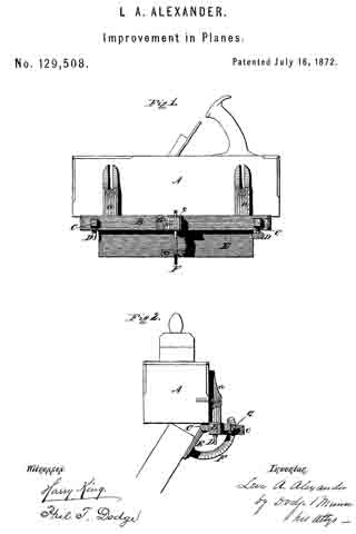
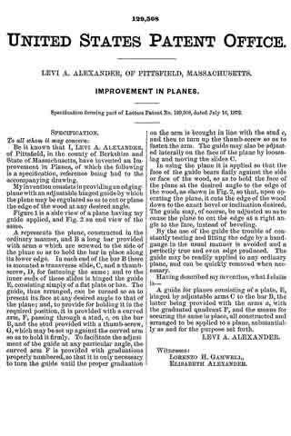
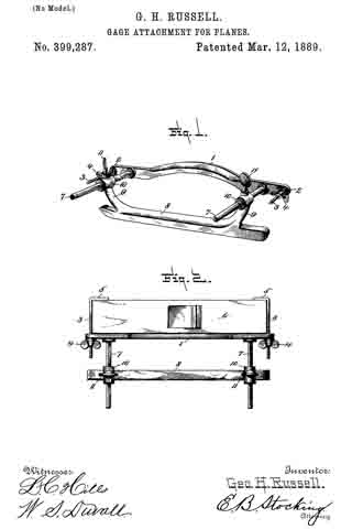
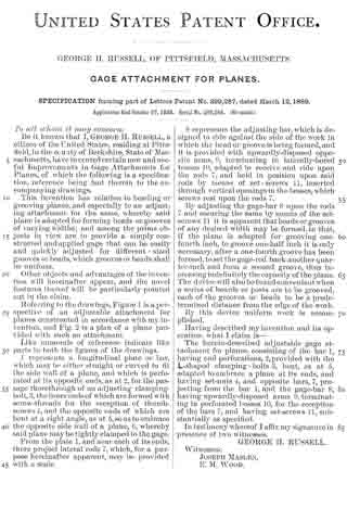
Referring to the drawings, Figure l is a perspective of an adjustable attachment for planes constructed in accordance with my invention, and Fig. 2 is a plan of a plane provided with such an attachment.

Like numerals of reference indicate like parts in both the figures of the drawings.

1 represents a longitudinal plate or bar, which may be either straight or curved to fit the side wall of a plane, and which is perfo-
rated at its opposite ends, as at 2, for the passage theirethrough of an adjusting clamping-bolt, 3, the inner ends of which are formed with screw-threads for the reception of thumb-screws 4, and the opposite ends of which are bent at a right-angle, as at 5, so as to embrace the opposite side wall of a plane, 6, whereby said plane may be tightly clamped to the gage.

From the plate 1, and near each of its ends, there project lateral rods 7, which, for a purpose hereinafter apparent, may he provided with a scale.

8 represents the adjusting-bar, which is designed to ride against the side of the work in which the head or groove is being formed, and it is provided with upwardly-disposed opposite arms, 9, terminating in laterally-bored bosses 10, adapted to receive and ride upon the rods 7, and held in position upon said rods by means of set-screws 11, inserted through vertical openings in the bosses, which screws rest upon the rods 7.

By adjusting the gage-bar S upon the rods 7 and securing the same by means of the set-screws 11 it is apparent that beads or grooves of any desired width may be formed, in that, if the plane is adapted for grooving one-fourth inch, to groove one-half inch it is only necessary, after a one-fourth groove has been formed, to set the gage-rod back another quarter-inch and form a second groove, thus increasing indefinitely the capacity of the plane. The device will also he found convenient when a series of boards or posts are to be grooved, each of the grooves or heads to be a predetermined distance from the edge of the work.

By this device uniform work is accomplished.

Having described my invention and its operation, what I claim is —

The herein-described adjnstable gage attachment for planes, consisting of the bar 1, having end perforations, 2, provided with the L-shaped clamping-bolts 3, bent, as at 5, adapted to embrace a plane at its ends, and set-nuts 4, and opposite bars, 7, projecting from the bar 1, and the gage-bar 8, having upwardly-disposed arms 9, terminating in perforated bosses 10, for the reception of the bars 7, and having set-screw 11, substantially as specified.

In testimony whereof I affix my signature in presence of two witnesses.

GEORGE H. RUSSELL.

Witnesses:
JOSEPH MASLEN,
E. M. WOOD.

No. 129,508 – Improvement In Planes (Levi A. Alexander) (1872)

[paiddownloads id=”200″]129508


UNITED STATES PATENT OFFICE.

_________________

LEVI A. ALEXANDER, OF PITTSFIELD, MASSACHUSETTS.

IMPROVEMENT IN PLANES.

_________________

Specification forming part of Letters Patent No. 129,508, dated July 16, 1872.

_________________

To all whom it may concern:

Be it known that I, LEVI A. ALEXANDER, of Pittsfield, in the county of Berkshire and State of Massachusetts, have invented an Improvement in Planes, of which the following is a specification, reference being had to the accompanying drawing.

My invention consists in providing an edging-plane with an adjustable hinged guide by which the plane may be regulated so as to cut or plane the edge of the wood at any desired angle.

Figure 1 is a side view of a plane having my guide applied, and Fig. 2 an end view of the same.

A represents the plane, constructed in the ordinary manner, and B a long bar provided with arms at which are screwed to the side of the plane so as to hold the bar in place along its lower edge. In each end of the bar B there is mounted a transverse slide, C, and a thumb-screw, D, for fastening the same; and to the inner ends of these slides is hinged the guide E, consisting simply of a flat plate or bar. The guide, thus arranged, can be turned so as to present its face at any desired angle to that of the plane; and, to provide for holding it in the required position, it is provided with a curved arm, F, passing through a stud, c, on the bar B, and the stud provided with a thumb-screw, G, which may be set up against the curved arm so as to hold it firmly. To facilitate the adjustment of the guide at any particular angle, the curved arm F is provided with graduations properly numbered, so that it is only necessary to turn the guide until the proper graduation on the arm is brought in line with the stud c, and then to turn up the thumb-screw so as to fasten the arm. The guide may also be adjusted laterally on the face of the plane by loosening and moving the slides C.

In using the plane it is applied so that the face of the guide bears flatly against the side or face of the wood, so as to hold the face of the plane at the desired angle to the edge of the wood, as shown in Fig. 2, so that, upon operating the plane. it cuts the edge of the wood down to the exact bevel or inclination desired. The guide may, of course, be adjusted so as to cause the plane to cut the edge at a right angle to the face, instead of beveling.

By the use of the guide the trouble of constantly testing and fitting the edge by a hand-gauge in the usual manner is avoided and a perfectly true and even edge produced. The guide may be readily applied to any ordinary plane, and can be quickly removed when necessary.

Having described myinvention, what I claim is —

A guide for planes consisting of a plate, E, hinged by adjustable arms C to the bar B, the latter being provided with the arms a, with the graduated quadrant F, and the means for securing the same in place, all constructed and arranged to be applied to a plane, substantially as and for the purpose set forth.

LEVI A. ALEXANDER.

Witnesses:
LORENZO H. GAMWELL,
ELISABETH ALEXANDER.

No. 8,796 – Double Plane Iron (Fordyce Beals) (1852)

[paiddownloads id=”10″]8796


UNITED STATES PATENT OFFICE.

_________________

FORDYCE BEALS, OF PITTSFIELD, MASSACHUSETTS.

DOUBLE-PLANE IRON.

_________________

Specification of Letters Patent No. 8,796, dated March 16, 1852.

_________________

To all whom it may concern:

Be it known that I, FORDYCE BEALS, of Pittsfield, in the county of Berkshire, in the State of Massachusetts, have invented new and useful Improvements in Double-Plane Irons; and I do hereby declare that the following is a full, clear, and exact description of the construction and operation thereof, reference being had to the accompanying drawings, and to the letters of reference thereon, it being a part of this specification, in which —

A is the iron, C a section of the cap, and B a dovetail slide or projection of cap.

The nature of my invention consists in an improved arrangement for connecting and adjusting the cap to the iron.

To enable others skilled in the art to make and use my invention I will proceed to describe its construction and operation.

I construct my plane irons of any desired width, thickness, or form, with the following exceptions: In the place of a screw bolt as now used I substitute a dovetail slide formed by an oblong projection with beveled edges, either forged, screwed, or riveted or fastened in some feasible way to inside of cap, as shown at B in accompanying drawings, this projection being placed in the slot made in iron, as shown at B, of corresponding width, and edges of corresponding angle or bevel brings the cap with ease and accuracy to a parallel position with iron and obviates the necessity of a bolthead or projection of any kind on the back side of iron.

Also my improvement consists in an elongation of a portion of the cap to the length or to nearly the length of the iron, the elongation being wholly upon one edge and nearly half the entire width, as shown at C in drawing. To make this arrangement convenient I remove a portion of the iron from the slot upward (the iron being in a working position) the entire thickness and one half or near one half its width, thus giving place for the elongated part of cap as shown at C.

I disclaim all contrivances, arrangements, or forms of cap or iron which together compose a double iron now in general use.

What I claim as my invention and desire to secure by Letters Patent is —

The new and improved mode of fastening and adjusting the cap to the iron by means of a projection and slot forming a dovetail slide giving new facilities for the operation; and also a level surface to the back of the iron; also the elongation of part of the width of the cap and its occupying the place of a removed part of iron, giving the operator new facilities in nicely adjusting cap to edge of iron without removing it from the stack, the same as herein described using for the purpose the aforesaid arrangements of parts or any other substantially the same and which will produce the same effects in like manner.

FORDYCE BEALS.

Witnesses:

JULIUS ROCKWELL,
JAMES D. COLTER.