No. 548,582 – Shavings-Guide For Carpenters’ Planes (Lewis B. McDonald) (1895)

[paiddownloads id=”520″]548582


UNITED STATES PATENT OFFICE.

_________________

LEWIS B. McDONALD, OF LITTLE ROCK, ARKANSAS.

SHAVINGS-GUIDE FOR CARPENTERS’ PLANES.

_________________

SPECIFICATION forming part of Letters Patent No. 548,582, dated October 22, 1895.
Application filed March 31, 1894. Renewed March 28, 1895. Serial No. 543,596. (No model.)

_________________

To all whom it may concern:

Be it known that I, LEWIS B. McDONALD, a citizen of the United States, and a resident of Little Rock, in the county of Pulaski and State of Arkansas, have invented certain new and useful Improvements in Shavings-Guides for Carpenters’ Planes; and I do declare the following to be a full, clear, and exact description of the invention, such as will enable others skilled in the art to which it appertains to make and use the same, reference being had to the accompanying drawings, and to the letters of reference marked thereon, which forin a part of this specification.

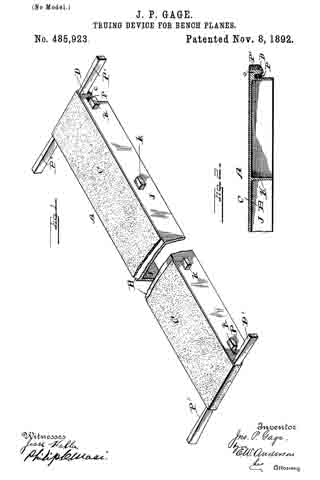
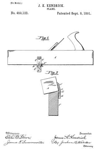
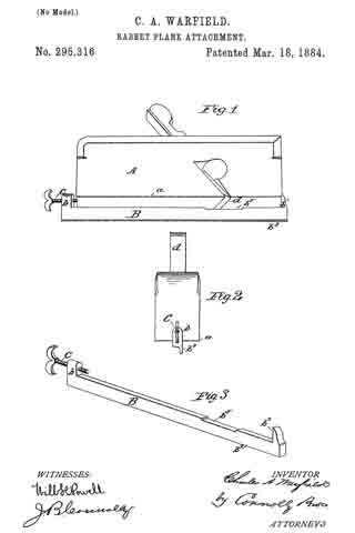
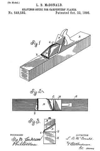
Figure 1 of the drawings is a representation of a perspective view of the guide applied. Fig. 2 is a plan view of same, and Fig. 3 is a front end view of same.

This invention has relation to certain new and useful improvements in shavings-guides for carpenters’ planes; and it consists in the novel construction and combination of parts, all as hereinafter described, and pointed out in the appended claims.

The object of the invention is to provide a carpenter’s plane with a simple and effective device of improved character for throwing the shavings from the plane off the bench.

Referring to the accompanying drawings, the letter A designates the stock, B the bit or iron, and C the wedge.

D is the guide, which constitutes the present invention in its combination with the stock in the manner presently described.

This guide consists of a piece of metal bent or arched upwardly over the opening D’ in the stock forward of the wedge, the transverse rear edge a of the metal resting against or in close proximity to the wedge and inclosing with the wedge said opening on three sides. The open side is at the longitudinal front face of the plane, and the guide is inclined downwardly from this side to the opposite side, which causes the chamber formed thereby to gradually increase in height from the back to the front longitudinal edge of the plane. By this arrangement the shavings forced up through the stock into this chamber readily clear themselves and are forced out of the open side of the guide and off the bench.

In some cases, in planes with metal stocks, I may prefer to cast the guide integral with the stock, or it may be a separate piece and be secured thereto by screws or othersuitable means. In the latter case a flange b is formed at the forward edge of the guide to receive the securing-screws, the rear longitudinal edge having, also, a flange c, which is secured to the rear longitudinal face of the stock.

When made separate, the guides will be in different sizes and may be readily applied to any of the ordinary styles of planes having either wooden or metal stocks.

Having thus described my invention, what I claim as new, and desire to secure by Letters Patent, is —

1. The combination with a plane stock and the wedge, of a shavings guide therefor, said guide comprising a plate portion attached to the stock and arched or bent over the opening therethrough and inclosing said opening, with the aid of the wedge, upon three sides, substantially as specified.

2. As a new article of manufacture, a shavings guide for carpenters’ planes, said guide comprising a plate portion arched or bent to adapt it to fit over and around the opening in a plane, and against the wedge thereof, and with said wedge inclose it upon three sides, and having danges for its attachment to a plane stock, substantially as specified.

In testimony whereof I anis my signature in presence of two witnesses.

LEWIS B. MCDONALD.

Witnesses:
JULIUS BRUNDT,
HENRY GRAMLING.

No. 507,378 – Plane-Guide (John McKnight) (1893)

[paiddownloads id=”494″]507378


UNITED STATES PATENT OFFICE.

_________________

JOHN McKNIGHT, OF FREDERICTON, CANADA.

PLANE-GUIDE.

_________________

SPECIFICATION forming part of Letters Patent No. 507,378, dated October 24, 1893.
Application filed September 24, 1892. Serial No. 446,794. (No model.)

_________________

To all whom it may concern:

Be it known that I, JOHN McKNIGHT, of Fredericton, in the Province of New Brunswick and Dominion of Canada, have invented a new and Improved Plane-Guide, of which the following is a full, clear, and exact description.

My invention relates to improvements in plane attachments, and the object of my invention is to produce a cheap and simple guide which may be attached to any kind of a plane, which is adapted to guide the plane so as to enable the edge of a board to be planed perfectly true and square, and which also may be adjusted so as to guide the plane in such a manner as to plane the edge of the board on any desired bevel.

To these ends my invention consists in a plane guide, the construction of which will be hereinafter described.

Reference is to be had to the accompanying drawings forming a part of this specification, in which similar figures of reference indicate corresponding parts in both the views.

Figure 1 is a perspective view of the guide embodying my invention, showing it attached to a plane and with the guide block swung upward to permit the plane to be used in the ordinary way for surface planing; and Fig. 2 is a perspective view of the plane guide and plane showing the bottom of the plane and with the guide block in position for use.

The same guide is provided with two jaws or clamping pieces 10 and 11 which are adapted to be placed parallel with each other and fastened to the top portion of the plane to permit of the lateral adjustment of the jaws so as to enable them to straddle one side of the plane, as described below; they have what is substantially a hinge connection at the top, the jaw 11 having an onset 12a with a tongue 12 thereon which enters the upper portion of the jaw 10. The jaws 10 and 11 are provided with central vertical slots 13 and 13a through which extends a clamping bolt 14 having a suitable nut on one end, and by tightening the nut the jaws may be held together and clamped firmly to the plane 15. When the jaws are to be applied to the plane, the jaw 11 is placed inside the plane, that is, in the top recess of the plane, and the jaw 10 on the outside, as shown in Fig. 1. The jaw 10 has a laterally extending offset 16 at the bottom, on which is hinged an outwardly swinging arm 17, which arm has an outward bend at its free end, as shown at 18. The hinge connection between the arm 17 and offset 16, is formed by the bolt 19, which bolt is provided with a thumb nut 20 and by tightening the nut the arm 17 may be held in any desired position in relation to the offset 16.

The bent end 18 of the arm 17 is slotted laterally, as shown at 21, so as to permit the adjustment of the fastening screw 22 which is held in the arm, and this screw serves to bind the guide block 23 to the arm. This guide block is also slotted longitudinally, as shown at 24, and consequently the block and arm may be brought to any necessary position in relation to each other, the adjustment being necessary to enable the attachment to be applied to any kind of a plane.

The guide block 23 has at the end and on one side, a smooth flat bearing flange 25, the flange at the side of the block being adapted to fit against the side or edge of a board, and one of the end flanges being adapted to strike against the edge of the plane bottom, as shown in Fig. 2. When the guide block 23 is swung downward and fastened with its upper end against the plane bottom, the block will be held at right angles to the bottom of the plane, and if a board is to be edged, the guide block is permitted to run upon the flat face of the board and the plane knife is brought upon the edge so that a perfectly true and square edge may be produced even by a novice.

If the edge is to be planed on a bevel, the arm 17 and block 23 are adjusted so as to extend at an obtuse angle to the plane bottom, and when brought to the desired angle the thumb nut 20 is tightened so as to hold the arm securely in place, and by permitting the guide block to run upon the surface of the board, the edge may be planed on any desired bevel.

From the foregoing description it will be seen that this device is very cheap and simple, and the parts of it may be cast. It will also be seen that by reason of its adjustability, the guide may be attached to planes of any size, and the plane may be made to edge a board so as to produce a square edge or a bevel edge.

Having thus described my invention, I claim as new and desire to secure by Letters Patent —

1. In a plane guide, the combination with jaws for attaching the guide to a plane, and an adjustable arm, on one of the jaws, of a guide block longitudinally and laterally adjustable on said arrn, substantially as described.

2. In a plane guide, the combination with jaws, of an arm adjustably connected to one jaw and provided with a lateral slot, a guide block provided with a longitudinal slot, and a binding screw or bolt passing through the slots of the arm and guide block, substantially as described.

3. A plane guide, comprising two slotted and hinged jaws, one of which is provided with an offset, a clamping bolt passing through the slots of the jaws, an adjustable arm carried by the said offset, and an adjustable guide block carried by the arm, substantially as described.

4. The herein described plane guide, consisting of the slotted and hinged jawsc10 and 11, the jaw 10 being provided with the offset 16, the clamping bolt 14, the arm 17 pivoted to the offset by the bolt 19 and nut 20 and provided with the lateral slot 21, the guide block 23 provided with the longitudinal slot 24 and flanges 25, and the screw 22 securing the block to the arm, as specified.

JOHN McKNIGHT.

Witnesses:
J. B. GUNTER,
S. H. L. WHITTIER.

No. 485,923 – Truing Device For Bench-Planes (John Porcius Gage) (1892)

[paiddownloads id=”488″]485923


UNITED STATES PATENT OFFICE.

_________________

JOHN PORCIUS GAGE, OF VINELAND, NEW JERSEY.

TRUING DEVICE FOR BENCH-PLANES.

_________________

SPECIFICATION forming part of Letters Patent No. 485,923, dated November 8, 1892.
Application filed March 31, 1892. Serial No. 427,209. (No model.)

_________________

To all whom it may concern:

Be it known that I, JOHN PORCIUS GAGE, a citizen of the United States, and a resident of Vineland, in the county of Cumberland and State of New Jersey, have invented certain new and useful Improvements in Truing Devices for Bench-Planes; and I do declare the following to be a full, clear, and exact description of the invention, such as will enable others skilled in the art to which it appertains to make and use the same, reference being had to the accompanying drawings, and to letters of reference marked thereon, which form a part of this specification.

Figure 1 of the drawings is a representation of the device and is a perspective view. Fig. 2 is a longitudinal section of same.

This invention relates to certain novel devices for truing up or facing off the working or face side of carpenters’ bench-planes; and it consists in the novel construction and combination of parts, as hereinafter specified.

The invention more particularly consists in providing an abrasive surface held upon a suitable support in such a manner that all parts thereof will in so far as possible lie in the same plane, so that by rubbing the working face of the plane over such surface said face will be left perfectly true and smooth, which is a necessary qualification for a tool of this character. For truing up wooden planes this abrasive surface consists in a strip of ordinary sandpaper arranged in the manner above specified, while with metal planes emery-paper is employed.

In the accompanying drawings I have illustrated a convenient and effective manner of arranging the abrasive material, which consists in providing an elongated frame or table A, formed from a heavy metal casting having the horizontal portion B, the surface of which is in so far as possible a true plane, and is supported by the integral vertical depending flanges J, reinforced at intervals by the transverse portions K. Along the lateral outer faces of the flanges J are projecting lugs k, located at intervals, by means of which the table may be rigidly held in a stationary position in a suitable block or support. Over the upper surface of the horizontal portion B is tightly stretched a strip of sand or emery paper C, which is made secure at its ends in such a manner as to insure against an endwise or lateral displacement. In the drawings I have shown this as effected by bringing the ends of the paper over the ends of the frame or table and under depending flanges c, between which flanges and the ends D of the table are driven wedges P. Tapered wedges P are also driven under the paper from opposite sides against the flanges c. Should the paper become slack, these wedges may be driven in a greater distance. The heavy casting forming the table or support forms an effective means for the purpose, in that it is free from any vibration and renders the operation of the device very satisfactory. It will be understood, however, that I do not desire to limit myself to any especial devices for holding the paper in place, as such devices may be varied without departing from the spirit and scope of this invention.

Having described this invention, what I claim, and desire to secure by Letters Patent, is —

The herein-described device for truing up the working faces of bench-planes and other articles, said device comprising a heavy oblong rectangular metal casting having a true upper horizontal surface and formed at its ends with the under transverse lugs and a strip or piece of material provided with an abrasive surface stretched tightly over the true surface of said casting, the ends of said strip or piece being extended over the ends of the casting and clamped in said under transverse lugs, substantially as specified.

In testimony whereof I affix my signature in presence of two witnesses.

JOHN PORCIUS GAGE.

Witnesses:
JOHN S. GAGE,
W. W. BENTHALL.

No. 469,688 – Attachment For Planes (Addison J. Ferris) (1892)

[paiddownloads id=”484″]469688


UNITED STATES PATENT OFFICE.

_________________

ADDISON J. FERRIS, OF EAST HAMPTON, MASSACHUSETTS.

ATTACHMENT FOR PLANES.

_________________

SPECIFICATION forming part of Letters Patent No. 469,688, dated March 1, 1892.
Application filed April 13, 1891. Serial No. 388,672. (No model.)

_________________

To all whom it may concern:

Be it known that I, ADDISON J. FERRIS, a citizen of the United States, residing at East Hampton, in the county of Hampshire and State of Massachusetts, have invented new and useful Improvements in Attachments for Planes, of which the following is a specification.

This invention relates or has reference to improvements in planes which are especially designed for finishing rabbeted portions of wood-work and which planes are provided with adjustable gages to accord with the depths of diderent rabbets; and the object of the invention is to improve the device for the purpose indicated, whereby the same may be most readily applied on the stock of almost any ordinary plane, and whereby when so applied it is capable of being most readily or conveniently and minutely adjusted, and when so adjusted it may be maintained against derangement, and also whereby all the parts forming the gage to be applied on the plane may be so united or engaged that even when not applied on the plane they are to all intents and purposes a single fixture, the components of which are not liable to detachment or loss.

The invention consists in the construction and combination of parts, all substantially as will hereinafter more fully appear, and be set forth in the claims.

In the accompanying drawings the present improvements are fully illustrated, Figure 1 being a side view of a plane with the gage applied thereon. Fig. 2 is a plan of the bottom of the plane and of the gage, while Fig. 3 is an end view and partial vertical section of the plane and gage, taken on line 3 3, Fig. 2, said parts being shown as in working relation to a rabbeted piece of stock as used fora door or window casing. Fig. 4 is a perspective view of a portion of the plane-stock, showing the same as recessed for the reception of the gage attachment; and Fig. 5 is a perspective view of the gage attachment removed from the plane.

In the drawings, A represents the gage attachment, which, as specially illustrated, consists of a carrier-plate a, provided at its upper end with an angularly-extended portion b, vertically bored, as at d, and said carrier-plate is vertically slotted, as at f which slot is open to the bottom of the plate. The vertical screw g passes freely through the said bore or perforation d and lies alongside of and within the said carrier-plate and is prevented against endwise movement relative to the plate by the fixed thumb piece or head h, above the part b and the collar or nut j below the same.

m represents the gage, which is necked or formed notched intermediately of its opposing edges, as at i, so that the middle of the gage part may be entered in the slot between the side portions of the carrier-plate a, so that a lug or extension at of the gage mlies inside of the plate a and, being bored and tapped, has an engagement with the screw.

It will be seen that, due to the construction of the parts substantially as above set forth, the gage-block has a movable and sliding engagement with relation to the edges of the slot forming the guideway therefor.

The plane-stock B is in its side recessed, as at k, said recess extending from a short distance from the bottom face of the plane-stock to the top thereof, and the said recess at its borders and at the top is provided with the rabbets or rests l l, so that the carrier-plate a may be let within and disposed flush with the sides and top of the stock, nothing projecting outwardly beyond the stock in any direction except the gage proper m and the operating thumb-head. The plate is secured to the plane-stock by the screws o o. On desiring to adjust the gage m so that it will be brought and firmly held on the side of the plane-stock at a greater or less distance from the bottom face of the plane, such may readily and positively be effected by simply turning the screw by its head more or less in the one or the other direction to accord with the depth of the rabbet in the material which is to be finished up.

I therefore claim —

1. The combination, with the plane-stock having the recess in its side, of the carrier-plate a, with the longitudinal slot f and provided with the angularly-extended member b, with the aperture d, the gage m, having the neck guided by the edges of said slotway and provided with the lug n, and the screw g, passed freely through said aperture d and, while freely rotatable, held against endwise movement and having a screw engagement with said lug, all substantially as and for the purposes set forth.

2. An attachment for planes, consisting of the carrier-plate a, having the slot f extending longitudinally from one end thereof and having the angular portion b, with the aperture d, the block having the notched edges i, which have a movable and sliding engagement with the borders of said slot, and said block comprising the gage m and the lug n, which latter has a screw-opening, and the screw g, loosely passed through the aperture h and provided with the thumb-head h and the collar j and having a screw engagement with the said lug n, substantially as deserihed, for the purpose set forth.

ADDISON J. FERRIS.

Witnesses:
WM. S. BELLOWS,
G. M. CHAMBERLAIN.

No. 466,494 – Beveling Attachment For Planes (Frank E. Hart) (1892)

[paiddownloads id=”481″]466494


UNITED STATES PATENT OFFICE.

_________________

FRANK E. HART, OF BROOKLYN, NEW YORK.

BEVELING ATTACHMENT FOR PLANES.

_________________

SPECIFICATION forming part of Letters Patent No. 466,494, dated January 5, 1892.
Application filed January 3, 1891. Serial No. 376,605. (No model.)

_________________

To all whom it may concern:

Be it known that I, FRANK E. HART, a citizen of the United States, residing in the city of Brooklyn, county of Kings, State of New York, have invented certain new and useful Improvements in Beveling Attachments for Planes, of which the following is such a full, clear, concise, and exact description as will enable others skilled in the art to which my invention appertains to make and use the same, reference being had to the accompanying drawings, forming part of this specification.

The object of my invention is to provide an attachment for a plane whereby the edge of a board, window-sash, door, or similar article may be reduced to the required angle and an accurate and predetermined bevel given without the aid of a square or other separate measure; and my invention consists in the improvements hereinafter more fully described, and pointed out in the claims.

In the drawings, Figure 1 is a view in elevation of an ordinary plane fitted with the improved attachment. Fig. 2 is an end view of the same, showing the plane in action upon a beveled surface. Fig. 3 is a plan view of end of plane with attachment connected, showing top of graduated segment. Fig. 4 is a side view of attachment unconnected, and Fig. 5 is a rear view of the same.

The plate A, having flanges a a’, maybe conveniently secured to the plane B by means of the binding-screw C, and pivoted to this plate are the adjustable guiding arms or bars D and E, extending downward from opposite sides. The arms D and E of course might, if desired, be secured directly to the body of the plane The arm D is preferably formed with a slotted graduated sector d, adapted to be secured by the binding-screw d’, whereby the said arm may be held at any desired angle to the lower surface of the plane, while the arm E is shown as provided with a slotted elbow e, which, moving upon and about the screw e’, permits the arm E to be brought parallel to the arm D and also to approach and withdraw from the same. The lower ends of the guiding-arms D and E are, moreover, preferably provided with flanges d2 e2, which are shown as slightly beveled or inclined, giving thus a greater guiding-surface, while at the same time allowing the necessary oscillation and freedom in the movement of the plane. Further, the flange d2 forms a convenient rest for the finger of the artisan.

It is readily seen that when the guiding-bars D and E are adjusted to any position other than the perpendicular the plane will be made to bear unevenly, cutting more on one side than the other, until A the surface to be smoothed or reduced becomes parallel to the bottom of the plane and its slant or bevel corresponds with the inclination of the guiding-arms.

Having thus fully described my invention, what I claim as new, and desire to secure by Letters Patent, is —

l. In combination with a plane, guiding-arms pivoted thereto and extending downward from opposite sides, said arms being adapted to be secured at an angle, whereby the plane is inclined and made to bear unevenly until the surface acted on is smoothed or reduced to the slant or bevel desired, substantially as set forth.

2. In combination with a plane, a plate adapted to be secured thereto and provided with adjustable guiding-arms extending downward from opposite sides, whereby the plane is inclined and made to bear at an angle, substantially as and for the purpose set forth.

3. In combination with a plane, a plate adapted to be secured thereto, and guiding-arms pivoted to said plate and extending downward from opposite sides, the said arms being provided at their lower ends with beveled fianges, substantially as and for the purpose set forth.

4. In combination with a plane, the flanged plate B and guiding-arms D and E, having graduated sector d and slotted elbow e and flanges d2 and e2, all arranged and secured substantially as described.

FRANK E. HART.

Witnesses:
PERCY GRIFFITH,
WM. J. WINBERG.

No. 459,122 – Plane (James K. Kendrick) (1891)

[paiddownloads id=”478″]459122


UNITED STATES PATENT OFFICE.

_________________

JAMES K. KENDRICK, OF GERMANTOWN, CALIFORNIA.

PLANE.

_________________

SPECIFICATION forming part of Letters Patent No. 459,122, dated September 8, 1891.
Application filed March 20, 1891. Serial No. 385,803. (No model.)

_________________

To all whom it may concern:

Be it known that I, JAMES K. KENDRICK, a citizen of the United States, residing at Germantown, in the county of Colusa and State of California, have invented certain new and useful Improvements in Planes; and I do declare the following to be a full, clear,and exact description of the invention, such as will enable others skilled in the art to which it appertains to make and use the same, reference being had to the accompanying drawings, and to the letters of reference marked thereon, which form a part of this specification.

My invention has relation to improvements in plane-guides; and it consists in the construction, novel combination, and adaptation of parts hereinafter described and claimed.

The invention will be fully understood from the following description and claim when taken in conjunction with the annexed drawings, in which —

Figure 1 is a side elevation of a plane provided with my irnproved guide; and Fig. 2 is an end elevation of the same in conjunction with a piece of wood, illustrating the relative position of the plane and guide with respect to each other and the wood when itis desired to bevel one corner of the latter.

Referring by letter to the said drawings, A indicates a jack-plane, which may be of any approved construction, and B indicates the bit thereof. Permanently connected to the left-hand side of the plane by screws C’ or the like is the flat stationary section C of my improved guide, the lower portion of which is forked and depends below the bottom of the plane, as illustrated.

D indicates the adjustable section of my improved guide, which is also flat, and has its upper portion tongued, as illustrated, to take between the depending fork branches of the stationary section, to which it is pivotally connected by a transverse bolt E, which takes through the fork branches of the stationary section and the tongue portion of the adjustable section, and has one of its ends threaded to receive a wing-nut E’, which serves to secure the bolt in position. By this construction of guide, which comprises but four parts and may be made of hard wood or the like, it will be seen that a cheap and efficient guide is afforded without rnaterially increasing the weight of the plane, and by the provision of the wing-nut E’ it will be readily perceived that the adjustable section may be readily removed and another section placed in position when desirable.

Having described my invention, what I claim, and desire to secure by Letters Patent, is —

The combination, with a plane, of the guide consisting of the flat section C, permanently attached to the side of the plane and having its lower portion forked, the flat adjustable section D, having its upper portion tongued or reduced to take between the fork branches of the section C, the bolt taking through the fork branches of the section C and the tongue of section D and having its end threaded, and a wing-nut mounted on the threaded end of said bolt, substantially as specified.

ln testimony whereof I affix my signature in presence of two witnesses.

JAMES K. KENDRICK.

Witnesses:
P. H. CLARK,
L. H. HILL.

No. 441,758 – Device For Setting The Edges Of Plane-Bits (Edrick Gowdy) (1890)

[paiddownloads id=”469″]441758


UNITED STATES PATENT OFFICE.

_________________

EDRICK GOWDY, OF ANSONIA, CONNECTICUT.

DEVICE FOR SETTING THE EDGES OF PLANE-BITS.

_________________

SPECIFICATION forming part of Letters Patent No. 441,758, dated December 2, 1890.
Application filed April 10, 1890. Serial No. 347,366. (No model.)

_________________

To all whom it may concern:

Be it known that I, EDRICK GOWDY, a citizen of the United States, residing at Ansonia, in the county of New Haven and State of Connecticut, have invented certain new and useful Improvements in Devices for Setting the Edges of Plane-Bits and other Tools; and I do hereby declare the following to be a f ull, clear, and exact description of the invention, such as will enable others skilled in the art to which it appertains to make and use the same.

My invention has for its object the production of a simple and inexpensive device which may be readily carried about in a tool-box, and which will act to turn forward slightly the edges of plane-bits and other tools. I have found in practice in planing all classes of wood, it being particularly true in the case of knotty close-grained woods, that by turning forward the edge of the bit of the plane I can secure very much better results in the way of a line smooth finish, avoid all danger of chipping out, and can retain the plane-bit sharp and in good condition for use much longer than when the edge is left to project downward in a line with the front of the blade in the usual manner; and in order that I may set the edges of plane-bits without inconvenience and at any time I have devised the simple and novel tool of which the following description, in connection with the accompanying drawings, is a specification, numbers being used to denote the several parts.

Figure 1 is a perspective of my novel tool, showing also a portion of a plane-bit at the angle at which it is passed over the turning-piece; Fig. 2, a longitudinal section of my novel tool, showing the turning-piece in elevation. Fig. 3 is an elevation on a greatly-enlarged scale of the lower end of a plane-bit, showing the edge turned forward as after it has been acted upon by my novel tool; and Fig. 4 is a section similar to Fig. 2, showing a slightly-different mode in which I have carried my invention into effect.

1 denotes a block, preferably made of wood, which is provided with a hole 3, bored into the block from either end near the top of the block and adapted to receive a round piece of metal 4, which I term a “turning-piece.” This turning-piece is preferably made of chilled steel, and is made slightly larger than the hole, so as to require to be driven therein and remain firmly wherever it is placed. It will be noticed that hole 3 is made near enough to the top of the block so that the upper portion of the hole is open. This permits the rounded surface of the turning-piece after it is driven in to project slightly above the surface of the block, as is clearly shown in the drawings. In practice I preferably drive a plug 2 into the hole after the turning-piece has been driven in and smooth it off level with the top and end of the block, so as to give a neat finish to the tool. For convenience in driving the turning-piece out, should it be required, I preferably provide a hole 5, which extends into hole 3 from the other end of the block. Should the turning-piece become worn or nicked in use, it may readily be driven out, given a partial rotation to place another portion of the rounded surface in operative position, and then driven back to place and the plug driven in after it.

In use, after sharpening a plane-bit or other blade, the operator takes the blade firmly in his hand, holding it at about the angle indicated in the drawings, and passes it backward and forward over the turning-piece one or more times, as may be required. The action of the portion of the turning-piece lying above the surface of the block will be to turn the cutting-edge forward slightly, as shown in Fig. 3. In Fig. 4 I have shown the block as provided with a transverse undercut groove 7, the undercut side of said groove being the forward side, which is made perfectly straight, but is inclined downward and inward. The hole to receive the turning-piece is lower down in the block and is intersected by the groove, the rounded surface of the turning-piece lying about the same distance above the bottom of the groove that it does above the surface of the block in the other form. In using this form the operator passes the blade, the edge of which is to be turned through the groove and over the surface of the turning-piece one or more times in the same manner as in using the other form.

In order to hold the block firmly in place and make the tool convenient in use, I provide two or more sharpened prongs 6, which project downward from the bottom of the block to engage a work-bench or plank and hold the block firmly in place when it is desired to use the tool.

Having thus described my invention, I claim —

1. A tool for setting cutting-edges, consisting of a, block having a, rounded turning-piece driven therein, the upper portion of which extends slightly above the surface of the block, so that a, cutting-edge passed over the surface of the block will engage the rounded surface of the turning-piece and be turned slightly forward, as and for the purpose set forth.

2. A tool for setting cutting-edges, consisting of a block having a rounded turning-piece driven therein and extending slightly above the surface thereof, and prongs upon the under side thereof, whereby the block may be held in place in use.

In testimony whereof I afflx my signature in presence of two witnesses.

EDRICK GOWDY.

Witnesses:
CHAS. S. WEEKS,
Mrs. E. GOWDY.

No. 367,071 – Gage For Wood-Working Planes (Edward B. Shepardson) (1887)

[paiddownloads id=”423″]367071


UNITED STATES PATENT OFFICE.

_________________

EDWARD B. SHEPARDSON, OF GREENFIELD, MASSACHUSETTS.

GAGE FOR WOOD-WORKING PLANES.

_________________

SPECIFICATION forming part of Letters Patent No. 367,071, dated July 26, 1887.
Application filed April 6, 1887. Serial No. 233,912. (No model.)

_________________

To all whom it may concern:

Be it known that I, EDWARD B, SHEPARDSON, a citizen of the United States, residing at Greenfield, in the county of Franklin and State of Massachusetts, have invented certain new and useful Improvements in Gages for Wood-Working Planes; and I do hereby declare the following to be a full, clear, and exact description of the invention, such as will enable others skilled in the art to which it appertains to make and use the same.

This invention is an improvement in gages as attachments to woodworking planes; and it has for its object to provide an attachment to planes of hollow metal construction, one part of which is adjustable about an axis of motion to any required angle with reference to the bottom surface of the plane to which said gage is attached, so that a guide will be formed to fit against one surface of the material and slide against the same as the bottom of said plane rides over an edge of said material, cutting the same and forming an angle with reference to anotherside of said material greater or less than a right angle.

Mechanics who are in the habit of using wood-working tools are familiar with the difficulties encountered in beveling the edge of a board where the eye and feeling or judgment alone are depended upon in making the required angle. It is desirable, in view of such difficulties, that a good and simple device be provided, so that the operation of beveling may be only mechanical. Such devices have been invented, I am aware, as applicable to planes the stocks of which are of wood. My gage is intended to be applied to a plane the stock of which is of metal. My gage is formed, in the main, of two pieces of metal hinged together. One of said sections consists of a horizontal bar having at each of its two ends projections of T form, the bar, with its two ends, forming an H, as seen from the outside. Each of the T ends is bent inward nearly at right angles. The upper of these bent ends forms lugs for clamping-screws, and the lower of said bent portions is slotted and connected by a bracing-bar. The lower part of the gage is composed of a bar of U shape, the inner plane-surface of which is smooth, and the ends of said bar form tongues, which enter the slots in the upper portion of said gage where the two said parts are hinged together. Bifurcated pieces, forming clevises, project outward from the H -bar and the U -bar, and in these are pivoted or hinged screw-threaded nuts. A right-and-left screw provided with a thumb-piece on its center engages these nuts, and when operated increases or diminishes the angle between the two parts of the gage.

In my drawings, Figure 1 is an elevation of the gage as seen from the outside. Fig. 2 is a transverse vertical section of the same, showing the application of the gage to a plane and the relation of the latter to a piece of material being beveled.

Similar reference-letters indicate like parts in both of the figures.

Referring to the drawings, A is the horizontal bar of the upper portion of the gage, and B B’ are the T ends ofthe same, provided with bent portions a a’ b b’, the latter of which are connected by the strengthening-bar C.

d d’ are slots formed in the bent ends b b’, which receive the tongues e e’ of the lower portion of the gage.

D is the lower portion of the gage, formed as previously stated, the tongue ends of which are hinged in the slots of the T-pieces B B’. The long bar of the upper portion of the gage and the curved bar of the lower portion of the same have projecting from their centers outward bifurcated pieces or clevises E E’. In the outer ends of these clevises are pivoted swivel-nuts f f’, adapted to receive the right and left ends of the double screw F.

The bent T ends a a’ have screw-threaded openings to receive the screws G G’, the clamping ends of which latter may be threadless.

In applying this gage to a plane I place the bent portions a a’ on one of the side walls, with the long bar A resting against the outside of said wall and the clamping-screws — not yet driven down — against the inside of the same. The gage should be so placed upon the plane that one of the clamping-screws shall be in front of the handle and the other rearward of the same. When the screws are driven down to place, they impinge upon the bottom plate of the plane and draw the bent ends b b’ of the gage up against the bottom surface of said plane, and the gage is thus firmly held to place.

It may be observed that the interior angles between the T-pieces and portions a a’ are less than right angles, so that the screws when driven home find their places in the angle of the plane formed by the inner surface of the bottom and the inner surface of the said side wall. The gage being thus firmly secured to the plane, when the angle of the bevel to be made is determined the lower or U -shaped bar of the gage is moved about its axis by the right-and-left screw G G’ until the proper angle is formed. The gage is now applied with the plane to the piece of material to be planed in such a manner that the inner surface of the U-shaped bar rests against one side of said material and the bottom surface of the plane upon the edge of the same to be beveled.

The operator has only to keep the gage upon the guiding-surface of the material as he operates the plane to insure accurate work.

Having thus described my invention, whatl claim as new, and desire to secure by Letters Patent, is —

In a gage for use with wood-working planes, the combination, with the upper portion provided with clamping-screws, a swivel-nut, and jaws or bearings for the same, of the lower portion of said gage hinged to the said upper portion, provided with a swivel-nut and jaws or bearings for the same, and the right-and-left screw engaging said swivel-nuts to adjust the two portions, the one with reference to the other, as and for the purpose set forth.

In testimony whereof I affix my signature in presence of two witnesses.

EDWARD B. SHEPARDSON.

Witnesses:
JAMES S. GRINNELL,
FRANKLIN G. FESSENDEN.

No. 316,296 – Plane (Louis C. Rodier) (1885)

[paiddownloads id=”391″]316296


UNITED STATES PATENT OFFICE.

_________________

LOUIS C. RODIER, OF DETROIT, MICHIGAN.

PLANE.

_________________

SPECIFICATION forming part of Letters Patent No. 316,296, dated April 21, 1885.
Application filed November 8, 1884. (Model.)

_________________

To all whom it may concern:

Be it known that I, LOUIS C. RODIER, of Detroit, county of Wayne, State of Michigan, have invented a new and useful Improvement in Planes; and I do hereby declare the following to be a full, clear, and exact description of the same, such as will enable others skilled in the art to which it pertains to make and use it, reference being had to the accompanying drawings, which form a part of this specification.

My invention relates to bench-planes, and more particularly to metallic bench-planes, and has for its object, first, the combination, with a stock, of an improved knife holder or carriage provided with devices for operating the same and adjusting the knife to secure the desired depth of cut; second, the combination, with a stock, of a novel attachment for holding a toothing iron or scraper; third, to combine in a bench-plane the said knife-holder and said attachment for toothing irons and scrapers, said attachment being removable, so that the knife or bit may be removed and the toothing or scraper attachment be engaged with the stock,or said attachment be removed and the knife inserted, the plane being thus readily convertible for various uses; and, fourth, it consists in the general construction and arrangement of the novel devices, hereinafter described, and more particularly pointed out in the claims.

I carry out my invention as follows:

In the drawings, Figure 1 is a longitudinal section of a jack-plane, showing the knife-holder in position with the knife or bit in place. Fig. 2 is a similar section showing the toothing or scraper attachment in position. Fig. 3 is a modihcation adapting features of the device more particularly for a smoothing-plane or block-plane. Fig. 4. is a separate view of the toothing iron and scraper attachment. Fig. 5 is a cross-section along the line at x y, Fig. 6. Fig. 6 is a view showing the knife-carriage and its operating devices. Fig. 7 is a side elevation.

A represents the stock provided with a throat, a.

B is the knife-rest, which may be constructed of any suitable form or pattern, and adapted to hold the knife on a proper incline. It may be provided with ears b extending upward at the side of the knife, or these ears may be dispensed with, as shown in Fig. 3. This knife-rest is provided with a rearwardly-extending arm, b’, provided with a screw-orifice, b2, (shown in Fig. 1,) or otherwise adapted to receive the head of a screw, and to receive its force, as shown in Fig. 3. I also prefer to construct the knife-rest, when applied to jack-planes, with an extended knife-brace, b8. This knife-rest may be secured within the walls of the stock and suitably adjacent to the throat in any suitable manner, as sh own in Fig. 5. The knife-rest is screw-tapped to receive the screws b3 and b4 These screws are preferably constructed with rounded ends to engage in corresponding sockets, a’ and a2, in the base of the stock, the construction being such that the knife-rest may have a movable or slightly-vibratory movement, so that either side of said knife-rest may be elevated or depressed to more effectually adjust the knife to cut evenly across its entire edge.

C is a spring engaged with the knife-rest at one end, as shown at c, and under the arm b’
and upon a raised bed, A’, upon the base of the stock.

D is a bridging constructed preferably integral with the stock, under which the spring is extended, said bridging also preferably provided with a screw, d, adapted to bear upon the spring to give it greater tension upon the knife-rest. I do not limit myself to any special construction of this bridging.

The bed A’ is screw-tapped, as shown at a3, to receive a screw, B’.

B2 is a thumb-nut adapted to operate upon said screw, and to bear upon the rear of the arm b’ to tilt the knife-rest to any desired angle.

E is a knife-clamp provided with hooked arms e, adapted to engage over the ears b of the knife-rest, said ears being suitably cut away at their rear edge to receive said hooked arms, so that the one will be flush with the other, as shown in Fig. 7. The side walls of the stock are preferably cut away slightly to receive said ears and arms also, as shown also in Fig. 7.

E’ is a thumb-screw tapped into said clamp and adapted to tighten and hold the knife upon the knife-rest beneath. F is the knife. The clamp may have, however, any suitable engagement with the knife-rest.

When the thumb-nut B2 is forced down upon the arms b’ of the knife-rest, the effect will be to tilt the knife-rest and so adjust the knife relatively to the throat, said rest being adapted to have a slight longitudinal vibratory motion upon the ends of the screws b3 and b4, as well as a vibratory motion across the stock, while the pressure of the thumb-screw E clamps the lower part of the knife-clamp upon the knife near its cutting-edge, so that the knife is held firmly between said clamp and the knife-rest. The knife is thus readily held in position. The knife may be put in place by loosening the clamp, which is then raised to disengage its hooked arms from the ears of the knife-rest. When the knife is in place, the clamp is forced down so that its hooked arms shall be engaged over the ears of the knife-rest, and the thumb-screw may be tightened thereon when the cutting-edge of the knife has been properly adjusted.

As shown in Fig. 3, instead of providing the knife-rest with the screws b3 and b4, having rounded ends, forming the bearings of said rest, I may construct said rest with integral bearings or lugs b5, answering the same purpose as the screws in Fig. 5, the only difference being that the knife-rest cannot readily be adjusted across the stock as can be done, as already described, where the screws b3 and b4 are employed. So, also, instead of engaging the spring in the knife-rest, as shown in Figs. 1 and 2, the tension may be secured in essentially the same way by constructing the arm b with a cross-bar, as shown at b6, in which case the end of the spring may be engaged under the bridging, being passed over said cross-bar, as shown in Fig. 3, the tension being secured by means of the screw B’. By operating said screw the knife-rest may be tilted, as before, to secure the desired adjustment of the knife relative to the throat to make it cut more or less, as may desired.

To insure the proper location of the knife upon the rest and relatively to the throat, I also prefer to construct the knife with an orifice, f adapted to engage over a lug, G, which may be adjustably located beneath it either upon the spring, as shown in Fig. 3, or upon an arm, b7, integral with the knife-rest. This device when the lug is once adjusted properly will permit the ready engagement of the knife relatively to the throat, and when the knife becomes worn the lug can be adjusted to compensate for the wear.

H represents my improved toothing iron or scraper attachment, substantially as shown in Fig. 2, consisting of a suitable front clamp, H’, and rear clamp, H2, the front clamp being preferably provided with engaging-arms h, adapted to engage upon the rear clamp, said clamps provided with thumb-screws h and h2 to bind the toothing iron or scraper H3 between said clamps, as shown in Fig. 2. By means of the said screws the toothing-iron may be readily engaged in said clamps or removed thereupon for the insertion of the scraper, as desired, said clamps forming a holder or harness for the cutting-tool.

The rear clamp is provided with a wing, h3, constructed and arranged to be seated upon the knife-rest B. The knife-clamp E is then clamped upon the wing, the knife F being removed, which holds the said attachment firmly in place. It is evident that this attachment may be readily removed and the knife inserted, and vice versa.

Instead of engaging the wing h3 upon the knife-rest by means of the knife-clamp already described, the wing itself may be provided with engaging-shoulders h4, similar to the hooked arms e of said clamp, and serving a similar purpose.

I design to provide the stock of the plane with a scale-bar or measure, as shown in Fig. 7. The spring serves to take up any slack which may result in the adjustment of the knife-rest by means of the screw B’.

In the jack-plane, as shown in Figs. 1 and 2, the spring is engaged with the knife-rest forward of the bearings b3 and b4. In Fig. 3 the spring is engaged with the rest in the rear of the bearings, the spring operating simply in a reverse manner to take up the slack.

Instead of a screw, B’, a suitable cam may be employed. I would have it understood that I do not limit myself to the screw alone to secure this proper adjustment.

I do not limit myself to the definite and precise construction of the parts H’ and H2 of the attachment, as shown, nor providing the part H2 with a wing, h3, as they may be of any suitable construction to removably hold the toothing iron or scraper suitably in position in the stock.

What I claim is —

1. The combination of a plane-stock, a knife-rest provided near its lower end with a support which permits the rest to be tilted in the direction of the length of the stock and also transversely thereto, a spring to exert an upward pressure upon the rest, and means to regulate the longitudinal tilting of the rest, substantially as described.

2. The combination of a plane-stock, a knife-rest, screws passed through said rest near opposite sides thereof and bearing against said stock to permit the rest to be tilted in the direction of the length of the stock and transversely thereto, a spring to exert an upward pressure upon the rest, and means to regulate the longitudinal tilting of the rest, substantially as described.

3. The combination of a plane-stock, a knife-rest, screws passed through said rest near the opposite sides thereof and bearing against said stock to permit the rest to be tilted in the direction of the length of the stock and transversely thereto, a spring to exert an upward pressure upon the rest, means to regulate the tension of said spring, and a screw to regulate the longitudinal tilting of the rest, substantially as described.

4. The combination of the plane-stock, the knife-rest, a support under the rest, a lug, G, supported by and capable of sliding longitudinally on the support and adapted to engage and move with a knife, a knife-clamp above the rest, and a screw engaging a screw-socket in the clamp for holding the knife upon the rest, substantially as described.

5. The combination, with a metallic plane-stock, of a removable toothing iron or scraper composed of two clamps provided each with a clamping-screw, one of said clamps being provided with a wing to engage with a knife-rest on the stock, substantially as described.

6. The combination, with a plane-stock provided with a knife-rest and knife-clamp, of a removable toothing iron or scraper attachment consisting of front and rear clamps constructed and arranged to be engaged with each other and provided with clamping-screws, said rear clamp provided with a wing, h3, adapted to be engaged upon the knife-rest, the construction being such that said attachment may be removed and the knife be clamped upon the rest, and vice versa, substantially as described.

In testimony whereof I sign this specification in the presence of two witnesses.

LOUIS C. RODIER.

Witnesses:
N. S. WRIGHT,
W. B. O’DOGHERTY.

No. 295,316 – Rabbet-Plane Attachment (Charles A. Warfield) (1884)

[paiddownloads id=”359″]295316


UNITED STATES PATENT OFFICE.

_________________

CHARLES A. WARFIELD, OF PHILADELPHIA, PENNSYLVANIA.

RABBET-PLANE ATTACHMENT.

_________________

SPECIFICATION forming part of Letters Patent No. 295,316, dated March 18, 1884.
Application filed September 18, 1883. (No model.)

_________________

To all whom it may concern:

Be it known that I, CHARLES A. WARFIELD, a citizen of the United States, residing at the city of Philadelphia, in the county of Philadelphia and State of Pennsylvania, have invented certain new and useful Improvements in Rabbet-Plane Attachments; and I do hereby declare the folioiving to be a full, clear, and exact description of the invention, reference being had to the accompanying drawings, which form part of this specification, in which —

Fignre 1 is a perspective of a plane with my attachment applied thereto. Fig. 2 is an end view, same parts as Fig. 1. Fig. 3 is a perspective of attachment.

My invention has for its object to provide a gage or regulating attachment for a rabbet-plane, whereby the width or depth of at rabbet cut may be controlled without employing a marker or equivalent device. My attachrnent consists of a bar provided with means for attaching it adjustably to the face of a common plane or rabbet-plane, forming a guide or gage therefor, substantially as hereinafter fully set forth.

Referring to the accompanying drawings, A represents a common rabbet-plane, to which my attachment is applied. B represents the attachment, consisting of a bar, preferably of metal, with lugs or flanges b b’ at either end. One of these lugs is serrated, as shown at b2, on its inner side, while the other lug has a screw or equivalent lever, or other securing appliance, by which it is made fast to the plane. When the screw C is turned in, it draws the log b’ against the opposite end of the plane, and so holds the attachment firmly on the latter. One side of the attachment constitutes a straight-edge, b3. The other side may be curved or of any desired configuration.

The attachment is adjusted on the face of the plane, with the straight-edge b3 at the same distance from the edge a of the plane as will equal the depth or width of the rabbet required to be cut. The plane is then ready for use. To cut rabbets of different widths or depths, the attachment must be correspondingly adjusted, such adjustment being very readily effected.

As will be seen, the attachment requires no change to be made in the stock of an ordinary plane, and when removed permits the use of the latter in its ordinary manner.

To prevent the bit d of the plane from coming in contact with the attachment, the latter should have a transverse groove, as shown at b5.

I am aware that it is not new, broadly, to provide a plane with an adjustable guide or gage for the purpose of cutting shelved or channeled sufaces; but such as I have any knowledge of have required a special adaptation of the plane to the purposes of the guide. I therefore do not broadly claim an adjustable rabbeting attachment, but limit myself to a guide of such a construction that it may be applied to any ordinary plane by simply clamping the attachment in place.

What I claim as my invention is —

The rabbet attachment for planes herein described, consisting of bar B, having its upper or inner surface flat and transversely grooved, and provided with lugs b b’ and a screw, C, or equivalent means for securing said attachment to the plane, substantially as shown and set forth.

In testimony that I claim the foregoing I have hereunto set my hand this 7th day of September, 1883.

CHARLES A. WARFIELD.

Witnesses:
LISLE STOKES,
WILL H. POWELL.

No. 191,393 – Improvement In Bench-Planes (Watson Wood) (1877)

[paiddownloads id=”278″]191393


UNITED STATES PATENT OFFICE.

_________________

WATSON WOOD, OF CHELSEA, MASSACHUSETTS.

IMPROVEMENT IN BENCH-PLANES.

_________________

Specification forming part of Letters Patent No. 191,393, dated May 29, 1877; application filed February 26, 1877.

_________________

To all whom it may concern:

Be it known that 1, WATSON WOOD, of Chelsea, in the county of Suffolk and State of Massachusetts, have invented an Improvement in Bench-Planes, of which the following is a specification:

In the accompanying drawing, Figure 1 represents a side view of a plane, partly in section, to show my improved oiling attachment; and Fig. 2 is a top view of the same.

Similar letters of reference indicate corresponding parts.

The invention has reference to an oiling attachment to iron or iron-faced planes, by which the objectionable sticking or friction of the same on wood is obviated; and the invention consists of an iron or iron-faced plane, having an oil-receptacle and feed device in front of the cutting-iron.

In the drawing, A represents a plane of any approved construction, being either entirely of iron or of wood with an iron face. A small hole, a, is drilled through the face of the plane in front of the cutting-iron and in the center of the face. This hole is connected, either by a small tube or directly, with an oil-receptacle, B, that may be either cast on the plane inside of the knob which is generally used as a handle, or otherwise attached to the same. The oil-receptacle B is closed by a knob, G, that is secured or otherwise applied in air-tight manner thereto. A wick or piece of soft leather is arranged at the inside of the receptacle and in the feed-hole et, so as to prevent the oil from being fed too fast on the face of the plane. The wick or other device admits only the escape of a quantity of oil sufficient to allow the iron-faced plane to run smoothly and easily over the wood, giving the iron face sufficient lubrication to destroy the friction or sticking of the same on the wood without greasing the work or the hands of the person using the plane.

When the plane is not in use no oil will escape, and, as no air can get in, it will last for a long time, and not gum at all. The face of the plane, being always oily, will not rust, nor will the iron rust, as the shavings that are cut by it supply a small quantity of grease to it, which leaves the iron in a good condition for any length of time, the oil-trap forming thus a useful attachment to the plane that facilitates the working with iron-faced planes.

I am aware that it is not new to set a soap-stone in front of a plane-iron; but

What I claim is —

The combination of plane A, having hole a, and the oil-reservoir B, the two connected directly or by tube with each other, substantially as and for the purpose specified.

WATSON WOOD.

Witnesses:
FRANK T. WARE,
EBEN HUTCHINSON.

No. 167,943 – Improvement In Plane-Guides (Walter S. Shipe) (1875)

[paiddownloads id=”254″]167943


UNITED STATES PATENT OFFICE.

_________________

WALTER S. SHIPE, OF MINERVA, OHIO.

IMPROVEMENT IN PLANE-GUIDES.

_________________

Specification forming part of Letters Patent No. 167,943, dated September 21, 1875; application filed August 14, 1875.

_________________

To all whom it may concern:

Be it known that I, WALTER S. SHIPE, of Minerva, in the county of Stark and State of Ohio, have invented an Improvement in Plane-Guides, of which the following is a specification:

In the accompanying drawing, Figure 1 represents an end view of my improved plane-guide, and Fig. 2 a side view of the same.

Similar letters of reference indicate corresponding parts.

My invention has for its object to so improve the plane-guide for which a patent has been granted to me under date of January 6, 1874, and numbered 146,208, that it will work more steadily and accurately, and be readily set to any desired angle.

The invention consists, mainly, of a recessed handle-extension of the yoke part in connection with a slotted arc-piece of the guide-strip connecting plate, the arc-piece being pivoted to the yoke, and set by a clamp-screw thereto. A wire key with bent end is inserted into a hole of the guide-strip for being readily available for turning the clamping-screw nuts.

In the drawing, A represents a plane, to which the yoke B is attached in the customary manner by a clamping-screw at one end, and flanged side extensions at the opposite end. The yoke B is cast at the end below the flanges with a handle-extension, E, that is centrally recessed tor the slotted arc-piece D, which forms, with its guide-plate D1, the connection with the guide-strip C. The slotted arc D extends at right angles from guide-plate D1, and is inserted and pivoted at its center in the handle-extension E. A set-screw, E’, passes through the perforations of the handle E and the slot of the arc-piece for the purpose adjusting the sliding arc to any required angle. The outer circumference of the arc-piece D is graduated, so that the same may be directly set with the guide-strip C to any required degree of inclination toward the plane. The guide-plate D1 is slotted and adjusted in a recess of the guide-strip C, nearer to, or farther from, the plane by a set-screw, D2. A key, F, of strong wire, with bent end is inserted into a socket-hole of guide-strip C, being slightly curved at its longer part to be retained there in with a certain tension without falling out, the shorter bent end serving as handle to withdraw it from the guide-strip. The wire key F is inserted into perforations of the heads of the set-screws, so that they can be easily loosened or tightened, while the key may be securely put away into the socket-hole of the guide-strip without getting lost. The key is thus always at hand tor use for setting the plane-guide, which is steadily and firmly adjusted in the handle-extension or socket-piece of the yoke.

Having thus described my invention, I claim as new and desire to secure by Letters Patent —

The combination, with a guide-strip, C, of plane-clamping yoke B, having recessed extension E, the pivotted slotted arc-piece D, and the clamp-screw E’, as and for the purpose specified.

WALTER S. SHIPE.

Witnesses:
JOHN BREIDENSTEIN,
A. N. BOORY.

No. 148,090 – Improvement In Bench-Planes (Quartus Rice) (1874)

[paiddownloads id=”226″]148090


UNITED STATES PATENT OFFICE.

_________________

QUARTUS RICE, OF WASHINGTON, DISTRICT OF COLUMBIA.

IMPROVEMENT IN BENCH-PLANES.

_________________

Specification forming part of Letters Patent No. 148,090, dated March 3, 1874; application filed August 20, 1873.

_________________

To all whom it may concern:

Be it known that I, QUARTUS RICE, of Washington, District of Columbia, have invented an Improvement in Bench-Planes, of which the following is a specification:

Figure 1 is a vertical longitudinal section of a carpenter’s or wood-worker’s bench-plane. Fig. 2 is a plan view of the same.

The nature of this invention consists, first, in the combination of an oil-vessel with the plane, to be operated automatically by the working of the plane; and, secondly, in a presser and cap in one device, constructed and operated as hereinafter more particularly described.

A is a vessel to hold oil. The oil-vessel A has two covers, represented, respectively, by the letters d and e. d is of rigid material. e is elastic, and capable of vibration. f is an iron strap, to which the handle of the plane is fastened, and which is also made fast to the plane at g, and is so constructed that the end y has a slight vibration by pressure on the handle m. b is a tube, through which oil is poured into the vessel A. It is also connected at c with the cover e, and made to slip freely through the cover d, and connect with the strap f at y, so that the vibration of the strap f is communicated to the cover e, and thus the vessel A is alternately contracted and enlarged, and, as the vessel keeps filled with air, the contraction forces the oil out through the aperture at h to the face of the plane, as desired. a is a stopple for the tube b. O is a presser, to hold the cutting-bit firmly in place, and also serves as a cap for the cutting-bit. P is a thumb-screw, for regulating the distance of the cap from the edge of the cutter, by which the frame F, carrying the presser-cap O, is turned upon its pivots o’ o’ in the sides of the plane, while the cap also moves upon the pivots o” o”, by which it is hung to the frame F, and is adjusted to the cutting-bit, so as to press firmly thereon, while the distance from the cutting-edge is also adjusted.

I am aware that there are pressers similar to this, but am not aware of any which act as cap and presser, and regulated in the manner herein described.

I claim as my invention —

1. An oil-vessel, in combination with carpenter’s or wood-worker’s bench~planes, so constructed, in connection with other parts of the plane, that by working the plane the oil will be forced to the face of the plane, substantially as and by the means described.

2. The presser-cap O, constructed as and for the purposes described.

QUARTUS RICE.

Witnesses:
THOMAS C. CONNOLLY,
CAROLINE A. DOLBEAR.

No. 153,122 – Improvement In Planes (Leonard Shane) (1874)

[paiddownloads id=”231″]153122


UNITED STATES PATENT OFFICE.

_________________

LEONARD SHANE, OF HAMPTON, IOWA.

IMPROVEMENT IN PLANES.

_________________

Specification forming part of Letters Patent No. 153,122, dated July 14, 1874; application filed June 1, 1874.

_________________

To all whom it may concern:

Be it known that I, LEONARD SHANE, of Hampton, in the county of Franklin and in the State of Iowa, have invented certain new and useful Improvements in Planes; and do hereby declare that the following is full, clear, and exact description thereof, reference being had to the accompanying drawings and to the letters of reference thereon, making a part of this specification.

The nature of my invention consists in the use of a device which is secured to the end of a plane, for the purpose of canting the same, for planing beveled surfaces, as will be set forth.

ln the annexed drawings, Figure 1 is an end view of a plane with device attached, and Fig. 2 is a perspective of same. In the figures, A represents the end of a plane, to which is connected, by means of a set-screw, a slotted bar, B. To one end of this bar B is pivoted a triangular guide-plate, D; it is also connected to the bar B by means of a set-screw, i, which works through a slot, e, in said plate. The angle of the bar D can be changed on the end of the plane by means of the set-screw C, and the angle of the plate D can be changed on the bar B by means of its pivot and set-screw i. It will be seen that, by means of these two changes, the plane can be canted so that it will work upon irregular surfaces.

Having thus fully described my invention, what I claim as new, and desire to secure by Letters Patent, is —

The combination, with a plane, A, of the bar B, having the slot a, and the set-screw C, the triangular bar D, pivoted to the bar B, and having the curved slot e, and the adjusting-screw i, all substantially as and for the purposes set forth.

In testimony that I claim the foregoing, I have hereunto set my hand this 11th day of May, 1874.

LEONARD SHANE.

Witnesses:
J. W. McKENZIE,
G. C. HAYES.

No. 157,069 – Improvement In Plane-Handles (Frank Goodnow) (1874)

[paiddownloads id=”233″]157069


UNITED STATES PATENT OFFICE.

_________________

FRANK GOODNOW, OF ALBION, NEW YORK.

IMPROVEMENT IN PLANE-HANDLES.

_________________

Specification forming part of Letters Patent No. 157,069, dated November 24, 1874; application filed October 9, 1874.

_________________

To all whom it may concern:

Be it known that I, FRANK GOODNOW, of Albion, in the county of Orleans and State of New York, have invented certain Improvements in Plane-Handles, of which the following is a specification:

My invention consists in the combination of a plane-handle with devices which render it readily attachable and detachable to the plane, so that one handle may be used on any number of planes.

In the accompanying drawing, which is a perspective view, A is a handle of any ordinary form. B is a strap, which is secured to it by means of screws or otherwise, and is provided with the dowels a and b, and also a support at C, for the slotted cap-plate D. The slotted cap-plate D has its fulcrum at c, and is provided with a cam-shaped projection, d. E is a screw, which passes loosely through the slotted cap-plate D into the strap B. On this screw a short lever, F, is placed, which is provided with a cam, which engage with the cam-shaped projection d on the slotted cap-plate D. Two holes, e e, are made in the end of the plane G, corresponding with the dowels a and b. A screw is placed in the top of the plane at f in such a position as to engage with the slotted cap-plate D, which is slotted to receive it.

The handle, having been previously fitted to the plane, is attached to it by passing the dowels into the holes in the end of the plane, and at the same time passing the slotted end of the slotted cap-plate D under the screw f The lever F is now turned; this depresses the end of the slotted cap-plate D, and consequently raises the slotted end, causing it to bear with sufficient force against the under side of the head of the screw f to hold the handle firmly to the plane.

Having thus described my invention, what I claim as new, and desire to secure by Letters Patent, is —

The combination of the handle A, strap B, provided with the support C and dowels a b, slotted cap-plate D, provided with a cam-shaped projection upon its rear end, cam-lever F, and plane G, provided with holes e e, constructed substantially as shown and described.

FRANK GOODNOW.

Witnesses:
GEO. P. HOPKINS,
JOHN A. STRAIGHT.

No. 127,026 – Improvement In Bench-Planes (Morgan Chittenden) (1872)

[paiddownloads id=”195″]127026


UNITED STATES PATENT OFFICE.

_________________

MORGAN CHITTENDEN OF DANBUBY IOWA.

IMPROVEMENT IN BENCH-PLANES.

_________________

Specification forming part of Letters Patent No. 127,026, dated May 9, 1872.

_________________

SPECIFICATION.

I, MORGAN CHITTENDEN, of Danbury, in the county of Fairfield and State of Connecticut, have invented certain Improvements in Bench-Planes, of which the following is a specifcation:

The object of this invention is to attach to the stock of a common bench or other plane an adjustable and removable guide or fence that can assume any desired angle with relation to the f’ace of the plane; and it consists in the construction and arrangement of the devices necessary to so attach and adjust the fence or guide, as will hereinafter be fully described.

In the drawing, Figure 1 is a side view of a plane-stock guide, and the devices for clamping it to the stock, and adjusting it to different angles; Fig. 2 is an end view of same; Fig. 3 a side view of the clamp, and Fig. 4 a top sectional view of the same.

A represents the stock of the plane; B, the fence or guide. C is a portion of a clamp, by which the fence B is attached to the plane-stock by means of the strap-plate C’, that is made fast to the guide or fence, and is hinged to clamp-piece G at c”; on the lower end of clamp-piece C’ is a hook-like projection, c”’, that takes hold of the under or face side of the plane-stock, as seen in Figs. 2 and 3. D is a screw-rod, having a screw cut upon it a portion of its length from one end. E is a nut, fast on the screw-rod D, and by which the screw rod is turned. E’ is a swivel, having heads e’ e’ through which rod D freely turns, while on one side the connecting-bar has a holding~screw, e”, that holds the swivel fast upon the screw-rod at any desired point, on the opposite side of the swivel is plate f’. The swivel E’ is held to its place by collar e on one side and nut E on the other. F is a diagonal connecting-bar pivoted at f to plate f’, has a screw-swivel at f”, for the purpose of adjusting the length of the diagonal bar; and at the lower end of the screw-swivel is an eye that goes between ears f3 f3, and to which it is pivoted. G is a pivot-plate, pivoted to the outside of the fence or guide-piece B, and has cast upon it ears f3 f3, between which the swivel end of the diagonal connecting-rod or bar is pivoted, and by which the guide or fence is allowed to assume different positions with relation to the face of the plane. H is the upper part of the clamp, and has a hook. h, projecting from one side, and takes hold of the upper side of the plane-stock. This upper part of the clamp fits and slides into the lower and outer part C, and the two parts are held together only by screw h’ h’ is a screw, going longitudinally through clamp-piece H into clamp-piece C, and by turning up the screw brings the hooks h and c”’ nearer to each other, and consequently clamps the device fast upon the plane-stock. Screw-rod D freely slides and turns in a hole in a projecting rib on clamp part, G, at one ofthe clamps, as seen at c, while the screw part of the rod passes through a screw-nut in the other clamp-piece at c’.

The operation is as follows: After the device is clamped upon the plane-stock by turning screw h’ down hard, and thereby firmly securing the fence or guide to the stock by turning nut E, it will force the screw-rod D longitudinally in one direction or the other, carrying with it the upper end of the diagonal connecting-bar F, but by reason of the guide or fence B not moving longitudinally it is forced to turn on hinges c”, and turn outward, making an obtuse angle to the face of the plane; and by reversing the revolution of the nut E the rod D is forced in the reverse direction, and consequently the guide or fence B is pushed so as to form an acute angle to the face of the plane, thus making the fence conform to any angle desired, when it is held firmly in such angle by screw e”.

By this construction the fence or guide can be attached to and removed from any plane-stock without marring or defacing it, and saving much in the expense of having extra planes with the fence attached, as this can be made to be put upon or attached to any plane.

I claim as my invention —

1. The sliding-rod D, diagonal bar F, plate G, and guide or fence B hinged to clamps C C H H, in combination with the plane-stock A, constructed to operate as shown and described.

2. The combination of the parts C of the clamps, straps C’ hinged thereto, screw-rod D, turning-nut E, swivel E’, bar F and plate G with the fence or guide B, constructed to operate substantially as herein described.

3. Attaching the removable and adjustable fence or guide B to the plane-stock A, by means of the clamps formed of parts C, to which the guide is hinged, and H having hooks c”’ and h, and holding-screw h’, in the manner herein described.

MORGAN CHITTENDEN.

Witnesses:
DAVID B. BOODY,
ALFRED BELL.

No. 110,765 – Improvement In Carpenters Shooting-Boards (Joseph Jones) (1871)

[paiddownloads id=”177″]110765


United States Patent Office.


JOSEPH JONES, OF NEWARK, NEW JERSEY.

Letters Patent No. 110,765, dated January 3, 1871.
_________________

IMPROVEMENT IN CARPENTERS’ SHOOTING-BOARDS.

_________________

The Schedule referred to in these Letters Patent and making part of the same.

_________________

I, JOSEPH JONES, of the city of Newark, in the county of Essex and State of New Jersey, have invented certain Improvements in the Carpenter’s Shooting-Board secured to me by Letters Patent, No. 52,719, issued February 20, 1866, of which improvements the following is a specification.

The first improvement relates to the bed-piece upon which the piece of wood lies to be planed;
The second relates to the stop and to its adjustment ; and
The third to an addition to the stop.

Figure 1 is a plan of the bed-piece, showing the improvements in both bed-piece and stop;
Figure 2 is an end view of the same;
Figure 3 is the additional attachment to the stop;
Figure 4 is a top view; and
Figure 5 is an end view of the same.

A is the bed-piece, which, from the end y to the stop, is a separate piece from the main frame;
B is the main frame;
C is the base-board; and
D, the stop.

In providing for the elevation of the bed-piece A, it is essential that its upper edge, next to the face of the plane, should be the center of motion, remaining close to the face of the plane, while the lower edge recedes therefrom, as the bed-piece is turned up to a required angle. To this end two rods, X, each a segment of a circle, whose center is at z on the upper edge-line of the bed-piece, are attached to and form part of the bed-piece A, and move in guides in the main frame B.

Upon the edge of the base-board C is a hinged screw-bolt, V; and to the back edge of the bed-piece there is attached a slotted bar, W.

The hinged bolt V goes through the slot in the bar W, and the bar is held in position by the thumb-nut n, securing the bed-piece A at any required angle of inclination.

The frame B has, from the end of the bed-piece A, at z, its upper face level with the bed-piece, when that bed-piece lies flat on the frame, upon which level face the stop D is secured.

t and u (the latter shown by dotted lines in fig. 1) show two slots in the level face, placed at right angles to each other.

A pin, r, passes through the slot u and the foot-piece q of the stop D, and a bolt, with a thumb-screw or nut, s, also passes through the foot-piece q and through a slot, t, in the frame, by which the stop is made easily adjustable to any required angle, and is held securely in place on the frame.

As an additional support to long stuff when having a bevel planed on its end, the frame, fig. 3, is made conveniently attachable to and detachable from the stop D.

In the outer bar of that frame is a semicircular slot, which is a segment of a circle, whose center is z on the main frame.

A projecting support, k, held by a thumb-screw, is by those means adjustable, as may be required, to any desired inclination.

Thus, having described my improvements, What I claim and desire to secure by Letters Patent, is —

The bed-plate B and adjustable table A, in combination with the stop D, all the parts being constructed, arranged, and operating in the manner and for the purpose as shown and described.

JOSEPH JONES.

Witnesses:
WM. M. GOODING,
EDWARD COLLVER.

No. 106,808 – Improvement In Plane-Guide (Michael Garland) (1870)

[paiddownloads id=”170″]106808


United States Patent Office.


MICHAEL GARLAND, OF WEST EAU CLAIRE, WISCONSIN.

Letters Patent No. 106,808, dated August 30, 1870.
_________________

IMPROVEMENT IN PLANE-GUIDE.

_________________

The Schedule referred to in these Letters Patent and making part of the same.

_________________

To all whom it may concern:

Be it known that I, MICHAEL GARLAND, of West Eau Claire, in the county of Eau Claire and State of Wisconsin, have invented a new and useful Improvement in Plane-Guides; and I do declare that the following is a true and accurate description thereof, reference being had to the accompanying drawing, and to the letters of relerence marked thereon, and being a part of this specification, in which —

Figure 1 is an elevation of the front end of my improved plane and guide; and
Figure 2 is a longitudinal section of a part of the plane above the joints.

Like letters indicate like parts in each figure.

The nature of this invention relates to the construction of a guide-attachment to carpenters’ planes, and consists in a novel and peculiar construction of the guide, and method of attaching the same to an ordinary plane, so that the edge of a board may be jointed with perfect truth to a right angle with the side of the board, or to any bevel.

In the drawing —

A represents the body of an ordinary plane, and B, my guide, provided, at its upper edge, with two halves of a loose butt, d, with its pin engaging with an eye-bolt, C, two of which are screwed into the lower face of the plane, in line with the outer edge of the plane-iron.

A catch-spring, e, is secured in a recess at the rear of each eye-bolt, in such a manner that, when the butt-pins are hinged in the eye-bolts, the former cannot be withdrawn and disengaged from the latter, until the springs are depressed; but one spring is required to hold the guide in place, although two are preferable.

D is a circular segment secured to the front end of the guide, passing through a guide, D’, secured in the front end of the plane, and provided with a clamp-screw, d. This arrangement enables the workman to adjust and secure the guide to any desired angle with the plane, so that the edge of a board may be jointed with perfect truth to the angle set.

When not required the guide is detached, and the eye-bolts and spring removed.

I am aware of the invention of William H. Blye, for which Letters Patent of the United. States were granted to him on the 10th of April, 1849, and disclaim the same.

What I claim as my invention, and desire to secure by Letters Patent, is —

The plane-guide D’, provided with the clamp-screw d, in combination with the segment D, in connection with the plane A, provided with the guide B, half-butts a, eye-bolts C, and catch-springs c, when the several parts are constructed and arranged as described and shown, and for the purpose set forth.

MICHAEL GARLAND.

Witnesses:
H. F. EBERTS,
SAML. E. JONES.

No. 102,630 – Improvement In Attaching Handles To Joiners’ Plows (Charles H. Weigle) (1870)

[paiddownloads id=”165″]102630


United States Patent Office.


CHARLES H. WEIGLE, OF YORK, PENNSYLVANIA.

Letters Patent No. 102,630, dated May 3, 1870.
_________________

IMPROVEMENT IN ATTACHING HANDLES TO JOINERS’ PLOWS.

_________________

The Schedule referred to in these Letters Patent and making part of the same.

_________________

To all whom it may concern:

Be it known that I, CHARLES H. WEIGLE, of York, in the county of York and State of Pennsylvania, have invented a new and useful Improvement in Removable Handles for Joiners’ Plows and Arm-Fillisters; and I do hereby declare that the following is a full, clear, and exact description thereof, which will enable others skilled in the art to make and use the same, reference being had to the accompanying drawings forming part of this specification, in which —

Figure 1 represents a side view of my invention, partly in section.
Figure 2 is a horizontal section of the same, taken in the line x x, fig. 1.

Similar letters of reference indicate like parts.

This invention relates to a new and useful mode of applying handles to joiners’ plows and arm-fillisters, whereby said implements may be used with a handle, and with far greater facility than hitherto, the handle being readily detached when the tool is not required ibr use, and is to be stowed away.

The invention consists in having a dovetail install-socket secured in the rear of the stock of the tool, and having the front edge of the handle provided with a dovetail metallic nib to fit into the socket, as hereinafter fully shown and described, whereby the desired end is attained.

A represents a portion of the stock of an ordinary joiners’ plane, and B is a metallic dovetail socket, which is let in the rear end of the stock, and secured in position by screws a.

C represents a wooden handle, which is constructed similarly to a saw-handle, and has a metallic rib, D, secured to its front side, said rib having a dovetail at its front part to fit into the socket B.

By this means the handle may be readily fitted to the plow, and also readily detached therefrom.

One handle will answer for a number of different tools, if they are all provided with a socket, B; and, when a plow is not in use, the handle may be detached, and the former put away without monopolizing any more room than usual.

I am aware that a patent was issued to W. S. Loughbrongh, April 4, 1854, having a similar object in view, and I therefore disclaim as any part of my invention all features of construction found therein.

Having thus described my invention,

I claim as new and desire to secure by Letters Patent —

The metal dovetail socket B, secured by screws as in a recess in the rear end of the wooden stock A of the plane, and adapted to receive the rib D on the front edge of the handle C, all as shown and described.

CHAS. H. WEIGLE.

Witnesses:
WILLIAM DENULY,
JOHN B. WENTZ.

No. 88,109 – Improvement In Plane-Guide (John Woodville) (1869)

[paiddownloads id=”150″]88109


United States Patent Office.


JOHN WOODVILLE, OF CINCINNATI, OHIO.

Letters Patent No. 88,109, dated March 23, 1869.
_________________

IMPROVEMENT IN PLANE-GUIDE.

_________________

The Schedule referred to in these Letters Patent and making part of the same.

_________________

To all whom it may concern:

Be it known that I, JOHN WOODVILLE, of Cincinnati, in the county of Hamilton, and State of Ohio, have invented a new and useful Improvement in Plane-Guide and Holder; and I do hereby declare that the following is a full, clear, and exact description thereof, which will enable others skilled in the art to make and use the same, reference being had to the accompanying drawings, forming part of this specification, in which —

Figure 1 represents a back-side elevation of my improved apparatus;
Figure 2 represents afront-side elevation, with a part broken away; and
Figure 3 represents a transverse section taken on the line x x of fig. 1.

Similar letters of reference indicate like parts.

The object of this invention is to provide an adjustable holder, or clamp, for holding strips, for dressing them, and which will also serve as a guide for straightening or tapering them. It is designed more particularly to be used with the improved joiners’ plane, patented to me, November 6, 1866.

It consists of a holding-strip, or board, which is designed to be secured to a bench, with one edge upward, and which is provided with an adjustable gauge upon one side, against which the strips to be planed are clamped, by buttons and wedges on the other side of the first-mentioned holding-strip.

A represents the holding-strip, which may be secured to a bench, or in a vise, in any suitable manner, with the edge B upward.

C represents a guide and clamping-strip, which is provided with the T-headed inclined grooves D, whereby it is clamped to the strip A, by the bolts E and thumb-nuts E’; the heads F of the said bolts being arranged loosely thereon, and sliding in the wide part of the grooves D.

The holes through the strips A are elongated, and provided with the hollow bolts I, having enlarged heads arranged in the recesses H. The bolts E pass through these hollow bolts, and the office of the latter is to serve as rigid supports for the former when adjusted to the light position, and screwed up tightly by the nuts I’.

K represents clamping-buttons adjustably connected to the front face of the strip A, by the long bolts L; and

M represents wedges pivoted to the face of the strip A, in a position to be conveniently adjusted under the inclined ends of the buttons, for clamping them against the stuff to be operated upon.

The operation is as follows:

When it is designed to dress a strip with parallel and square edges, the guiding-strip C, which is provided with one edge a, and one bevelled edge b, is adjusted to the strip A, with the square edge a as high above the strip A as the designed width of the strip to be dressed the edge a being in a horizontal plane parallel with the edge of the strip A when it is clamped tight thereto by the bolts E and thumb-nuts E’.

The strip to be dressed is then placed upon the upper edge of the strip A, and clamped between the guide C and the buttons K.

The plane, which, according to the improvements patented to me as above described, is provided with an adjustable guide, d, is then placed upon the strips to be dressed, and held by the said guide, so that the edge e of the stock will project over the guide C sufficiently to arrest the cutting-action of the plane when the strip has been worked down to the point coincident with the edge of the guide C.

Any number of strips may thus be dressed to the same gauge with great uniformity, while at the same time the edges will be exactly square, if the plane-guide be adjusted to that angle.

If it is desired to dress the strips with bevelled edges, the bevelled edge b, of the guide G, is placed upward, as represented in blue lines, at b’; and if it be desired to produce tapered strips, the guide C may be adjusted to produce any taper, by loosening the bolts E and I, so as to allow the plates I to move in the recesses H, to correspond with the varying distances caused between the points of contact with the grooves D, of the heads of the bolts E, by changing the horizontal plane of the guide C.

In dressing thin strips, two or any other number, not wider in the aggregate than the plane-bit, may be clamped together, and dressed at once.

In dressing strips in this manner, in my improved guide and holder, with my improved planes, I have found it very desirable to provide the jack, or roughing-plane with an adjustable gauging-strip, f, as shown in red in fig. 3, for the purpose of arresting the cutting-action of the plane-bit, the amount of a few shavings, before the strips are brought down to a level with the upper edge of the guide C, so that the roughing-plane may be removed in time to finish the work by the jointer, which I provide with a similar guide, d, but not with the guide f

The latter may be adjustably connected to the stock, so that, as the latter wears away, it may be adjusted thereon.

I am aware that clamps have already been arranged upon carpenters’ benches in such a rnanner as to be adjustable for cutting different widths of boards with square or bevelled edges.

Having thus described my invention, I claim as new, and desire to secure by Letters Patent —

1. The combination of the clamping-bolts E and the sliding bolts I, with the supporting-strip A and grooved strip C, whereby said strips are held together, for dressing a board with either parallel or tapering sides, substantially as herein shown and described.

2. The combination, with the strips A and G, of the adjustable buttons K and pivoted wedges M, substantially as and for the purpose set forth.

JOHN WOODVILLE.

Witnesses:
FRANK BLOCKLEY,
ALEX. F. ROBERTS.