No. 367,071 – Gage For Wood-Working Planes (Edward B. Shepardson) (1887)

[paiddownloads id=”423″]367071


UNITED STATES PATENT OFFICE.

_________________

EDWARD B. SHEPARDSON, OF GREENFIELD, MASSACHUSETTS.

GAGE FOR WOOD-WORKING PLANES.

_________________

SPECIFICATION forming part of Letters Patent No. 367,071, dated July 26, 1887.
Application filed April 6, 1887. Serial No. 233,912. (No model.)

_________________

To all whom it may concern:

Be it known that I, EDWARD B, SHEPARDSON, a citizen of the United States, residing at Greenfield, in the county of Franklin and State of Massachusetts, have invented certain new and useful Improvements in Gages for Wood-Working Planes; and I do hereby declare the following to be a full, clear, and exact description of the invention, such as will enable others skilled in the art to which it appertains to make and use the same.

This invention is an improvement in gages as attachments to woodworking planes; and it has for its object to provide an attachment to planes of hollow metal construction, one part of which is adjustable about an axis of motion to any required angle with reference to the bottom surface of the plane to which said gage is attached, so that a guide will be formed to fit against one surface of the material and slide against the same as the bottom of said plane rides over an edge of said material, cutting the same and forming an angle with reference to anotherside of said material greater or less than a right angle.

Mechanics who are in the habit of using wood-working tools are familiar with the difficulties encountered in beveling the edge of a board where the eye and feeling or judgment alone are depended upon in making the required angle. It is desirable, in view of such difficulties, that a good and simple device be provided, so that the operation of beveling may be only mechanical. Such devices have been invented, I am aware, as applicable to planes the stocks of which are of wood. My gage is intended to be applied to a plane the stock of which is of metal. My gage is formed, in the main, of two pieces of metal hinged together. One of said sections consists of a horizontal bar having at each of its two ends projections of T form, the bar, with its two ends, forming an H, as seen from the outside. Each of the T ends is bent inward nearly at right angles. The upper of these bent ends forms lugs for clamping-screws, and the lower of said bent portions is slotted and connected by a bracing-bar. The lower part of the gage is composed of a bar of U shape, the inner plane-surface of which is smooth, and the ends of said bar form tongues, which enter the slots in the upper portion of said gage where the two said parts are hinged together. Bifurcated pieces, forming clevises, project outward from the H -bar and the U -bar, and in these are pivoted or hinged screw-threaded nuts. A right-and-left screw provided with a thumb-piece on its center engages these nuts, and when operated increases or diminishes the angle between the two parts of the gage.

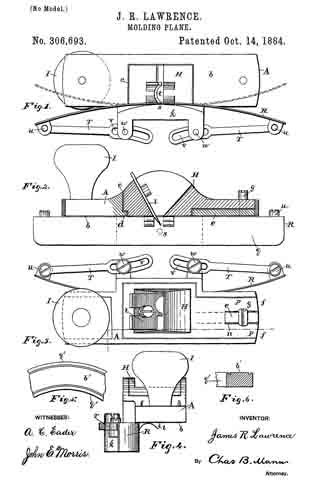
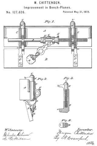
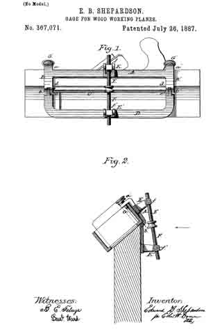
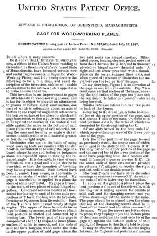
In my drawings, Figure 1 is an elevation of the gage as seen from the outside. Fig. 2 is a transverse vertical section of the same, showing the application of the gage to a plane and the relation of the latter to a piece of material being beveled.

Similar reference-letters indicate like parts in both of the figures.

Referring to the drawings, A is the horizontal bar of the upper portion of the gage, and B B’ are the T ends ofthe same, provided with bent portions a a’ b b’, the latter of which are connected by the strengthening-bar C.

d d’ are slots formed in the bent ends b b’, which receive the tongues e e’ of the lower portion of the gage.

D is the lower portion of the gage, formed as previously stated, the tongue ends of which are hinged in the slots of the T-pieces B B’. The long bar of the upper portion of the gage and the curved bar of the lower portion of the same have projecting from their centers outward bifurcated pieces or clevises E E’. In the outer ends of these clevises are pivoted swivel-nuts f f’, adapted to receive the right and left ends of the double screw F.

The bent T ends a a’ have screw-threaded openings to receive the screws G G’, the clamping ends of which latter may be threadless.

In applying this gage to a plane I place the bent portions a a’ on one of the side walls, with the long bar A resting against the outside of said wall and the clamping-screws — not yet driven down — against the inside of the same. The gage should be so placed upon the plane that one of the clamping-screws shall be in front of the handle and the other rearward of the same. When the screws are driven down to place, they impinge upon the bottom plate of the plane and draw the bent ends b b’ of the gage up against the bottom surface of said plane, and the gage is thus firmly held to place.

It may be observed that the interior angles between the T-pieces and portions a a’ are less than right angles, so that the screws when driven home find their places in the angle of the plane formed by the inner surface of the bottom and the inner surface of the said side wall. The gage being thus firmly secured to the plane, when the angle of the bevel to be made is determined the lower or U -shaped bar of the gage is moved about its axis by the right-and-left screw G G’ until the proper angle is formed. The gage is now applied with the plane to the piece of material to be planed in such a manner that the inner surface of the U-shaped bar rests against one side of said material and the bottom surface of the plane upon the edge of the same to be beveled.

The operator has only to keep the gage upon the guiding-surface of the material as he operates the plane to insure accurate work.

Having thus described my invention, whatl claim as new, and desire to secure by Letters Patent, is —

In a gage for use with wood-working planes, the combination, with the upper portion provided with clamping-screws, a swivel-nut, and jaws or bearings for the same, of the lower portion of said gage hinged to the said upper portion, provided with a swivel-nut and jaws or bearings for the same, and the right-and-left screw engaging said swivel-nuts to adjust the two portions, the one with reference to the other, as and for the purpose set forth.

In testimony whereof I affix my signature in presence of two witnesses.

EDWARD B. SHEPARDSON.

Witnesses:
JAMES S. GRINNELL,
FRANKLIN G. FESSENDEN.

No. 323,595 – Plane-Guide (William Wallace Preston) (1885)

[paiddownloads id=”397″]323595


UNITED STATES PATENT OFFICE.

_________________

WILLIAM WALLACE PRESTON , OF COLDWATER, ASSIGNOR TO HIMSELF
AND EDWARD FLOYD PRESTON, OF BISMARCK, MICHIGAN.

PLANE-GUIDE.

_________________

SPECIFICATION forming part of Letters Patent No. 323,595, dated August 4, 1885.
Application filed January 3, 1885. (No model.)

_________________

To all whom it may concern:

Be it known that I, WILLIAM WALLACE PRESTON, of Coldwater, in the county of Branch, and State of Michigan, have invented a new and Improved Plane-Guide, of which the following is a full, clear, and exact description.

The object of my invention is to provide a simple, inexpensive guide or device of improved construction, for attachment to planes, to enable the edges of lumber to be squared or to be beveled at any desired angle either way by the planes, with accuracy and without the aid of a try-square or bevel, and with economy of time and labor.

The invention consists in particular constructions and combinations of parts of the plane-guide and its attachments to the plane, all as hereinafter fully described and claimed.

Reference is to be had to the accompanying drawings, forming part of this specification, in which similar letters of reference indicate corresponding parts in all the figures.

Figure 1 is a side elevation showing my improved plane-guide attached to a plane, as in use in squaring the edge of a board. Fig. 2 is a rear end sectional view of the same. Fig. 3 shows in end view the plane and its guide adjusted to bevel the edge of a board downward toward its finished face. Fig. 4 is an end view with the plane and its guide adjusted to utilize the outer part of the sharp edge of the plane-iron; and Fig. 5 is an end view illustrating the adjustment of the plane and its guide for beveling the edges of boards downward and backward from their finished faces.

The plane-guide in its preferred form consists, mainly, of three meta! parts: the fence A, or guide proper, the plate B, which is to be fixed to the side of the plane-stock, and the part C, which connects the parts A B by the aid of thumb-screws in the various adjustments of the plane-guide, as hereinafter more fully explained.

The fence A consists of a plate, A’, made either solid throughout or cut away at various places to decrease its weight, and having a strong flange, D, projecting at a right angle and in vertical plane from its back or outer face, and preferably from about the center of the plate A’ (See Fig. I.) I prefer to make the plate B with flanges b b at opposite edges, and to form a boss, b’, at the center of its face, to give sufficient body of metal to firrnly hold a thumb-screw, E, which is threaded into the boss. I attach the plate B by screws f, or otherwise, and it may be permanently, to the side of the stock F of the plane, and preferably near where the plane-iron or cutter G passes through the working-face H of the plane, and so that the flanges b b range up and down the side of the plane. The connecting-piece C is made with an upper portion, I, fitted to slide on the plate B between its flanges b b, and having a slot, i, through which the screw E passes, the flange or shoulder e of the screw being wider than the slot, so it may bind the part I to the plate B at any desired adjustment. The lower part, J, of the connection C is in the form of a flange which projects to one side or face of the upper part I, and in a plane at a right angle with said part, I, and so part J may lie face to face with the flange D of the fence A and be fastened to it by the thumb-screws K L, the screw K serving, when loosened, as a pivot on which to swing the parts A C to their various angles of adjustment, and the screw L, which passes through a curved slot, M, of plate D, serving, with the tightened screw K, to bind the parts C A firrnly together when set. The screws K L enter threaded holes in the lower part or flange, J, of the connection C. I cut away the upper edge of the fence-plate A’, as at a, and for a depth a little greater than the maxirnum projection of the plane-iron G from the plane-face H, so that said face always may lie closely on the upper edge of the fence-plate, and the pivot-screw K is located in such relation to the parts A C of the plane-guide that the corner of the plane-iron nest the guide always will project inward beyond the contacting faces of the fence A and the board O to be jointed, as seen best in Figs. 2 and 3. The adjustment and operation of my improvement are as follows: In jointing the edges of boards O squarely with their finished face o, against which the fence-plate A is held and moves as the plane is operated, or in jointing at a slight back bevel or undercut suitable for the edges of base-boards, door-jambs, and the like, or in jointing at any bevel from forty-five degrees (more or less) downward toward the face o of the work, the part C will be adjusted with its lower part or flange, J, outward, so that the screw K may be entered into the threaded hole 1 of said flange, as shown in Figs. 2 and 3. In square-jointing the boards the fence-plate A’ will be set square with the edge of the plane-iron when the screw E binds the parts C B together, so that the plane-face H rests on the top of the fence-plate A’, as seen in Fig. 2, and the screw L then will be passed through the slot M into the threaded hole 2 of the flange J, and the screws K L then are tightened and the plane is ready for work. To bevel the edge of the board O under slightly toward the back, the screws E K L will be loosened and the plane will be swung over to the right hand on pivot K, or the fence A swung under the plane to the desired angle, and the screws K L will be tightened. The loose screw E, which had allowed the plate B to lift or draw upward on the part I of connection C, will then be tightened, when the plane-face H rests on the upper edge of the fence-plate A’, and the plane is ready for work. To bevel the edge of the board O downward toward its face o, the screws K L will be loosened, and the connection C and the plane will be swung downward to the left hand, the screw L then moving through the slot M, and when the plane-face H stands at the desired angle with the working-face of the fence-plate A’, the screws K L will be tightened; but this adjustment throws the plane-face H away from the fence-plate A’, and to bring them in contact the screw E will be loosened, so that the part I of connection C may be slid upward, or the plane and its plate B be slid downward until the plane-face H rests against the top of the fence-plate A’, the flange D being out away at d to allow this adjustment, and the screw E then will be tightened and the plane is ready for work, as seen in Fig. 3, which shows the tool set to joint the edge of the board at an angle of forty-five degrees; but the adjustments to work at angles greater or less than that shown may readily be made as the work to be done shall require. In squaring or slightly back-beveling the edges of the boards, with the pivot-pin K entered in the screw-hole 1 of the flange J, as in Fig. 2, the left-hand side or edge portion, g, of the plane-iron G will be used, and to provide for utilizing the right-hand sharp edge portion, g’, of the iron when the portion g becomes dulled by use so as to avoid frequent whetting or sharpening of the iron, and also to provide for jointing the boards at a considerable back bevel, the connection C will be reversed in position, and the pivot-screw K will be entered into the screw-hole 2, and the screw L will be turned into the screw-hole 3 of the flange portion J of connection C, as in Figs. 4 and 5. In squaring the edges with the part g’ of the plane-iron, as in Fig. 4, the screws K L will be tightened when the screw L is at or near the lower part of the slot M of flange D; but in setting the plane over to joint at a back downward bevel at any desired inclination from a square edge to an angle of forty-five degrees or more, the screw L will move upward in the slot M, more or less, as required, and the screw E will be tightened when the face H of the plane rests on the top edge of the fence-piece A’. In Fig. 5 the plane is set to back-bevel the lumber at an angle of forty-five degrees.

It will be seen that in every described adjustment of the plane and guide the plane-face is in contact with the guide fence-piece A’, and that it only is necessary in using the plane to hold the fence-piece flat against the finished face of the lumber to secure accurately squared or beveled edges of the lumber, and without the inconveniences and delays incident to the use of try-squares or bevels, thus enabling the workman to do more accurate work and a largely-increased amount of it in a given time.

If desired, the plate B may be let in flush with the side face of the plane, and when a plane is to be used for squaring or for beveling at one angle only, the plate B may be dispensed with and the upper plate or part, I, of the connection C will then be fastened directly to the side of the plane-stock; but the use of the plate B and screw E is preferred for securing the various adjustments allowed by them with a single plane, as above described.

Any suitable fastenings may be substituted for the thumb-screws K L which will serve their purpose — such as nutted bolts; but the thumb screws are preferred because of their convenience in effecting the adjustments of the plane-guide.

Having thus described my invention, what I claim as new, and desire to secure by Letters Patent, is —

1. A plane-guide comprising a fence, A, formed of a plate, A’, having a flange, D, provided with a curved slot, M, and a set-screw, K, passing through the said flange in the same horizontal plane as the upper end of the slot, a reversible connecting-piece, C, formed with the lower flange, J, and upper plate, I, in planes at right angles to each other, the said flange J having holes 1 and 2 in horizontal alignment, and the set-screw L, whereby the set-screw K may serve as a pivotal point and the set-screw L the adjusting point to allow of adjustments, substantially as set forth.

2. A plane-guide comprising a fence, A, formed of a plate, A’, having a flange, D, provided with a curved slot, M, and a set-screw, K, passing through the said flange in the same horizontal plane as the upper end of the slot, a reversible connecting-piece, C, formed with the lower flange, J, and upper plate, I, in planes at right angles to each other, the said flange J having holes 1 and 2 near its upper edge in the same horizontal plane, and a hole, 3, near its lower edge, and the set-screw L, adapted to engage either one of the said holes, for adjustment when one of the other holes is engaged by the set-screw K as a pivotal point.

3. In a plane-guide, the combination, with the fence A and its flange D at right angles therewith, of the reversible connecting-plate C, having a flange, J , in the plane of flange D, and adljustably pivoted to said flange D, and a binding-screw for locking said parts in their adjusted positions, substantially as set forth.

WILLIAM WALLACE PRESTON.

Witnesses:
WM. H. BENEDICT,
GEO. T. CULVER.

No. 306,693 – Molding-Plane (James R. Lawrence) (1884)

[paiddownloads id=”374″]306693


UNITED STATES PATENT OFFICE.

_________________

JAMES R. LAWRENCE, OF DURHAM, NORTH CAROLINA,
ASSIGNOR OF ONE-HALF TO W. T. BLACKWELL, OF SAME PLACE.

MOLDING-PLANE.

_________________

SPECIFICATION forming part of Letters Patent No. 306,693, dated October 14, 1884.
Application filed August 12, 1884. (No model.)

_________________

To all whom it may concern:

Be it known that I, JAMES R. LAWRENCE, a citizen of the United States, residing at Durham, in the county of Durham and State of North Carolina, have invented certain new and useful Improvements in Molding-Planes, of which the following is a specification.

My invention relates to a molding-plane for curved or circular work; and it consists in certain features hereinafter described and claimed.

In the drawings hereto annexed, Figure 1 is a bottom view of the plane. Fig. 2 is a side view showing a longitudinal section. Fig. 3 is a top view of the plane. Fig. 4 is an end view of the same. Figs. 5 and 6 show a specimen of the curved molding.

The body A is made of cast metal and has a flat sole, b. Its central part comprises a box or recess, c, which has around the inner sides next to the fiat sole an inward-projecting flange, d. At the forward end the body has on top a straight rib, e, extending lengthwise, on each side of which is a straight depression or groove, f. A clamp-screw, g, enters the straight rib and serves to hold the bit-stock H to its place. A knob or other suitable handle, I, is attached to the rear end. Attached to the body at one side is a guide-holder, k, which projects below the sole. The bit-stock H occupies the box or recess c, and the bit l may have its cutter-edge shaped to produce any desired style of molding, a specimen of which is shown in Figs. 5 and 6. The lower edges of the bit-stock rest upon the inward-projecting flange d, and the forward end has at central slit, n, which receives the rib e, and the bifurcations p occupy the straight grooves f each side of the rib. By this construction and arrangement of parts the clamp-screw g may be tightened on top of the bifurcations p, and thereby hold the bit-stock firmly to its seat. The flexible guide R is made, preferably, of a strip of steel thin enough to give it the desired flexible character, adapting it to be bent to suit the curvature of the work. The face q of this guide has position at a right angle to the sole b of the body, and while the latter, with the bit, sets upon the top b of the work to be planed (see Figs. 5 and 6) the guide bears against the curved edge q’. The guide-holder k is permanently attached to the plane-body at one side of the central box or recess. The flexible guide is rigidly secured to the holder k at its center s — that is, at a point midway of the ends of the guide. While the center of the guide is thus held immovable, the extremities may be pressed back or forth in either direction to any desired extent within certain limits, as shown and indicated in Fig. 1. A stay-brace, T, connects each end of the flexible guide with the body of the plane. These serve to hold the guide wherever it may be set — that is, either straight or curved. These stay-braces may have any construction that will enable them to be shifted so as to lengthen or shorten the connection, thereby to alter the adjustment of the flexible guide. In the present instance one end of the stay-braces is jointed at u to the flexible guide, and the other end of each brace has a slot, v. A set-screw, w, passes through the slot and enters the holder. When the set-screws are loosened, the slots allow the connections between the set-screws and the ends of the flexible guide to be lengthened or shortened, thereby causing the guide to be curved as desired. It will be seen that the plane will work in a straight line or in a circle, either inside or outside.

To set the guide for any desired work remove the bit-stock H, loosen the set-screws w, then place the plane-body on the work and press the flexible-guide up to the curve or circle and tighten the set-screws. Now replace the bit-stock and the plane is ready for the work. It will be seen that by this construction the cutting-bit may be set, then by removing the bit-stock and cutter the flexible guide may be readily adjusted to the work.

Having described my invention, I claim and desire to secure by Letters Patent of the United States —

1. A plane having a cast-metal body, A, provided with a central box or recess, c, a bit-stock, H, occupying the recess and having at its end a central slit, n, and bifurcations p, and a clamp-screw, g, in the body, and adapted to be tightened on top of the said bifurcations, as set forth.

2. A molding-plane having in combination a body, A, provided with a central box or recess, and a guide-holder, k, permanently attached at one side of said central box or recess and adapted to be readily removed therefrom, and a flexible adjustable guide secure to said holder, whereby the bit-stock and cutter may be removed to facilitate the adjustment of the flexible guide to the work, as set forth.

In testimony whereof I affix my signature in presence of two witnesses.

J. R. LAWRENCE.

Witnesses:
W. W. ELLINGTON,
S. W. CHAMBERLAIN.

No. 299,843 – Gage (Charles B. Osborn) (1884)

[paiddownloads id=”365″]299843


UNITED STATES PATENT OFFICE.

_________________

CHARLES B. OSBORN, OF CANANDAIGUA, NEW YORK.

GAGE.

_________________

SPECIFICATION forming part of Letters Patent No. 299,843, dated June 3, 1884.
Application filed April 12, 1884. (Model.)

_________________

To all whom it may concern:

Be it known that I, CHARLES B. OSBORN, a citizen of the United States, residing at Canandaigua, in the county of Ontario and State of New York, have invented certain new and useful Improvements in Dado-Guides for Planes; and I do declare the following to be a full, clear, and exact description of the invention, such as will enable others skilled in the art to which it appertains to make and use the same, reference being had to the accompanying drawings, and to letters or figures of reference marked thereon, which form a part of this specifiction.

Figure 1 of the drawings is a face view of my device. Fig. 2 is a vertical sectional view of the same, and Fig. 3 is a transverse section.

This invention has relation to adjustable guides for dado-planes; and it consists in the construction and novel arrangement of the longitudinally-recessed rule, carrying a slotted guide-plate and cam, the slotted extension-bar engaging the guide-plate, a second radially-adjustable clamp-jaw, pivoted to said extension-bar, and devices for holding the extension-bar and clamp-jaws in position after adjustment, substantially as specified.

In the accompanying drawings, the letter A designates the rule or guide-bar, against which the dado-plane is designed to work. In the bottom of this bar is made a longitudinal recess, B, and it is provided with an under face-plate, C, which is longitudinally slotted at D, below the recess of the bar. The lateral margins of the slot D project inwardly beyond the walls of the recess, to forrn slide-guides E for the extension.

F indicates the rear clamp-jaw, which is connected to the rule near its end by a clamp-screw and a pivot, G, which engages a spring, H, in a recess of the rule, giving a little play to the clamp-bar in the direction of the length of said rule. The clamp-screws K pass through a strap, L, and through slots I, which are extended radially in series around the center of the jaw. When the clamp-screws are loosened, the jaw can he turned to the required angle, and then by turning the clamp-screws it can be held at that angle firmly. The biting or holding edge N of the jaw, which is to be pressed against the work, is preferably provided with small teeth a. The slots through which the clamp-screws pass are diametrically opposite to each other, and allow the clamp-jaw to be pressed back a little by the spring. In rear of the clamp-jaw is pivoted a cam, P, which engages the circular back b of the clamp-jaw. When this cam is turned in the proper direction, it will force the jaw forward against the work. The slide bar or extension V is slotted in its sides, or entirely through from side to side, as indicated at R, to engage the guide-edges E of the slotted plate C. This extension is designed to fill the recess of the rule-bar neatly, but so that it will slide easily in its bearing.

Z represents the clamp-jaw, which is pivoted to the inner end of the extension by the clamp-screw S, which engages a nut, T, under the slotted guide-plate C. When the clamp-screw S is turned up hard, it secures the extension-bar in the position to which it has been adjusted with relation to the rule-bar. The clarnp-jaw Z is usually provided with small teeth, and is slotted, as at c, to receive a clamp-screw, J, whereby said jaw is held firnily in position after its angular adjustment.

In operating this device the clamp-screw S is loosened, and the jaws are adjusted to the proper angle for the work, which is received between them. The extension-bar and its jaw are then fastened up to the work, allowing about a quarter of an inch between the edge of the jaw and the work. Then the clamp-screw S is tightened and the cam P is turned forcibly, acting to press the jaws against the work. The rule is now fixed in position to guide the dado.

Having described this invention, what I claim, and desire to secure by Letters Patent, is —

A dado-guide consisting of the longitudinally-recessed rule, carrying a slotted guide-plate, a radially-adjustable clamp-jaw, and cam, the slotted extension-bar engaging the guide-plate, a second radially-adjustable clamp-jaw pivoted to said extension-bar, and devices for holding the extension-bar and clamp-jaws in position after adjustrnent, substantially as specified.

In testimony whereof I affix my signature in presence of two witnesses.

CHARLES B. OSBORN.

Witnesses:
G. GRANGER BENHAM,
BRADLEY WYNKOOP.

No. 295,316 – Rabbet-Plane Attachment (Charles A. Warfield) (1884)

[paiddownloads id=”359″]295316


UNITED STATES PATENT OFFICE.

_________________

CHARLES A. WARFIELD, OF PHILADELPHIA, PENNSYLVANIA.

RABBET-PLANE ATTACHMENT.

_________________

SPECIFICATION forming part of Letters Patent No. 295,316, dated March 18, 1884.
Application filed September 18, 1883. (No model.)

_________________

To all whom it may concern:

Be it known that I, CHARLES A. WARFIELD, a citizen of the United States, residing at the city of Philadelphia, in the county of Philadelphia and State of Pennsylvania, have invented certain new and useful Improvements in Rabbet-Plane Attachments; and I do hereby declare the folioiving to be a full, clear, and exact description of the invention, reference being had to the accompanying drawings, which form part of this specification, in which —

Fignre 1 is a perspective of a plane with my attachment applied thereto. Fig. 2 is an end view, same parts as Fig. 1. Fig. 3 is a perspective of attachment.

My invention has for its object to provide a gage or regulating attachment for a rabbet-plane, whereby the width or depth of at rabbet cut may be controlled without employing a marker or equivalent device. My attachrnent consists of a bar provided with means for attaching it adjustably to the face of a common plane or rabbet-plane, forming a guide or gage therefor, substantially as hereinafter fully set forth.

Referring to the accompanying drawings, A represents a common rabbet-plane, to which my attachment is applied. B represents the attachment, consisting of a bar, preferably of metal, with lugs or flanges b b’ at either end. One of these lugs is serrated, as shown at b2, on its inner side, while the other lug has a screw or equivalent lever, or other securing appliance, by which it is made fast to the plane. When the screw C is turned in, it draws the log b’ against the opposite end of the plane, and so holds the attachment firmly on the latter. One side of the attachment constitutes a straight-edge, b3. The other side may be curved or of any desired configuration.

The attachment is adjusted on the face of the plane, with the straight-edge b3 at the same distance from the edge a of the plane as will equal the depth or width of the rabbet required to be cut. The plane is then ready for use. To cut rabbets of different widths or depths, the attachment must be correspondingly adjusted, such adjustment being very readily effected.

As will be seen, the attachment requires no change to be made in the stock of an ordinary plane, and when removed permits the use of the latter in its ordinary manner.

To prevent the bit d of the plane from coming in contact with the attachment, the latter should have a transverse groove, as shown at b5.

I am aware that it is not new, broadly, to provide a plane with an adjustable guide or gage for the purpose of cutting shelved or channeled sufaces; but such as I have any knowledge of have required a special adaptation of the plane to the purposes of the guide. I therefore do not broadly claim an adjustable rabbeting attachment, but limit myself to a guide of such a construction that it may be applied to any ordinary plane by simply clamping the attachment in place.

What I claim as my invention is —

The rabbet attachment for planes herein described, consisting of bar B, having its upper or inner surface flat and transversely grooved, and provided with lugs b b’ and a screw, C, or equivalent means for securing said attachment to the plane, substantially as shown and set forth.

In testimony that I claim the foregoing I have hereunto set my hand this 7th day of September, 1883.

CHARLES A. WARFIELD.

Witnesses:
LISLE STOKES,
WILL H. POWELL.

No. 228,766 – Bench-Plane Gage (Cyrus Kinney) (1880)

[paiddownloads id=”308″]228766


UNITED STATES PATENT OFFICE.

_________________

CYRUS KINNEY, OF WINDSOR, ONTARIO, CANADA.

BENCH-PLANE GAGE.

_________________

SPECIFICATION forming part of Letters Patent No. 228,766, dated June 15, 1880.
Application filed April 15, 1880. (No model.)

_________________

To all whom it may concern:

Be it known that I, CYRUS KINNEY, of Windsor, Essex county, Province of Ontario, Canada, have invented an Improvement in Bench-Plane Gages, of which the following is a specification.

My invention relates to that class of gages for bench-planes which is specially adapted to be used when squaring or beveling the material; and the invention consists in the peculiar construction and arrangement of parts, as hereinafter more fully described, and then pointed out in the claims.

Figure 1 is a perspective view of a plane-stock with my improvement attached. Fig 2 is a vertical cross-section, showing my device adjusted to bevel the work, and in dotted lines as set to form a square, and as folded up against the side of the stock.

In the accompanying drawings, which form a part of this specification, A represents a plane-stock, to the left-hand side of which I rigidly secure a plate, B. To this plate B, I pivotally secure the angle-iron C, to the free end of which is rigidly secured the gage-plate D.

A thumb-screw, a, having a flat head, passing through the slot b in the angle-iron is tapped into a nut, c, rigidly secured in the side of the plane-stock, and a similar screw, d, is tapped through the angle-iron, as shown, the inner end of which is designed to impinge against the face of the plane. This arrangement of the adjusting-screws allows of a nicety and firmness of adjustment not usually attainable in devices of this character, without the employment of much more complicated means, because by turning out the thumb-screw a the angle of the plate D may be varied to a nicety, and by screwing in the screw d the plate is fastened in the desired position, without chance of variation, as the edges of the slot b bear on the head of the thumb-screw a and thus lock it fast, so that it will not turn accidentally or without considerable force being applied to it.

A gage constructed substantially as herein described can readily be set at right angles to the face of the plane and used for squaring the work, or it may be adjusted so as to form a bevel, care being taken that the gage-plate be held firmly against a straight side.

When desired, the device may be folded back against the side of the plane, which can then be used for all the general purposes to which a plane is put.

To fold the guide back it is only necessary to turn the screw a so that the flat side of its head will be parallel with the slot b, when the guide can be turned back out of the way, as shown in dotted lines on the upper part of Fig. 2.

What I claim as my invention is —

1. The combination of the plate B, attached to a plane, the angle-plate C D, hinged to the plate B, and having a slot, b, at right angles to the hinge, with the set-screw a passing through said slot and screwing into a nut in the plane, and the locking-screw ol bearing against the plane, substantially as and for the purpose specified.

2. In a gage for planes, the combination, with the plate B, of the hinged angle-plate C D, having a slot, b, at right angles to the hinge, and a flat-headed set-screw, a, whereby said plate D may be adjusted at any desired angle, or the plate folded back, by turning the screw a a quarter-revolution, substantially as described.

CYRUS KINNEY.

Witnesses:
H. S. SPRAGUE,
CHARLES J. HUNT.

No. 201,068 – Improvement In Bench-Planes (Harrison P. Taylor) (1878)

[paiddownloads id=”289″]201068


UNITED STATES PATENT OFFICE.

_________________

HARRISON P. TAYLOR, OF MINERVA, OHIO.

IMPROVEMENT IN BENCH-PLANES.

_________________

Specification forming part of Letters Patent No. 201,068, dated March 5, 1878; application filed September 7, 1877.

_________________

To all whom it may concern:

Be it known that I, HARRISON P. TAYLOR, of Minerva, in the county of Stark and State of Ohio, have invented certain new and useful Improvements in Bench-Planes; and I do hereby declare that the following is a full, clear, and enact description thereof, which will enable others skilled in the art to which it appertains to make and use the same, reference being had to the accompanying drawings, which form a part of this specification, and in which —

Figure 1 is a perspective view of a plane with my improved plane-guide attached to the side. Fig. 2 is a similar view, showing the guide-strip attached to the face of plane. Fig. 3 is a side elevation of the guide detached. Fig. 4. is an edge view of the same, and Fig. 5 is an end view.

Similar letters of reference indicate corresponding parts in all the figures.

My invention relates to guides for edge-planing; and consists in the construction of a reversible guide, which may be used either on the side or on the face of the plane, as circumstances shall render desirable, substantially as I shall now proceed more fully to describe, my present invention being an improvement on the invention for which Letters Patent of the United States No. 165,132 were granted to me on the 29th day of June, 1875.

In the drawings, A represents the plane, which may be of any suitable size and construction. The guide consists of a beveled strip of wood or metal, B, upon the beveled side or face of which is secured a metal plate, G, having turned-over parallel side flanges c c, by which a dovetailed slot or groove, b, is formed. In this groove slides a dovetailed plate, D, carrying a set-screw, d, by means of which it may be adjusted in any given position in relation to plate C. Secured at right angles upon plate C is a segment, E, which has a segmental slot, e, and the front edge of which is marked with a graduated scale. (See Fig. 4.)

F is the key-plate, which has a key-hole-shaped slot or mortise, f and is secured to the end of a slotted arm, G G’, pivoted at g to the point or center of the segment E, arms G G’ corresponding, therefore, to the radius of a circle whose center is at g, so that they will move freely on both sides of the slotted segment E. Through slot e passes a set or clamp screw, h, which unites arms G and G’, and by turning which these may be made to clamp the segment firmly, so as to remain immovably in position.

From the foregoing description, taken in connection with the two sheets of drawings, the manner of using my plane-guide will be readily understood. For ordinary use, it is secured upon the side of the plane, as shown in Fig. 1, so that only the narrow edge a of the guide-strip B shall bear against the face of the plane. To apply it to the plane, the bolt x is loosened a little, the large opening in the key-plate F is slipped over the bolt-head, after which the plate is pushed up against the bolt so as to bring the shank into the lower narrow part of the hole or mortise, when the bolt is again tightened, and the guide is in position ready for use. The angle of strip B is then regulated (according to the angle the edge is to have) by means of the clamp G G’, clamp-screw h, and the slotted and graded segment E, while vertical adjustment — that is, the distance between the bolt x upon which the guide is secured and the upper edge of the guide-strip — may be adjusted by means of the sliding plate D and set-screw d, so that my guide may be used on planes having different heights or distances between their side bolts and faces by a simple and easily effected adjustment of the guide.

If the plane-bit is dull in one place, or at one edge or side, the guide-strip B may be reversed, without detaching the adjusting mechanism from the plane, by simply loosening set-screw d, sliding plate C off of plate D, reversing the strip and plate, and sliding it on again from the opposite (thick) side of the strip, after which it is again secured in place by the set-screw d. When in this position (represented in Fig. 2) the strip will project over the face of the plane a width of about an inch, and covering the dulled part of the bit, so that full use may be had of its remaining exposed edge.

The manner of angular and vertical adjustment is, of course, precisely the same as that already described in explaining the adjustment of the guide when used as represented in Fig. 1.

This guide, consisting as it does, of few parts, is simple and durable in construction, will fit any plane, and can be produced at a small cost. It cannot give or spring while in use, but insures a true edge without any deviation from the proper angle, according to the set or adjustment of the guide at starting,

Having thus described my invention, I claim and desire to secure by Letters Patent of the United States —

l. The beveled guide-strip B, having grooved plate C, in combination with the reversible plate D and vertically-adjustable key-plate F, substantially as and for the purpose herein shown and specified.

2. The combination of the slotted, and vertically-adjustable key-plate F with the graduated segment E, provided with the reversible plate D, substantially as and for the purpose herein shown and described.

3 The combination of the reversible plate D, provided with the slotted and graduated segment E, with the beveled or wedge-shaped guide-strip B, substantially as and for the purpose herein shown and specified.

In testimony that I claim the foregoing as my own I have hereto affixed my signature in presence of two witnesses.

HARRISON P. TAYLOR.

Witnesses:
GEO. KRYDER,
JOHN L. GOWER.

No. 184,241 – Improvement In Plane-Guides (William H. Harris And Milo Harris) (1876)

[paiddownloads id=”271″]184241


UNITED STATES PATENT OFFICE.

_________________

WILLIAM H. HARRIS AND MILO HARRIS, OF JAMESTOWN, N. Y.

IMPROVEMENT IN PLANE-GUIDES.

_________________

Specification forming part of Letters Patent No. 184,241, dated November 14, 1876; application filed July 3, 1876.

_________________

To all whom it may concern:

Be it known that we, WM. H. HARRIS and MILO HARRIS, of Jamestown, in the county of Chautauqua and State of New York, have invented certain new and useful Improvements in Plane Guides; and we do hereby declare that the following is a full, clear, and exact description thereof, which will enable others skilled in the art to which it appertains to make and use the same, reference being had to the accompanying drawings, and to the letters of reference marked thereon, which form a part of this specification.

The object of our invention is to furnish a cheap and simple guide for bench-planes, so as to plane or saw any desired bevel; and the nature of the invention consists in the combination of devices employed, as hereinafter more fully set forth.

Figure 1 is a view of the guide, with a protractor and end plate attached to each end. Fig. 2 is a view of the metal plate attached to the end of a plane. Fig. 3 is a side view of the plane and guide, with end plate and protractor attached. Fig. 4 is a view of our invention as applied to a saw-table.

ln the drawings, A represents a semicircular bevel-protractor, made of suitable metal, and having a long circular slot near its center, through which the bolt or screw D passes to secure it firmly to the end plate B, and also a semicircular stud, x, at its lower edge, that turns in the semicircular indentures c c c, and also a lip turned at right angles with its surface, through which screws pass to securely fasten it to the guide C. B is a metal plate, that is securely fastened to the end of a plane, as shown in Fig. 2, and having screw-holes for this purpose, and holes a a a, with a screw-thread cut in them to receive the bolt D. It has also sernicircular indentures c c c in its lower edge to receive the stud x of the bevel-protractor. One of these plates, with the bevel-protractor, is fastened at each end of the plane, and, having the guide C attached, is shown in Figs. 1 and 2. The object of having so many places for the bolt D is that by so doing we can use any part of the face of the plane, and by changing ends with the guide C it will work on the back part of the plane-face, thus enabling us to bevel either edge of the board. The object of indentures c c c and stud x is to form a center for the bevel-protractor to turn on, in order that the corner of the guide C will always retain its relative position with the face of the plane, and as the bolt-holes a a a are placed at an angle of forty-five degrees with the indentures c c c we do not have to use but three indentures c c c for all the bolt-holes, no matter on which side of the plane-face the gage is used.

The plate B may be made with a long slot through its center, and a movable nut to receive the bolt D, or said plate may be made dovetailing, and inserted in a movable plate on which the bevel-protractor moves across the plane; but we prefer the manner shown in the drawings, as it is cheaper and more secure.

By means of the semicircular stud x in the bevel protractor A, and the indentures c c c in the metal plate B, the guide C can be moved to any part of the face of the plane, and the inner corner of said guideis held in the exact center of the circle described by the bevel-protractor A, and the guide is kept close to the face of the plane at any angle it maybe turned without any further adjustment, and by turning the lip d parallel with the face of the plane a much thinner guide can be used and thinner lumber planed without coming in contact with the work-bench.

We claim —

The combination of the bevel-protractor A, having stud x and lip d, with the end plate B, provided with the semicircular indentations c c c, the screw-bolt D, and the guide C, all constructed to operate as shown and described, and for the purpose specified.

In testimony that we claim the foregoing as our own invention we affix our signatures in presence of two witnesses.

WM. H. HARRIS.
MILO HARRIS.

Witnesses:
J. E. GOULD,
J. E. HARRIS.

No. 182,722 – Improvement In Plane-Guides (Andrew J. Teamer) (1876)

[paiddownloads id=”269″]182722


UNITED STATES PATENT OFFICE.

_________________

ANDREW J. TEAMER, OF EVANSVILLE, INDIANA.

IMPROVEMENT IN PLANE-GUIDES.

_________________

Specification forming part of Letters Patent No. 182,722, dated September 26, 1876; application filed June 12, 1876.

_________________

To all whom it may concern:

Be it known that I, ANDREW J. TEAMER, of Evansville, Indiana, have invented certain Improvements in Plane-Guides, of which the following is a specification:

My invention relates to certain improvements in that class of planes in which an adjustable guide hung to the plane is used for determining the angle of the cut to be made by the plane-bit; and the object of my improvements is to so construct a plane of this class that the guide can be readily adjusted to any desired angle. This object l attain in the manner which I will now proceed to describe, reference being had to the accompanying drawing, in which —

Figure 1 is a side view of my improved plane and guide, and Fig. 2 a transverse vertical section of the same.

A is the plane, and B the guide, the latter being secured near each end by means of set-screws a to plates D, each of which has a projection, b, hinged by a bolt or pin, d, to ears e on a plate, F, the latter being secured by means of set-screws f to the side of the plane.

The set-screws a and f, are adapted to vertical slots g in the plates D and F, and each of these slots terminates at its upper end in an opening, i, larger in diameter than the head of the set-screw.

Each of the bolts d, by which the guide B is hung to the plane, is provided with a nut, m, on tightening which the guide may be secured to any angle in respect to the plane to which it may be adjusted. In order that this angle may be accurately determined, I make the projection b of one of the plates D of the segmental form shown in Fig. 2, and on the periphery of this segment make lettered or numbered graduations, a mark, x, on one of the ears to which the projection is hinged, indicating the angle at which the guide B is set in respect to the plane, and the bevel of the edge of the strip which is being operated upon.

In addition to the angular adjustment of the guide B, the latter may, owing to the slots g in the plate F and plates D, be adjusted vertically in respect to the plane, and, owing to the enlarged openings i at the ends of the slots, the plate F may be readily removed from one plane and attached to another, or the guide B may be removed and replaced by a new one. Instead of using a bolt, d, and nut m for clamping the plates D and F, together, as described, a screw-bolt, adapted to a thread out in one of the ears e, may be used.

It will be seen that these bolts answer the twofold purpose of hinging the two plates together, and of securing them in position after adjustment, thus avoiding the necessity of employing a separate thumb-screw in addition to the hinging-pin, as is usual.

It will be evident also that plates similar to the plates D may be substituted for the plate F, and that a plate, F, may be applied to the guide, but the construction shown is preferred.

I wish it to be understood that I do not desire to claim, broadly, a plane-guide hinged to a plane by means of adjustable plates; but I claim as my invention —

1. The combination of the hinging and clamping bolts d with the plane A and plate F, having ears e e, and with the guide B and plates D, having projection b, all substantially as described.

2. The plates D, having slots g, with enlarged openings i, in combination with the guide B and its set-screw a.

3. The combination of the guide B and the plates D, having a graduated segmental projection, b, with the plane A and the plate F, having ears e e, as and for the purpose set forth.

In testimony whereof I have signed my name to this specification in the presence of two subscribing witnesses.

ANDREW JACKSON TEAMER.

Witnesses:
JOHN BRIGGS,
A. C. ANCONA.

No. 178,256 – Improvement In Carpenters’ Planes (Samuel Williams) (1876)

[paiddownloads id=”263″]178256


UNITED STATES PATENT OFFICE.

_________________

SAMUEL WILLIAMS, OF COLUMBUS, OHIO.

IMPROVEMENT IN CARPENTERS’ PLANES.

_________________

Specification forming part of Letters Patent No. 178,256, dated June 6, 1876; application filed March 15, 1876.

_________________

To all whom it may concern:

Be it known that I, SAMUEL WILLIAMS, of Columbus, in the county of Franklin and State of Ohio, have invented certain new and useful Improvements in Carpenters’ Planes; and I do hereby declare that the following is a full, clear, and exact description thereof, which will enable others skilled in the art to which it appertains to make and use the same, reference being had to the accompanying drawings, and to the letters of reference marked thereon, which form a part of this specification.

In the accompanying drawings, Figure 1 is a side elevation of a plane with my improvement attached thereto. Fig. 2 is a vertical transverse section of the same on the line x x, Fig. 1. Fig. 3 is an end view, showing the motion of the guide in dotted line. Fig. 4 is a full-sized view of the clutch-bolt and thumb-screw. Fig. 5 shows a detached modification.

My invention consists of certain novel combinations and arrangements of devices for a simple and efficient bevel-guide for planes, the details of which will be fully understood by the following description:

ln the accompanying drawings, A is a plane-stock, with a groove, B, out in each side, to receive the adjustable slide C, which is cast in the same piece with the male part F of the hinge. This slide has a rib, c, which fits the groove B of the plane, in order to prevent the slide from swinging, and thus throwing the bevel-guide out of place. The guide D is attached to the hinge-piece E, which is very strong, and has a slot with broad bearing-sun faces, to grasp the male part F of the hinge, and hold the same firmly in place. This hinge has a central pivot, G, and a set-screw, H, which passes through the curved slot I, Fig. 2, in order to adjust the bevel-guide to any desired angle. A clutch-bolt, K, passes through the plane-stock A, as shown in Fig. 4, and has one end provided with the clutch K’, to grasp the slide C, while the other end is provided with a thumb-screw or nut, L, and washer, M, for fastening the guide to the plane.

The hinge may be graduated in an arc, so as to set the guide D at any desired angle, as is well understood.

Instead of the clutch- bolt K, an arched plate, N, with a set-screw, O, may be used; but I prefer the clutch-bolt shown in Fig. 4.

If necessary with long planes, two clutch-bolts and two hinges may be used to hold the guide more securely in place.

This guide is very simple, and yet strong and durable, and it is very convenient of adjustment, and may be easily changed from one side of the plane to the other, and thus enable the workman to plane cross-grained stuff, and also prevent the uneven wear of the bit.

Having thus described my invention, I claim —

The slide C, provided with the rib c, in combination with the bolt K, bevel-guide D, and plane-stock A, substantially as and for the purposes set forth.

In testimony that I claim the foregoing as my own I affix my signature in presence of two witnesses.

SAML. WILLIAMS.

Witnesses:
DANIEL BREED,
S. E. CARPENTER.

No. 167,943 – Improvement In Plane-Guides (Walter S. Shipe) (1875)

[paiddownloads id=”254″]167943


UNITED STATES PATENT OFFICE.

_________________

WALTER S. SHIPE, OF MINERVA, OHIO.

IMPROVEMENT IN PLANE-GUIDES.

_________________

Specification forming part of Letters Patent No. 167,943, dated September 21, 1875; application filed August 14, 1875.

_________________

To all whom it may concern:

Be it known that I, WALTER S. SHIPE, of Minerva, in the county of Stark and State of Ohio, have invented an Improvement in Plane-Guides, of which the following is a specification:

In the accompanying drawing, Figure 1 represents an end view of my improved plane-guide, and Fig. 2 a side view of the same.

Similar letters of reference indicate corresponding parts.

My invention has for its object to so improve the plane-guide for which a patent has been granted to me under date of January 6, 1874, and numbered 146,208, that it will work more steadily and accurately, and be readily set to any desired angle.

The invention consists, mainly, of a recessed handle-extension of the yoke part in connection with a slotted arc-piece of the guide-strip connecting plate, the arc-piece being pivoted to the yoke, and set by a clamp-screw thereto. A wire key with bent end is inserted into a hole of the guide-strip for being readily available for turning the clamping-screw nuts.

In the drawing, A represents a plane, to which the yoke B is attached in the customary manner by a clamping-screw at one end, and flanged side extensions at the opposite end. The yoke B is cast at the end below the flanges with a handle-extension, E, that is centrally recessed tor the slotted arc-piece D, which forms, with its guide-plate D1, the connection with the guide-strip C. The slotted arc D extends at right angles from guide-plate D1, and is inserted and pivoted at its center in the handle-extension E. A set-screw, E’, passes through the perforations of the handle E and the slot of the arc-piece for the purpose adjusting the sliding arc to any required angle. The outer circumference of the arc-piece D is graduated, so that the same may be directly set with the guide-strip C to any required degree of inclination toward the plane. The guide-plate D1 is slotted and adjusted in a recess of the guide-strip C, nearer to, or farther from, the plane by a set-screw, D2. A key, F, of strong wire, with bent end is inserted into a socket-hole of guide-strip C, being slightly curved at its longer part to be retained there in with a certain tension without falling out, the shorter bent end serving as handle to withdraw it from the guide-strip. The wire key F is inserted into perforations of the heads of the set-screws, so that they can be easily loosened or tightened, while the key may be securely put away into the socket-hole of the guide-strip without getting lost. The key is thus always at hand tor use for setting the plane-guide, which is steadily and firmly adjusted in the handle-extension or socket-piece of the yoke.

Having thus described my invention, I claim as new and desire to secure by Letters Patent —

The combination, with a guide-strip, C, of plane-clamping yoke B, having recessed extension E, the pivotted slotted arc-piece D, and the clamp-screw E’, as and for the purpose specified.

WALTER S. SHIPE.

Witnesses:
JOHN BREIDENSTEIN,
A. N. BOORY.

No. 165,132 – Improvement In Guides For Bench-Planes (Harrison P. Taylor) (1875)

[paiddownloads id=”245″]165132


UNITED STATES PATENT OFFICE.

_________________

HARRISON P. TAYLOR, OF MINERVA, OHIO, ASSIGNOR TO HIMSELF AND P.
A. PAINTER, OF SAME PLACE.

IMPROVEMENT IN GUIDES FOR BENCH-PLANES.

_________________

Specification forming part of Letters Patent No. 165,132, dated June 29, 1875; application filed May 28, 1875.

_________________

To all whom it may concern:

Be it known that I, HARRISON P. TAYLOR, of Minerva, in the county of Stark and State of Ohio, have invented an Improvement in Guides for Bench-Planes, of which the following is a specification:

Figure 1 represents a perspective view of my improved plane-guide, as attached to a plane. Fig. 2 is an end view, and Fig. 3 a vertical section, of the same on the line c c, Fig. 2.

Similar letters of reference indicate corresponding parts.

The object of my invention is to provide an improved double adjustable plane-guide that may be readily set to any angle, and to any part on the face of the plane, that the whole width of the bit is used and the true face of the plane preserved.

The invention consists of a rectangular slotted or dovetailed piece that is attached to the side of the plane, and provided with a sliding piece, with guide-arms tor the pivoted, graduated, and slotted piece, which is set by a clamp screw, and attached by a slotted base-plate to the beveled guide-strip.

In the drawing, A represents the rectangular piece, by which the guide is attached to the side of the plane by a set-screw, B, passing through a slot or perforation of the same. The free end of piece A is either provided with a dovetail groove at the under side, or with a plain slot tor the purpose of guiding the sliding rectangular piece C, having dovetail or tongue, into any position, to any point on the face of the plane, or in opposite direction to some distance from the same, as required. The sliding piece C is firmly secured when adjusted by a set-screw, C1. The downward-extending part of slide-piece C forms, by a dividing recess, two guide-arms or standards, C2, between which the quadrantal piece D is pivoted, and by means of slot a and set-screw b set to any angle toward the face ofthe plane, according to the graduation of its circumference. A base-plate, D’, at right angles to the quadrantal part, carries, by slot and clamp-screw, a beveled wooden or iron guide-strip, F, which may be brought up to the edge and face of the plane. One or two guides may be used, according to the length of plane or material. The guide attachment is removed by detaching the fastening-screw of the rectangular piece A from the side of the plane, or by leaving the same on the plane, using it as a handle, and taking off the slide-piece with the rest of the attachment.

The guide may be adjusted to use the plane square or at any bevel, the main advantage being the sliding of the guide-strip under the face of the plane.

Having thus described my invention, I claim as new and desire to secure by Letters Patent —

The combination of plate A, slide C, single set-screw C1, and quadrant D, all constructed and arranged as and for the purpose specified.

HARRISON P. TAYLOR.

Witnesses:
JOHN BREIDENSTEIN,
HERBERT NICKELSON.

No. 146,208 – Improvement In Plane-Guides (Walter S. Shipe) (1874)

No. 146,208 – Improvement In Plane-Guides (Walter S. Shipe) (1874)

[paiddownloads id=”224″]146208


UNITED STATES PATENT OFFICE.

_________________

WALTER S. SHIPE, OF MINERVA, OHIO.

IMPROVEMENT IN PLANE-GUIDES.

_________________

Specification forming part of Letters Patent No. 146,208, dated December 18, 1874; application filed November 15, 1873.

_________________

To all whom it may concern:

Be it known that I, WALTER S. SHIPE, of Minerva, in the county of Stark and State of Ohio, have invented a new and Improved Plane-Guide, of which the following is a specification:

In the accompanying drawing, Figure 1 represents a sectional end view of my improved plane-guide as applied to a plane. Fig. 2 is a side view of the same 5 and Fig. 3, a detail horizontal section of the wide pivot on the line c c, Fig. 1.

Similar letters of reference indicate corresponding parts.

My invention relates to an improvement in plane-guides by which the plane is steadied in squaring or beveling to any desired angle without the use of a try-square or bevel; and consists of a yoke, which is firmly applied to the plane, and provided, at one end, with a pivoted guide-strip, which is adjusted by clamping-screws under any required angle to the plane.

In the drawing, A represents the plane; B, the yoke; and C, the guide-strip. The yoke B is rigidly applied to plane A by means of a clamp-screw, a, at one side, and a flanged extension, b, at the other side. The guide-strip C is applied to a connecting-piece, D, which is pivoted, by its semicircular part d, to the outwardly-projecting end of yoke B, below flanges b. The semicircular part d is beveled along its circumference, divided by degrees, and rigidly set to any angle to the plane by a curved wedge-piece, e, which is tightly secured between part d and the beveled projection g, at the outer end of yoke B, by a set-screw, f The slotted extension-piece D projects at a right angle to the semicircular part d, and slides in a recess, h, of guide-strip C, so that it may be carried up to the base of the plane, to be firmly secured by a fixed set-screw and washer, l.

When the plan is to be used with the guide for squaring, beveling, or jointing boards, veneers, &c., the yoke is placed over the plane, and firmly screwed thereon in such a manner that the center of the semicircular part d is slightly below the base of the plane. The set-screw at the edge of the are is then loosened, which allows the swinging of the guide-strip to any desired angle. If the angle between the guide-strip and base of the plane is oblique, the set-screw in the slotted part of piece D is loosened, to give greater play to the guide. When the guide is in position, the set-screw and wedge at the arc are tightened, and the guide moved up till it touches the base of the plane. The set-screw of the guide is then tightened on the slotted piece, and the plane ready for use, saving time and labor, and allowing of various applications in the trade.

Having thus described my invention, I claim as new and desire to secure by Letters Patent —

1. The plane-guide consisting of yoke B, with clamping- screw a, pivoted connecting-piece D, curved wedge-piece e, and guide-strip C, with fixed setscrew l, arranged and applied substantially as and for the purposes described.

2. The yoke B, having projecting end, forming the seat of the semicircular part d of piece D, and beveled projecting lug g, as set forth.

WALTER S. SHIPE.

Witnesses:
E. W. POORMAN,
GEO. W. PATTON.

No. 153,122 – Improvement In Planes (Leonard Shane) (1874)

[paiddownloads id=”231″]153122


UNITED STATES PATENT OFFICE.

_________________

LEONARD SHANE, OF HAMPTON, IOWA.

IMPROVEMENT IN PLANES.

_________________

Specification forming part of Letters Patent No. 153,122, dated July 14, 1874; application filed June 1, 1874.

_________________

To all whom it may concern:

Be it known that I, LEONARD SHANE, of Hampton, in the county of Franklin and in the State of Iowa, have invented certain new and useful Improvements in Planes; and do hereby declare that the following is full, clear, and exact description thereof, reference being had to the accompanying drawings and to the letters of reference thereon, making a part of this specification.

The nature of my invention consists in the use of a device which is secured to the end of a plane, for the purpose of canting the same, for planing beveled surfaces, as will be set forth.

ln the annexed drawings, Figure 1 is an end view of a plane with device attached, and Fig. 2 is a perspective of same. In the figures, A represents the end of a plane, to which is connected, by means of a set-screw, a slotted bar, B. To one end of this bar B is pivoted a triangular guide-plate, D; it is also connected to the bar B by means of a set-screw, i, which works through a slot, e, in said plate. The angle of the bar D can be changed on the end of the plane by means of the set-screw C, and the angle of the plate D can be changed on the bar B by means of its pivot and set-screw i. It will be seen that, by means of these two changes, the plane can be canted so that it will work upon irregular surfaces.

Having thus fully described my invention, what I claim as new, and desire to secure by Letters Patent, is —

The combination, with a plane, A, of the bar B, having the slot a, and the set-screw C, the triangular bar D, pivoted to the bar B, and having the curved slot e, and the adjusting-screw i, all substantially as and for the purposes set forth.

In testimony that I claim the foregoing, I have hereunto set my hand this 11th day of May, 1874.

LEONARD SHANE.

Witnesses:
J. W. McKENZIE,
G. C. HAYES.

No. 129,508 – Improvement In Planes (Levi A. Alexander) (1872)

[paiddownloads id=”200″]129508


UNITED STATES PATENT OFFICE.

_________________

LEVI A. ALEXANDER, OF PITTSFIELD, MASSACHUSETTS.

IMPROVEMENT IN PLANES.

_________________

Specification forming part of Letters Patent No. 129,508, dated July 16, 1872.

_________________

To all whom it may concern:

Be it known that I, LEVI A. ALEXANDER, of Pittsfield, in the county of Berkshire and State of Massachusetts, have invented an Improvement in Planes, of which the following is a specification, reference being had to the accompanying drawing.

My invention consists in providing an edging-plane with an adjustable hinged guide by which the plane may be regulated so as to cut or plane the edge of the wood at any desired angle.

Figure 1 is a side view of a plane having my guide applied, and Fig. 2 an end view of the same.

A represents the plane, constructed in the ordinary manner, and B a long bar provided with arms at which are screwed to the side of the plane so as to hold the bar in place along its lower edge. In each end of the bar B there is mounted a transverse slide, C, and a thumb-screw, D, for fastening the same; and to the inner ends of these slides is hinged the guide E, consisting simply of a flat plate or bar. The guide, thus arranged, can be turned so as to present its face at any desired angle to that of the plane; and, to provide for holding it in the required position, it is provided with a curved arm, F, passing through a stud, c, on the bar B, and the stud provided with a thumb-screw, G, which may be set up against the curved arm so as to hold it firmly. To facilitate the adjustment of the guide at any particular angle, the curved arm F is provided with graduations properly numbered, so that it is only necessary to turn the guide until the proper graduation on the arm is brought in line with the stud c, and then to turn up the thumb-screw so as to fasten the arm. The guide may also be adjusted laterally on the face of the plane by loosening and moving the slides C.

In using the plane it is applied so that the face of the guide bears flatly against the side or face of the wood, so as to hold the face of the plane at the desired angle to the edge of the wood, as shown in Fig. 2, so that, upon operating the plane. it cuts the edge of the wood down to the exact bevel or inclination desired. The guide may, of course, be adjusted so as to cause the plane to cut the edge at a right angle to the face, instead of beveling.

By the use of the guide the trouble of constantly testing and fitting the edge by a hand-gauge in the usual manner is avoided and a perfectly true and even edge produced. The guide may be readily applied to any ordinary plane, and can be quickly removed when necessary.

Having described myinvention, what I claim is —

A guide for planes consisting of a plate, E, hinged by adjustable arms C to the bar B, the latter being provided with the arms a, with the graduated quadrant F, and the means for securing the same in place, all constructed and arranged to be applied to a plane, substantially as and for the purpose set forth.

LEVI A. ALEXANDER.

Witnesses:
LORENZO H. GAMWELL,
ELISABETH ALEXANDER.

No. 127,026 – Improvement In Bench-Planes (Morgan Chittenden) (1872)

[paiddownloads id=”195″]127026


UNITED STATES PATENT OFFICE.

_________________

MORGAN CHITTENDEN OF DANBUBY IOWA.

IMPROVEMENT IN BENCH-PLANES.

_________________

Specification forming part of Letters Patent No. 127,026, dated May 9, 1872.

_________________

SPECIFICATION.

I, MORGAN CHITTENDEN, of Danbury, in the county of Fairfield and State of Connecticut, have invented certain Improvements in Bench-Planes, of which the following is a specifcation:

The object of this invention is to attach to the stock of a common bench or other plane an adjustable and removable guide or fence that can assume any desired angle with relation to the f’ace of the plane; and it consists in the construction and arrangement of the devices necessary to so attach and adjust the fence or guide, as will hereinafter be fully described.

In the drawing, Figure 1 is a side view of a plane-stock guide, and the devices for clamping it to the stock, and adjusting it to different angles; Fig. 2 is an end view of same; Fig. 3 a side view of the clamp, and Fig. 4 a top sectional view of the same.

A represents the stock of the plane; B, the fence or guide. C is a portion of a clamp, by which the fence B is attached to the plane-stock by means of the strap-plate C’, that is made fast to the guide or fence, and is hinged to clamp-piece G at c”; on the lower end of clamp-piece C’ is a hook-like projection, c”’, that takes hold of the under or face side of the plane-stock, as seen in Figs. 2 and 3. D is a screw-rod, having a screw cut upon it a portion of its length from one end. E is a nut, fast on the screw-rod D, and by which the screw rod is turned. E’ is a swivel, having heads e’ e’ through which rod D freely turns, while on one side the connecting-bar has a holding~screw, e”, that holds the swivel fast upon the screw-rod at any desired point, on the opposite side of the swivel is plate f’. The swivel E’ is held to its place by collar e on one side and nut E on the other. F is a diagonal connecting-bar pivoted at f to plate f’, has a screw-swivel at f”, for the purpose of adjusting the length of the diagonal bar; and at the lower end of the screw-swivel is an eye that goes between ears f3 f3, and to which it is pivoted. G is a pivot-plate, pivoted to the outside of the fence or guide-piece B, and has cast upon it ears f3 f3, between which the swivel end of the diagonal connecting-rod or bar is pivoted, and by which the guide or fence is allowed to assume different positions with relation to the face of the plane. H is the upper part of the clamp, and has a hook. h, projecting from one side, and takes hold of the upper side of the plane-stock. This upper part of the clamp fits and slides into the lower and outer part C, and the two parts are held together only by screw h’ h’ is a screw, going longitudinally through clamp-piece H into clamp-piece C, and by turning up the screw brings the hooks h and c”’ nearer to each other, and consequently clamps the device fast upon the plane-stock. Screw-rod D freely slides and turns in a hole in a projecting rib on clamp part, G, at one ofthe clamps, as seen at c, while the screw part of the rod passes through a screw-nut in the other clamp-piece at c’.

The operation is as follows: After the device is clamped upon the plane-stock by turning screw h’ down hard, and thereby firmly securing the fence or guide to the stock by turning nut E, it will force the screw-rod D longitudinally in one direction or the other, carrying with it the upper end of the diagonal connecting-bar F, but by reason of the guide or fence B not moving longitudinally it is forced to turn on hinges c”, and turn outward, making an obtuse angle to the face of the plane; and by reversing the revolution of the nut E the rod D is forced in the reverse direction, and consequently the guide or fence B is pushed so as to form an acute angle to the face of the plane, thus making the fence conform to any angle desired, when it is held firmly in such angle by screw e”.

By this construction the fence or guide can be attached to and removed from any plane-stock without marring or defacing it, and saving much in the expense of having extra planes with the fence attached, as this can be made to be put upon or attached to any plane.

I claim as my invention —

1. The sliding-rod D, diagonal bar F, plate G, and guide or fence B hinged to clamps C C H H, in combination with the plane-stock A, constructed to operate as shown and described.

2. The combination of the parts C of the clamps, straps C’ hinged thereto, screw-rod D, turning-nut E, swivel E’, bar F and plate G with the fence or guide B, constructed to operate substantially as herein described.

3. Attaching the removable and adjustable fence or guide B to the plane-stock A, by means of the clamps formed of parts C, to which the guide is hinged, and H having hooks c”’ and h, and holding-screw h’, in the manner herein described.

MORGAN CHITTENDEN.

Witnesses:
DAVID B. BOODY,
ALFRED BELL.