No. 469,688 – Attachment For Planes (Addison J. Ferris) (1892)
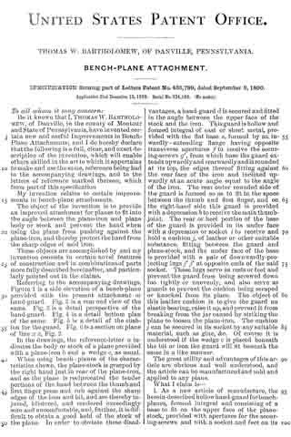
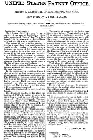
UNITED STATES PATENT OFFICE.
_________________
ADDISON J. FERRIS, OF EAST HAMPTON, MASSACHUSETTS.
ATTACHMENT FOR PLANES.
_________________
SPECIFICATION forming part of Letters Patent No. 469,688, dated March 1, 1892.
Application filed April 13, 1891. Serial No. 388,672. (No model.)
_________________
To all whom it may concern:
Be it known that I, ADDISON J. FERRIS, a citizen of the United States, residing at East Hampton, in the county of Hampshire and State of Massachusetts, have invented new and useful Improvements in Attachments for Planes, of which the following is a specification.
This invention relates or has reference to improvements in planes which are especially designed for finishing rabbeted portions of wood-work and which planes are provided with adjustable gages to accord with the depths of diderent rabbets; and the object of the invention is to improve the device for the purpose indicated, whereby the same may be most readily applied on the stock of almost any ordinary plane, and whereby when so applied it is capable of being most readily or conveniently and minutely adjusted, and when so adjusted it may be maintained against derangement, and also whereby all the parts forming the gage to be applied on the plane may be so united or engaged that even when not applied on the plane they are to all intents and purposes a single fixture, the components of which are not liable to detachment or loss.
The invention consists in the construction and combination of parts, all substantially as will hereinafter more fully appear, and be set forth in the claims.
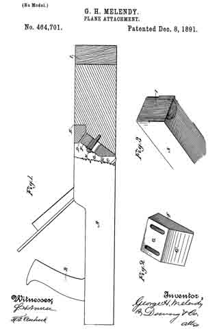
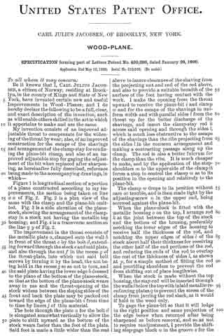
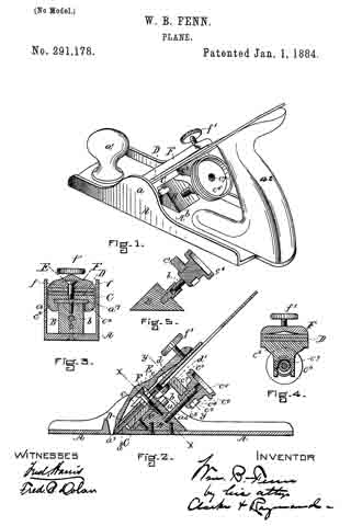
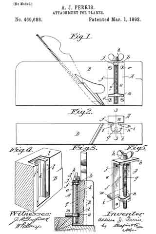
In the accompanying drawings the present improvements are fully illustrated, Figure 1 being a side view of a plane with the gage applied thereon. Fig. 2 is a plan of the bottom of the plane and of the gage, while Fig. 3 is an end view and partial vertical section of the plane and gage, taken on line 3 3, Fig. 2, said parts being shown as in working relation to a rabbeted piece of stock as used fora door or window casing. Fig. 4 is a perspective view of a portion of the plane-stock, showing the same as recessed for the reception of the gage attachment; and Fig. 5 is a perspective view of the gage attachment removed from the plane.
In the drawings, A represents the gage attachment, which, as specially illustrated, consists of a carrier-plate a, provided at its upper end with an angularly-extended portion b, vertically bored, as at d, and said carrier-plate is vertically slotted, as at f which slot is open to the bottom of the plate. The vertical screw g passes freely through the said bore or perforation d and lies alongside of and within the said carrier-plate and is prevented against endwise movement relative to the plate by the fixed thumb piece or head h, above the part b and the collar or nut j below the same.
m represents the gage, which is necked or formed notched intermediately of its opposing edges, as at i, so that the middle of the gage part may be entered in the slot between the side portions of the carrier-plate a, so that a lug or extension at of the gage mlies inside of the plate a and, being bored and tapped, has an engagement with the screw.
It will be seen that, due to the construction of the parts substantially as above set forth, the gage-block has a movable and sliding engagement with relation to the edges of the slot forming the guideway therefor.
The plane-stock B is in its side recessed, as at k, said recess extending from a short distance from the bottom face of the plane-stock to the top thereof, and the said recess at its borders and at the top is provided with the rabbets or rests l l, so that the carrier-plate a may be let within and disposed flush with the sides and top of the stock, nothing projecting outwardly beyond the stock in any direction except the gage proper m and the operating thumb-head. The plate is secured to the plane-stock by the screws o o. On desiring to adjust the gage m so that it will be brought and firmly held on the side of the plane-stock at a greater or less distance from the bottom face of the plane, such may readily and positively be effected by simply turning the screw by its head more or less in the one or the other direction to accord with the depth of the rabbet in the material which is to be finished up.
I therefore claim —
1. The combination, with the plane-stock having the recess in its side, of the carrier-plate a, with the longitudinal slot f and provided with the angularly-extended member b, with the aperture d, the gage m, having the neck guided by the edges of said slotway and provided with the lug n, and the screw g, passed freely through said aperture d and, while freely rotatable, held against endwise movement and having a screw engagement with said lug, all substantially as and for the purposes set forth.
2. An attachment for planes, consisting of the carrier-plate a, having the slot f extending longitudinally from one end thereof and having the angular portion b, with the aperture d, the block having the notched edges i, which have a movable and sliding engagement with the borders of said slot, and said block comprising the gage m and the lug n, which latter has a screw-opening, and the screw g, loosely passed through the aperture h and provided with the thumb-head h and the collar j and having a screw engagement with the said lug n, substantially as deserihed, for the purpose set forth.
ADDISON J. FERRIS.
Witnesses:
WM. S. BELLOWS,
G. M. CHAMBERLAIN.