No. 160,132 – Improvement In Planes (George L. Weaver) (1875)

[paiddownloads id=”238″]160132


UNITED STATES PATENT OFFICE.

_________________

GEORGE L. WEAVER, OF HARTFORD, CONNECTICUT.

IMPROVEMENT IN PLANES.

_________________

Specification forming part of Letters Patent No. 160,132, dated February 23, 1875; application filed May 23, 1874.

_________________

To all whom it may concern:

Be it known that I, GEORGE L. WEAVER, of Hartford, in the county of Hartford and State of Connecticut, have invented a new and valuable Improvement in Planes; and I do hereby declare that the following is a full, clear, and exact description of the construction and operation of the same, reference being had to the annexed drawings making a part of this specification, and to the letters and figures of reference marked thereon.

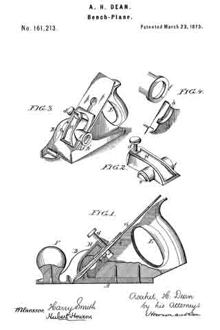
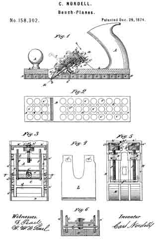
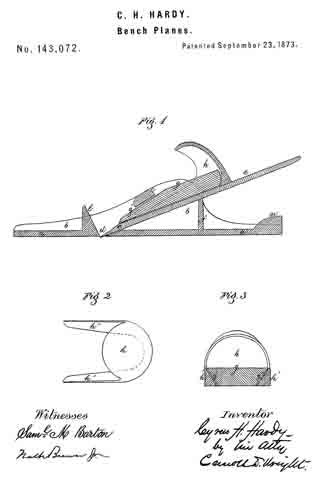
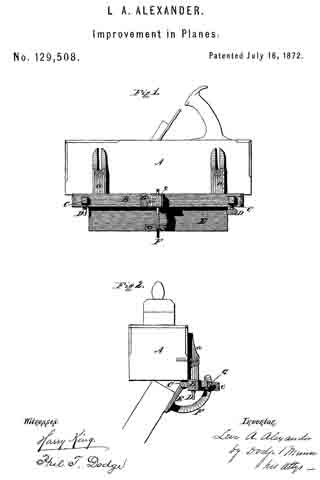
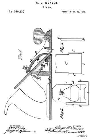
Figure 1 of the drawing is a representation of a sectional view of plane, and Fig. 2 is an end view of the same. Figs. 3 are detail views.

This invention has relation to hand-planes; and it consists in a novel construction of the stock-frame, having stationary inclined beds, and the adjustable wedge having its upper beveled surface parallel with the cutting-iron, as hereinafter more fully described and claimed.

In the annexed drawings, A designates a metal plane-stock, which is constructed with two sides or cheeks, B B, the outer faces of which are perpendicular to the sole of the plane, as shown in Fig. 2. C designates the plane iron or bit, which is supported upon an adjustable bed, D, and a stationary bed, F, and which is rigidly secured thereupon by means of a clamp, G, which is pivoted to cheeks B, at g, and provided with a set-screw, g’. The bed D is wedge-shaped, with an angle coincident to that of the stationary bed F, and parallel with the plane or cutting iron, and is adjustable by means of a screw, E, which adjustment will allow the throat or mouth a to be enlarged or diminished as circumstances require. At the same time the wedge D aftbrds a rigid support for the plane-iron near its lower cutting-edge b. F’ represents a standard, extending upward from the stock, and having its upper end beveled at d, directly opposite the set-screw g’ ofthe clamp, to aftord a bearing-surface for the upper portion of the cutting-iron C. By this construction the cutting-iron C is firmly secured at its lower and upper edges to the inclined beds F d by means of the clamp G and set-screw g’, as shown in Fig. 1.

I am aware that a wedge arranged between the cutting-iron and the bed of the stock, operated by a screw to adjust the cutting-iron, is not new, and therefore I do not claim such invention, broadly; but

What I claim as new is —

The hand-plane herein described, having the stationary inclined beds F d, the adjustable wedge-shaped bed D, having an angle coincident with that of the bed F, and a beveled surface parallel with the cutting-iron C, and affording, with the bed d, a rigid support for the same, and the clamp G, with its set-screw g’, all combined for the purpose set forth.

In testimony that I claim the above I have hereunto subscribed my name in the presence of two witnesses.

GEORGE L. WEAVER.

Witnesses:
FREDERICK EBERLE,
EUGENE D. FISK.

No. 161,213 – Improvement In Bench-Planes (Asahel H. Dean) (1875)

[paiddownloads id=”239″]161213


UNITED STATES PATENT OFFICE.

_________________

ASAHEL H. DEAN, OF PHILADELPHIA, PENNSYLVANIA.

IMPROVEMENT IN BENCH-PLANES.

_________________

Specification forming part of Letters Patent No. 161,213, dated March 23, 1875; application filed January 30, 1875.

_________________

To all whom it may concern:

Be it known that I, ASAHEL H. DEAN, of Philadelphia, Pennsylvania, have invented certain Improvements in Bench-Planes, of which the following is a specification:

The main object of my invention is to so construct a plane having a metal body or frame as to admit of the ready withdrawal, replacing, and adjustment of the plane-bit, and this object I attain in the manner which I will now proceed to describe, reference being had to the accompanying drawings, in which —

Figure 1 is a vertical section of my improved plane; Fig. 2, perspective view of the lever-clamp; Fig. 3, a perspective view of the plane; and Fig. 4, views illustrating part of my invention.

The body of the plane consists of the base A and two side pieces or cheeks, B and B’, the whole being, in the present instance, cast in one piece. The handle E of the plane and the knob F are secured to the base A by screws, in the manner shown in Fig. 1. The plane iron or bit C, which is of the usual construction, and has the usual cap plate h’, bears against a projection, j, of the wooden handle and against a shoulder, i, on the base, the cutting-edge of the bit projecting through a slot in the said base in the ordinary manner, and the bit being confined to its place by a lever-clamp, H, best observed in the perspective views, Figs. 2, 3, and 4. This clamp has on one side a segmental projection adapted to a circular opening in the cheek B, and on the opposite side a ring, f, adapted to a segmental groove, h, formed in the outer face of the cheek B. The projection e and ring f constitute the pivots or fulcrums of the lever-clamp, the upper end of which is caused to bear on the cap-plate by a set-screw, d, in a manner too clearly indicated by the drawing to need description, and to confine the bit to the shoulder on the base and the projection j of the handle.

After loosening the set~screw d, and thereby releasing from its bearings the lever-clamp H, the latter can be removed laterally, its projection e from the cheek B and its ring f from the segmental recess of the cheek B’, thereby permitting the plane-bit to be withdrawn, the clamp being as readily introduced into its place and secured after the adjustment of the plane-bit.

The bearing of the bit on the wooden handle E is an important feature of my invention, for the wood presents a surface to which the bit can be more firmly secured without danger of slipping, when the plane is subjected to accidental jars, than a metal surface.

I claim as my invention —

I. A plane in which the bit is confined to its bearings by a lever-clamp, H, constructed for connection to, and lateral withdrawal from, the frame or body of the plane, substantially in the manner described.

2. The clamp H, its set-screw d, projection e, and ring f, in combination with the cheek B, having an opening adapted to the said projection, and the cheek B, having a segmental recess adapted to the said ring, all substantially as set forth.

3. A plane having a metal body or frame, a wooden handle, and a retaining-screw, or its equivalent, between which and the handle the plane-bit is clamped, all substantially as described.

In testimony whereof I have signed my name to this specification in the presence of two subscribing witnesses.

ASAHEL H. DEAN.

Witnesses:
HUBERT HOWSON,
HARRY SMITH.

No. 161,609 – Improvement In Bench-Planes (Thomas Hagerty) (1875)

[paiddownloads id=”241″]161609


UNITED STATES PATENT OFFICE.

_________________

THOMAS HAGERTY, OF NEW YORK, N. Y., ASSIGNOR TO JOHN ALFRED PICKERSGILL, OF SAME PLACE.

IMPROVEMENT IN BENCH-PLANES.

_________________

Specification forming part of Letters Patent No. 161,609, dated April 6 , 1875; application filed December 2, 1874.

_________________

To all whom it may concern:

Be it known that I, THOMAS HAGERTY, of the city, county, and State of New York, have invented certain Improvements in Bench-Planes; and I declare the following to be a full, clear, and exact description thereof, reference being had to the accompanying drawing, in which the figure is a view of my improvement, the side of the plane-stock being broken away, so as to show the construction of the several parts as they appear in the stock.

The object of my invention is to improve the construction of bench-planes, so that the bit may be conveniently placed out of the way of the hand, held firmly on its bed, and the cutting-edge of the plane-iron be more readily adjusted with reference to the bottom surface of the plane-stock. To this end the invention consists in the combination and arrangement of the devices employed, all as hereinafter described.

In the drawing, A is the plane-stock, made to receive a semicircular bed-block, B. The bed-block rests on projections cast on the bottom of the plane-stock, and is secured to it by screws a a, which pass through oblong holes, which are intended for adjusting the mouth of the stock. C is the plane-iron, bent to conform to the same circle as the bed-block, and is provided with a cap, D, bent to conform to the plane-iron, and secured to it by a clamp-screw, b. The cap iron is slotted crossvvise at its upper end to receive the flange of the adjusting-nut E, and a hole is made through it in front of the clamp-screw b to receive the screw a2, which secures the top clamp F, cap D, and plane-iron C to bed-block B. The clamp F is of a smaller circle than the plane-iron, so that both ends rest on the cap and hold the parts firmly to the bed-block. The adjusting-nut E traverses a male screw, b’, which is set on an incline, so that the flange enters the notch in the cap-iron, and is also provided with a slot in front for applying a screwdriver to operate the bit. The same construction of bit may be applied to scraper-plane by raising the semicircular bed-block to the proper height, and making the bit so as to conform to its circle.

Having thus described my invention, what I claim as new, and desire to secure by Letters Patent, is —

The combination of the plane-stock A with the bed-block B, semicircular bit C, cap D, and adjusting-nut E, provided with screw b, all constructed and operating substantially as herein shown and described.

THOMAS HAGERTY.

Witnesses:
W. G. TUCK,
WM. RUTHERFORD.

No. 165,704 – Improvement In Bench-Planes (Charles Bridges) (1875)

[paiddownloads id=”247″]165704


UNITED STATES PATENT OFFICE.

_________________

CHARLES BRIDGES, OF LOWELL, MASSACHUSETTS.

IMPROVEMENT IN BENCH-PLANES.

_________________

Specification forming part of Letters Patent No. 165,704, dated July 20, 1875; application filed March 20, 1875.

_________________

To all whom it may concern:

Be it known that I, CHARLES BRIDGES, of Lowell, in the county of Middlesex and State of Massachusetts, have invented an Improvement in Bench-Planes, of which the following is a specification:

In the accompanying drawing, Figure 1 represents a top view of my improved plane-stock with handle detached; Fig. 2, a vertical longitudinal section of the plane; Fig. 3, a vertical transverse section of the same on line c c, Fig. 2; Fig. 4, a side view of my extension plane-iron detached; and Fig. 5, a detail side view of the wedge-connection of plane-stock and handle, partly in section, on line x x, Fig. 3.

Similar letters of reference indicate corresponding parts.

The invention will first be fully described, and then pointed out in the claims.

In the drawing, A represents a metallic plane-stock, with throat or slot for the cutter or extension plane-iron B, that is seated on a lateral front ridge, a, and on a central recess, b, of the circular rear partition A’ of the stock. The extension plane-iron B is guided with its narrower rear end or stem in a flanged and slotted shank part, C, being attached thereto by a clamp-screw, d, in such a manner that as the plane-iron is gradually worn out two or more screw-holes, d’, of the front top plate of shank G may be used to secure the iron and extend the same toward the throat. The rear part G’ of shank C is made in the nature of a screw socket or nut for the adjusting screw-bolt D, that is seated by collar e and a thumb-piece, f in the recess b of the rear partition of the stock, producing by the turning of the screw-bolt the forward or backward traveling of the plane-iron. The plane-iron is thus supported in a very simple, substantial, and convenient manner in the plane-stock, without a chance of moving forward or backward, or changing the set of the screw in case the plane is dropped. The plane-iron is instantly placed in the stock and guided exactly into its place, being also readily adjusted to any thickness of shavings by the screw-bolt. The cutter-edge can be squared to the throat or face of the plane by moving the screw slightly to the right or left in the recess of the partition, which is made wide enough for this purpose. The plane-stock A is provided at the sides with projecting wedge-pieces g, and below the same, at the bottom, with inclined ribs g’. The handle part E is made of hollow cast metal to fit the palm of the hand, and bears, by an extension front flange, h, and the plane-iron, and by its sides and rear part, on the sides and rear partition of the plane-stock. To a central socket, i, at the interior part of handle E, is applied, by an adjustable set-screw, i’, a lateral arm-piece, F, that is guided, by recessed side lugs l, along vertical guide-ribs l’ of the handle, according as the arm-piece is adjusted higher or lower in the cavity of the handle. The arms of the arm-piece F extend below the sides of handle E, and are grooved to slide on the wedge-pieces g of the plane-stock, and come, by end lugs m, in contact with the bottom ribs g’ of the same. The arm-piece F is adjusted in such a manner that when the handle is slid forward on the plane-stock, the wedge-pieces and bottom ribs bind rigidly on the ends of the arm-piece, define the position of the handle, and seat the rear part of the handle exactly on the circular rear partition of the stock. The thumb-piece of the lengthening screw-bolt is then turned up, and thereby the handle securely locked to the plane-iron and stock, so that no detaching during use is possible. The plane-iron, being thus entirely within the handle, is not liable to the accidents occurring frequently in metallic planes-namely, the driving forward of the cutter, by a hard blow or fall, into the throat of the stock, on which it acts like a wedge, bursting the throat and spoiling the plane. The plane-iron is, furthermore, entirely out of the way of the hand, and is far more convenient to use, regulate, and handle. The plane forms one compact and solid body without any parts that are likely to be injured, and offers the greatest facility for being handled and adjusted.

The above-described invention has reference more particularly to my Patent No. 157,438, granted December 8, 1874, on which I esteem it to be a decided improvement.

Having thus described my invention, I claim as new and desire to secure by Letters Patent —

1. The combination of plane-iron B, having narrow rear shank, the holder C, having a slot to receive said shank, and the swiveled screw D f, working in a threaded socket of said holder, as and for the purpose described.

2. The combination of stock A, having wedge-pieces g g on the sides, and ribs g’ g’ on the bottom, with hollow handle E, having socket i, the screw i’, and the arm F, having lugs l, as and for the purpose specified.

CHARLES BRIDGES.

Witnesses:
CHAS. F. HOWE,
DEXTER SYMONDS.

No. 165,884 – Improvement In Bench-Planes (Hans Shogren) (1875)

[paiddownloads id=”249″]165884


UNITED STATES PATENT OFFICE.

_________________

HANS SHOGREN, OF PORTLAND, OREGON.

IMPROVEMENT IN BENCH-PLANES.

_________________

Specification forming part of Letters Patent No. 165,884, dated July 20, 1875; application filed March 19, 1875.

_________________

To all whom it may concern:

Be it known that I, HANS SHOGREN, of Portland, Oregon, and in the county of Multnomah of said State, have invented an Improvement in Bench-Planes, of which the following is a specification:

In the drawings, Figure 1 is a longitudinal section through or near the center. Fig. 2 is an inverted plan, looking upward from the bottom. Fig. 3 is a side elevation, partly in section, showing the movable front.

The nature and object of my invention are as follows: In many kinds of work it is necessary to bring the plane-bit O close against a glue-joint or projecting part of a rabbet, or other angular part rising above the surface to be planed, and with common planes this cannot be done, on account of the fore part of the plane in front of the bit, and after planing with them the end can only be finished with a chisel; but by the arrangement herein shown the work may be fully done by the plane itself. To accomplish this the fore part L of the plane R is hung on two screw-centers, G, situated one on either side of the plane opposite the opening for the shavings; and this part L is further provided with a knob, H, in which the nut and screw J are placed, and between H and L a small thumb wrench, I, is placed. The head of the screw J is a sort of eccentric or hook-shape, the sides of the screw-shaft being flattened in such manner that they ht the opening in the center of the wrench I.

Fig. 1 shows the plane when used as a common plane; and Fig. 2 shows the piece L closed in its place in front of the cross-rib K, which is a part of the back portion ofthe plane R. The head of the screw J is hooked. To change this, and put it in the position shown in Fig. 3, the following operation is gone through: First, the knob H, which carries the nut of the screw J, is turned so as to unscrew the nut, and while holding the knob H between the thumb and finger of one hand the other thumb turns the wrench I in such way as to still further unscrew the screw J, and this latter operation turns the screw half round, and disengages it from the cross-rib K. It may now be opened freely, as in the Fig. 3, or thrown entirely back on the top of the plane-iron, and in this position it may be used as now described. By looking at Fig. 2, and at the chip-opening in front of the bit O, an oblique line is seen crossing the under surface of the plane, and at its narrow end to run into the chip-opening. This is the joint between the front part L and the back part of the plane, so that if L were raised up or opened, as in Fig. 3, a portion of the chipway would be entirely open at the front, and half or more would have a narrow bearing in front of the plane-bit. In planing up to a projection this is so arranged that this part prevents the wood from lifting in front of the bit, and having planed to within a quarter of an inch or less of the object the plane is pushed sidewise, and in this way the chip is cut entirely out by the exposed part of the bit, the joint being so arranged that the bit is the foremost object on that side of the plane.

The next feature is the manner of fastening the bit O by means of the forked clamp Q, Fig. 2, screw E, and two pins, F, on theinside of the chip-opening, one on either side, so that the forked clamp Q passes under them somewhat after the manner of the wedge in a wooden plane, and to facilitate keeping Q in its place little hollows are formed on its upper surface, so that they will slightly engage with the pins F, and being so set under the pins F the screw E is tightened, and in this way the bit O is held firmly against its seat in the metal part R. The bit O is like those used in a common wood-plane, having at its back or under side the head of the clamp-screw D.

An arrangement for setting the bit O is as follows: A thumb-lever, A, projecting into the finger-opening in front of the handle N turning on a center, O, Fig. 2, carries a pitman-screw, P, in a joint of its shorter bent end. On the screw P are two nuts, B B’, which turn freely up or down, and are adjustable on the head of the clamp-screw D, and, being in proper adjustment, any movement of A raises the bit up or down. The center G is attached to the bottom of the plane, on the upper side, and beneath the bit O. A forked metal piece, M, Fig. 2, is fastened to the upper part of the handle N by a screw, and the corners or ends of the same to the metal part of the plane near the upper bearings for the bit O, and between these two bearings a vertical web (a bent part of this same piece M) extends, through which a hole is made forming the upper support for the screw P, and all together forming a firm support for the handle N. The whole plane is made of iron or other metal, except the handle N and knob H, which are of wood. The joint between the front and back part is neatly fitted, and the bottom is planed up neat and straight.

I claim —

A bench-plane, provided with the adjustable hinged part L, substantially as and for the purpose specified.

HANS SHOGREN.

Witnesses:
H. M. HUDSON,
CHAS. B. TALBOT.

No. 148,090 – Improvement In Bench-Planes (Quartus Rice) (1874)

[paiddownloads id=”226″]148090


UNITED STATES PATENT OFFICE.

_________________

QUARTUS RICE, OF WASHINGTON, DISTRICT OF COLUMBIA.

IMPROVEMENT IN BENCH-PLANES.

_________________

Specification forming part of Letters Patent No. 148,090, dated March 3, 1874; application filed August 20, 1873.

_________________

To all whom it may concern:

Be it known that I, QUARTUS RICE, of Washington, District of Columbia, have invented an Improvement in Bench-Planes, of which the following is a specification:

Figure 1 is a vertical longitudinal section of a carpenter’s or wood-worker’s bench-plane. Fig. 2 is a plan view of the same.

The nature of this invention consists, first, in the combination of an oil-vessel with the plane, to be operated automatically by the working of the plane; and, secondly, in a presser and cap in one device, constructed and operated as hereinafter more particularly described.

A is a vessel to hold oil. The oil-vessel A has two covers, represented, respectively, by the letters d and e. d is of rigid material. e is elastic, and capable of vibration. f is an iron strap, to which the handle of the plane is fastened, and which is also made fast to the plane at g, and is so constructed that the end y has a slight vibration by pressure on the handle m. b is a tube, through which oil is poured into the vessel A. It is also connected at c with the cover e, and made to slip freely through the cover d, and connect with the strap f at y, so that the vibration of the strap f is communicated to the cover e, and thus the vessel A is alternately contracted and enlarged, and, as the vessel keeps filled with air, the contraction forces the oil out through the aperture at h to the face of the plane, as desired. a is a stopple for the tube b. O is a presser, to hold the cutting-bit firmly in place, and also serves as a cap for the cutting-bit. P is a thumb-screw, for regulating the distance of the cap from the edge of the cutter, by which the frame F, carrying the presser-cap O, is turned upon its pivots o’ o’ in the sides of the plane, while the cap also moves upon the pivots o” o”, by which it is hung to the frame F, and is adjusted to the cutting-bit, so as to press firmly thereon, while the distance from the cutting-edge is also adjusted.

I am aware that there are pressers similar to this, but am not aware of any which act as cap and presser, and regulated in the manner herein described.

I claim as my invention —

1. An oil-vessel, in combination with carpenter’s or wood-worker’s bench~planes, so constructed, in connection with other parts of the plane, that by working the plane the oil will be forced to the face of the plane, substantially as and by the means described.

2. The presser-cap O, constructed as and for the purposes described.

QUARTUS RICE.

Witnesses:
THOMAS C. CONNOLLY,
CAROLINE A. DOLBEAR.

No. 151,682 – Improvement In Planes (Burkner F. Burlington) (1874)

[paiddownloads id=”230″]151682


UNITED STATES PATENT OFFICE.

_________________

BURKNER F. BURLINGTON , OF WAKEFIELD, MASSACHUSETTS, ASSIGNOR TO HIMSELF AND JOSEPH CARTWRIGHT, OF SAME PLACE.

IMPROVEMENT IN PLANES.

_________________

Specification forming part of Letters Patent No. 151,682, dated June 9, 1874; application filed January 28, 1874.

_________________

To all whom it may concern:

Be it known that I, BURKNER F. BURLINGTON, of Wakeneld, in the county of Middlesex and State of Massachusetts, have invented certain Improvements in Combination Plane, Square, and Marker, for Clapboarding, &c., of which the following is a specication:

Figures 1 and 2 of the accompanying drawings are side views. Fig 3 is a central vertical longitudinal section; and Fig. 4 is a central transverse vertical section of my improved combination block-plane, square and marker.

The object of the present invention is to provide a compound tool for clapboarding, &c., by the use of which the inconvenience and loss of time heretofore occasioned by the employment of separate tools, is obviated. My invention consists in a simple, economical, and effective compound tool, arranged, as will be hereinafter more fully explained, to be conveniently used as a block-plane for finishing, as well as for clapboarding; as a marker for properly lining the work for cutting; and as a square for squaring the ends of clapboards, finishing, &c. Also, in providing a simple and effective method of holding and allowing the ready adjustment of the plane-iron; in an adjustable traveling marker-head or holder, arranged to hold or release and allow an up-and-down movement of a suitable blade or marker; in forming the bottom of the plane so as to guide it on the work; and in providing the tool with adjustable plates, arranged to admit of its adjustment to the finish at an angle properly to receive the clapboard to be marked for squaring; all of which I will now proceed to describe.

In the drawings, A represents the front side, B the back side, and C the bottom, of a metallic plane. The sides A and B extend below the bottom C, and form flanges or rabbets a a’, between which the work is guided when planed, the groove b, formed between the flanges a a’, being about an inch wide, or of sufficient width to admit seven-eighths finish, or may be of different width, if desired, for other work. The bottom C at the rear extends laterally from the side A in a curved or other desired shape, and is formed at the end with a transverse downward-extending flange or lip, D, that serves as a square with the bottom of the plane, which latter is formed with a transverse mouth, e, beveled at the required angle on its rear edge. The side A is curved downward on the front, and rounded on the bottom at the forward end, or may be otherwise shaped as desired, and is curved downward at the rear end, and formed with a curved or other suitably-shaped thumb-piece, E, and on the top at a proper distance from the thumb-piece E is formed with a curved or other suitably-shaped finger-piece, F. The side A is formed on the inside at or near its center with a lateral projecting plate, G, inclined on the top toward the front, and rabbeted to receive one side of a plate, H, formed on or attached to the under side of a plane-iron, I, the other side of the plate being held by a rabbet formed in an inclined top of a movable plate, J, held between side lugs f f, or otherwise supported, on the interior of the side B. The adjustable plate J is formed with a central transverse screw-aperture that receives one end of a transverse screw, K, whose other end turns in an aperture formed through the inclined plate G and side A, and on the outside is provided with a suitable head, L, concaved on its face to serve as a thumb-rest when the tool is used for planing. By merely turning the screw k, the plate J is adjusted nearer to or farther from the plate G, thus holding or releasing the plate H of the plane-iron I, which is placed upon the top of the plates G and J, so that the plate H is received between the rabbets of the said plates which are inclined at the angle required to bring the bottom of the iron I in the mouth e of the plane. The bottom C is formed on its top near the front with a finger-rest, M, which is ridged up, and depressed in an elliptical form on its upper face. The side B is higher than the side A, and straight on the top, with rounded corners, or may be curved or formed as desired, so as to allow the exterior to be formed with a longitudinal central groove or slot, N, beveled on its edges, or otherwise arranged to receive and admit the longitudinal travel of an adjustable marker-holder or head. Near each end of the side B is formed on the exterior a vertical slot or groove beveled on the edges, or otherwise formed, to receive and allow the up or down adjustment of a slotted plate, P P’, held or released by a screw, g, that engages in the side B, and bears on, so as to hold the plate in the desired position. These plates P P’ are (when it is desired to mark a clapboard the required length) extended so that their ends abut against the finish, the lower plate P’ being extended a distance beyond the upper plate P equal to the difference between the upper and lower widths of the clapboard, thus allowing the tool to be held at the proper angle to receive the clapboard for marking and squaring. Any desired marker may be arranged as preferred to be adjusted and travel on the side B, but in the present example I prefer to use either one of those represented in the drawings. The marker, shown in Figs. 1 and 4 of the drawings. consists of a vertical plate, h, beveled on the top and bottom edge, or otherwise formed, to be held by and travel in the slot or groove N. From about the center of the plate hprojects upward and outward an open box or frame, i, over the open sides of which extend vertical plates, curved or otherwise connected at the top, and forming a movable head, k, to which is attached the top end of a stem, s, that extends vertically through the box i, wherein is a spiral spring, p, surrounding the stem s, for the purpose of restoring the blade of the marker to its original position after its function has been performed. The lower portion of the stem s is curved inwardly and extended laterally, or otherwise shaped, and formed at the back with a flat surface, having a vertical slot or groove beveled or otherwise formed on the edges to receive a pointed or other properly formed blade or marker, r, which is held or adjusted by means of a screw, n, operating through the face of the lower portion of the stem against the blade.

When desired to use the marker represented in Figs. 1 and 4, the head k is pressed down so as to extend the blade r below the bottom of the tool, and the marker is, by means of the plate h traveling in the slot or groove N, carried down so as to draw the blade across the face of the clapboard or finish against which the tool is held, thus marking the work in the desired manner, the blade after performing its function returning, by means of the spring p, to its former position above the bottom of the tool, which is thus left unobstructed by it for further use.

Having thus fully described my improvements, what I claim as my invention, and desire to have secured to me by Letters Patent, is —

1. A block-plane having the plate G, in combination with the transverse screw K, movable plate J, and plane-iron having rib or plate, as described.

2. The plane, substantially as described, having the adjustable plates and traveling marker, adjusting set-screw, and finger-rests, as described.

3. A marker having a vertical plate, h, arranged to travel in the side of a plane and connected or formed with an upward and outward projecting box or frame, i, having a movable head, k, connected with a stem, s, extending vertically through the box, and supplied with a spiral spring, p, the lower portion of said stem projecting inwardly, and formed with a flat rear face, vertically slotted or grooved to receive an adjustable blade, substantially as specified, and for the purpose described.

In testimony whereof I have signed my name to this specification in the presence of two subscribing witnesses.

BURKNER F. BURLINGTON.

Witnesses:
CARROLL D. WRIGHT,
SAML. M. BARTON.

No. 153,399 – Improvement In Bench-Planes (George M. Thompson) (1874)

[paiddownloads id=”232″]153399


UNITED STATES PATENT OFFICE.

_________________

GEORGE M. THOMPSON , OF BOSTON, MASSACHUSETTS.

IMPROVEMENT IN BENCH-PLANES.

_________________

Specification forming part of Letters Patent No. 153,399, dated July 21, 1874; application filed June 13, 1874..

_________________

To all whom it may concern:

Be it known that I, GEORGE M. THOMPSON, of Boston, in the county of Suffolk and State of Massachusetts, have invented a new and valuable Improvement in Bench-Planes; and I do hereby declare that the following is a full, clear, and exact description of the construction and operation of the same, reference being had to the annexed drawings making a part of this specification, and to the letters and figures of reference marked thereon.

Figure 1 of the drawing is a representation of a longitudinal vertical section of my plane. Fig. 2 is a top plan view, and Fig. 3 is a bottom plan view. Fig. 4 is a transverse section, and Figs. 5, 6, and 7 are detail views. Fig. 8 is an under-side view of the chip E.

This invention has relation to that class of bench-planes having metallic stocks; and it consists, principally, in a bed-frame and moveable carriage for the plane-iron, which carriage is adjustable by means of a rack and segment lever and a thumb-screw, and affords a broad and firm bearing for the plane-iron. It further consists in combining, with the plane-iron and its adjustable bed, a jointed “chip” or wedge, which is provided with a set-screw, by means of which the upper and lower ends of the said chip can be made to bear with considerable force upon the plane-iron, and rigidly hold it in place. My invention consists, further, in constructing V-shaped lugs on the plane-iron carriage, which lugs are adapted to enter notches made in the edges of the plane-iron, and thereby prevent the same from slipping longitudinally when adjusted on its carriage, as will be hereinafter more fully explaned.

The following is a description of my improvements:

In the annexed drawings, A designates a sole-plate, and B B the side flanges or cheeks thereof, which, with the plate, constitute a metal plane-stock, which is cast entire. C and C’ designate the handles of the stock, which are of the usual well-known form, and are secured on top of the sole-plate in any suitable manner. The bottom and top surfaces of the sole-plate are constructed with numerous grooves, a, arranged alternately in regular rows of short sections, which greatly reduce the frictional surface, while at the same time they lighten the stock very much. The grooves a’ on top of the sole-plate are disposed between the grooves a, and also lighten the stock without materially reducing its strength or stiffness. The said grooves run in a direction with the length of the stock, and they are preferably made quite short, so that they will not interfere with the dressing of the edge of a very narrow piece of stuff. D designates a frame, which is rigidly secured upon the sole-plate A, in rear of the throat, by means of a clamp, c. This frame D is constructed with a bearing, b’, for the lower portion of the plane-iron G, the upper portion of which iron is supported upon an inclined carriage or sliding bed, b. This carriage b is guided in the frame D by means of lips p p and hooking-lugs l l, (shown in Fig. 6,) and it is constructed with V-shaped lugs j j, which enter notches i i made in the edges of the plane-iron G, and thus prevent endwise displacement of the plane-iron on its carriage. On the bottom side of the carriage b a rack, r, is formed, the teeth of which engage with a toothed segment, which is formed on the short arm of a lever, F, which has its fulcrum at f on standard h, rising from the base of the frame D. The longer arm of lever F is forked, and embraces an annular groove in an adjusting-nut, g, which nut is applied on a screw, g’, rising perpendicnlarly from a rear extension of the base of frame D. By adjusting the nut g, the carriage b can be moved up and down in the frame D, and the plane-iron can be nicely adjusted according to the thickness of the shaving required. E designates what is denominated the chip, which is of wedge form, and composed of two pieces hinged together at e’, and provided with a set-screw, e. When the plane-iron G is in place on the carriage b and bearing b’, the chip is inserted between it and four hooked lugs, d d d d, after which the parts are rigidly secured in place by means of the screw e, which bears on the plane-iron, and, by centrally bowing up the joint e’, forces the ends of the chip hard down on the plane-iron, as indicated in Fig. 1.

I am aware that similar devices have heretofore been used, as shown in the patent of Leonard Bailey, dated August 6, 1867, No. 67,398, and therefore I do not make claim to any device therein shown.

What I claim as new, and desire to secure by Letters Patent, is —

1. The frame D, constructed with a bed-piece, b’, and provided with an adjustable carriage, D, for the plane-iron provided with the rack r, and combined with cogged segment-lever F and adjusting-nut g, substantially as and for the purpose described.

2. The jointed chip E, provided with a set-screw, e, combined with the frame-lugs d, and the plane-iron G upon its carriage b, arranged as described.

3. The carriage b, provided with lugs j, combined with al plane-iron having notches i i in the edges to correspond therewith, substantially as in the manner shown and described.

In testimony that I claim the above I have hereunto subscribed my name in the presence of two witnesses.

GEO. M. THOMPSON.

Witnesses:
GEORGE E. UPHAM,
FRANK J. MASI.

No. 157,069 – Improvement In Plane-Handles (Frank Goodnow) (1874)

[paiddownloads id=”233″]157069


UNITED STATES PATENT OFFICE.

_________________

FRANK GOODNOW, OF ALBION, NEW YORK.

IMPROVEMENT IN PLANE-HANDLES.

_________________

Specification forming part of Letters Patent No. 157,069, dated November 24, 1874; application filed October 9, 1874.

_________________

To all whom it may concern:

Be it known that I, FRANK GOODNOW, of Albion, in the county of Orleans and State of New York, have invented certain Improvements in Plane-Handles, of which the following is a specification:

My invention consists in the combination of a plane-handle with devices which render it readily attachable and detachable to the plane, so that one handle may be used on any number of planes.

In the accompanying drawing, which is a perspective view, A is a handle of any ordinary form. B is a strap, which is secured to it by means of screws or otherwise, and is provided with the dowels a and b, and also a support at C, for the slotted cap-plate D. The slotted cap-plate D has its fulcrum at c, and is provided with a cam-shaped projection, d. E is a screw, which passes loosely through the slotted cap-plate D into the strap B. On this screw a short lever, F, is placed, which is provided with a cam, which engage with the cam-shaped projection d on the slotted cap-plate D. Two holes, e e, are made in the end of the plane G, corresponding with the dowels a and b. A screw is placed in the top of the plane at f in such a position as to engage with the slotted cap-plate D, which is slotted to receive it.

The handle, having been previously fitted to the plane, is attached to it by passing the dowels into the holes in the end of the plane, and at the same time passing the slotted end of the slotted cap-plate D under the screw f The lever F is now turned; this depresses the end of the slotted cap-plate D, and consequently raises the slotted end, causing it to bear with sufficient force against the under side of the head of the screw f to hold the handle firmly to the plane.

Having thus described my invention, what I claim as new, and desire to secure by Letters Patent, is —

The combination of the handle A, strap B, provided with the support C and dowels a b, slotted cap-plate D, provided with a cam-shaped projection upon its rear end, cam-lever F, and plane G, provided with holes e e, constructed substantially as shown and described.

FRANK GOODNOW.

Witnesses:
GEO. P. HOPKINS,
JOHN A. STRAIGHT.

No. 157,162 – Improvement In Bench-Planes (James Duncan And William H. Talbot) (1874)

[paiddownloads id=”234″]157162


UNITED STATES PATENT OFFICE.

_________________

JAMES DUNCAN AND WILLIAM H. TALBOT, OF BUCHANAN, MICHIGAN.

IMPROVEMENT IN BENCH-PLANES.

_________________

Specification forming part of Letters Patent No. 157,162, dated November 24, 1874; application filed June 17, 1874.

_________________

To all whom it may concern:

Be it known that we, JAMES DUNCAN and WILLIAM H. TALBOT, of Buchanan, in the county of Berrien and State of Michigan, have invented a new and useful Bench-Plane for Scraping Veneers, of which the following is a specification:

The nature of our invention relates to the combination, with a small metallic plane-stock, of a scraping-bit, and certain devices for securing the said bit at any angle or inclination with the plane-throat; and it consists in the peculiar construction and arrangement of the devices for adjusting and securing the scraping-bit in the plane-stock, as more fully hereinafter set forth.

Figure 1 is a perspective view. Fig. 2 is a longitudinal vertical section through the center of the tool. Fig. 3 is a cross-section at x x, in Fig. 4, which is a perspective view of the plane-stock, the bit, segment, and pressure-plate being removed. Fig. 5 is a perspective view of the segment. Fig. 6 is a similar view of the scraper-bit. Fig. -7 is a similar view of the pressure-plate and screw.

In the drawing, A represents a small metallic plane-stock, having the form of the metallic smoothing-plane in common use, provided with the usual handles, and with a transverse throat, a. To the inner side of each cheek is secured or formed therewith a semi-circular shoulder, b, in the radius of the throat a, from which the circle is struck. In the middle, and behind the throat, a shell-like quadrant, A’, rises from the flat of the plane-stock, having the same radius as the shoulders b. c is a screw-threaded bolt tapped through the cheek of one side of the plane-stock, passing through the quadrant and the other cheek, where it receives on its threaded protruding end a tail-nut, C’, by means of which the cheeks may be slightly sprung toward each other, and thus clamp anything fitted between them. B is a sliding segment lying on the shoulders b b and quadrant A’, to the latter of which it may be secured at any point by a set or clamp screw, c’, passing through a longitudinal slot in the segment, and tapped into the quadrant. The segment is still more firmly secured by clamping its sides between the cheeks of the plane-stock by means of the screw c and nut C’. In the fore end of the segment is a transverse slot, d, from the back of which rises a plate, e, which serves as a rest for the steel scraping-bit C which is inserted in the slot, its lower end projecting through the throat a. In front of the bit a pressure-plate, D, is inserted in the slot. A set-screw, f, is tapped through the top of the plate D bearing against the bit, as does the lower edge of said plate D, forcing the bit against the bearing-plate e, thus securing the scraping-bit to the segment B, the former being adjusted to take more or less cut, like an ordinary plane-iron, while it may be adjusted to a vertical position or to any inclination with relation to the work without altering its set, an essential feature in finishing veneers of different woods and structure of fiber or grain.

What we claim as our invention, and desire to secure by Letters Patent, is —

1. The combination, with the plane-stock A having the throat a, of the shoulders b, quadrant A’, segment B, scraper-bit C, pressure-plate D, and screws c’ f, substantially as and for the purpose set forth.

2. The combination, with the plane-stock A, of the shoulder b, quadrant A’, segment B, bolt c, nut C’, scraping-bit C, pressure-plate D, and screws c’ f, as and for the purpose set forth.

JAMES DUNCAN.
WM. H. TALBOT.

Witnesses:
L. P. FOX,
JAMES K. WOODS.

No. 158,302 – Improvement In Bench-Planes (Carl Nordell) (1874)

[paiddownloads id=”236″]158302


UNITED STATES PATENT OFFICE.

_________________

CARL NORDELL, OF NEW YORK, N. Y.

IMPROVEMENT IN BENCH-PLANES.

_________________

Specification forming part of Letters Patent No. 158,302, dated December 29, 1874; application filed June 18, 1874.

_________________

To all whom it may concern:

Be it known that I, CARL NORDELL, of the city of New York, in the county and State of New York, have invented certain Improvements in Bench-Planes, of which the following is a specification:

The object of my invention is to furnish a hand-plane in which the tooth can be used shorter than in other planes, held in place and adjusted to the proper depth of cut and clearance for the shavings without the use of a double or covering tooth, or of the ordinary wedge, or the necessity of adjustment by hammering, and in which a durable metallic surface may be employed without liability of sticking to the surface of the work in consequence of the adhesion resulting from the well-known affinity between the metal and the rosin of the wood.

To accomplish this the invention consists, first, in a metallic cap, adjustable by means of a screw, or equivalent, to give the desired clearance for the shavings, and tightened against the tooth by means of a cam-lever pivoted to a screw adjusted in a threaded socket, which socket is pivoted on a spring-wire, or equivalent spring, which latter, held in permanent position at its two ends, allows ofa yielding at its middle to any extra or over pressure of the cam on the cap. This cap, with the cam-lever, thus does the purpose of the ordinary double or covering tooth and tightening-wedge. Second, in the combination of stationary springs with movable and adjustable screw-slides operating in the cap, and provided with cleats and stops, in such a manner that, when the cam-lever is thrown forward to loosen, but not remove, the cap, the tooth, which is provided with holes or slots suitable to encompass the said cleats, when the upper end of the tooth reaches the said stops, may be easily inserted between the said springs and the slides, and when pushed up against the said stops will be lodged on the said cleats by the pressure of the said springs, after which the depth of the tooth, or of the cut, is regulated. by operating the slides by means of its screws pivoted in the cap. When the cam is loosened the tooth may be instantly removed, when required, by simply pressing down the rear end of the cap against the ends of the springs placed under the tooth. This pressure raises the forward end of the cap sufficiently to release the tooth from the cleats, and allow it to slide out through the opening in the face of the plane. Third, in providing a combined metallic and wooden face of a plane by perforating or socketing the metallic face-plate, and inserting in the holes or sockets so formed one or more diffferent kinds of hard wood, placed with its grain or fibers at right angles to the face of the plane.

In the accompanying drawing, making a part of this specification, Figure 1 represents a longitudinal vertical section of a metallic hand-plane for planing wood, constructed according to my present invention. Fig. 2 is a face view of the same. Fig. 3 is a cross-section of the same, taken through the line x x of Fig. 1, and seen in direction of the arrow. Fig. 4 is a plan view of the under side of the tooth ofthe plane. Fig. 5 is a plan view of the inside of the cap, with its slides and screws for adjusting the tooth. Fig. 6 is a cross-section of the plane, taken through the line y y of Fig. 3.

Similar letters of reference indicate like parts in the different figures.

A are the wooden handles of the plane. B is the metallic face-plate, provided at each edge with upright flanges a1, between which are inserted and secured as well the handles A as the entire mechanism for operating the tooth. The face B is provided with numerous perforations or sockets, into which are tightly in serted the wooden pieces b’, made of any desired shapes and sizes, in such a manner as to form a perfectly smooth and even surface with the metal. C is a metallic frame for supporting the tooth, cap, springs, and sockets, severally above mentioned, and the screw for regulating the cap to give the desired clearance for the shavings. The frame C is provided on the outside with cleats c1 c2, and is of sufficient width outside of the cleats to snugly fill the space between the flanges a1, and is secured to the metal of the plane by entering the cleats c2 tightly between the two cleats a2 a3, formed on each side of the frame C upon the inner sides of the flanges a1, and is fastened at the bottom to the top of the metallic face-plate B by a pin, c3. The frame G may also be secured in any other suitable manner, the mode being immaterial so long as it be held firmly in its place. D are ribs or upright flanges of the frame C, upon which flanges the tooth rests when in position for work. A part of the lower portion of the frame C is formed into a socket, d1, placed across the face-plate of the plane, through which socket, and through holes in the lower part of the flanges D, is inserted a wire spring, d2, which spring also goes through and serves as pivot for the screw-socket E. This socket E is held in a central position in the frame C by being inserted through an oblong hole, e’, in the frame G, previous to the insertion, through the socket E, of the spring d2 The hole, being oblong, allows of an oscillating motion of the socket E, and thus also of a sliding motion of the cap. F are springs attached, with their lower ends, to the bottom of the frame C, and bearing, with their upper ends, against the under side of the tooth, to force the same, when being inserted, into its proper position against the cap, and retaining it there, even when the cap is partly released for adjustment of the cap or of the tooth. The upper cross-bar of the frame C is provided with a threaded hole for the reception of a thumb-screw, G, on which are formed a thumb-nut or milled wheel, g1, a shank, f1, and a button, g2. H is the cap, curved so as to touch with its forward end the lower or forward end of the tooth, whatever be the adjusted position of the cap. The rear end of the cap is formed into a downward-projecting flange, h1, in which is a slot, h2, fitting, when the cap is placed in position on the shank f1, between the thumb-nut g1 and button g2 of the screw G, the circumference of the thumb-nut g1 projecting far enough below the edge of the flange h1 to allow of turning the screw G, whereby the cap H is slid forward or withdrawn, according to the clearance desired for the shavings. In about the center of the cap H is a cup-shaped slotted socket for the reception of the spherical cam of the cam-lever I. This cam is slotted, and in its slot is pivoted the upper end of a screw, l’, the lower end of which enters the socket E. The cap H is also provided, at its upper or rear end, with slots h3, through which project, sufiiciently far to handle, the thumb-nuts j1 of the screws J. The forward ends of the screws J are pivoted in a rib, j2, forming a part of or attached to the cap H. The rear ends of the screws J are pivoted to the pieces i1, attached to the rear end of the cap H. On these pieces i1 are little projections i2, forming a cavity between them, for the reception of the rear ends of the springs F. K are slides, each threaded to form a nut, for the reception of one of the screws J, by turning which they are operated. Each slide K is provided with a cleat, k1, and a stop, k2. L is the tooth, the center of which is cut out so as to allow of its being slid back and forth without interfering with the screw I’ or socket E. In the rear ends of the tooth L are perforations l’, to receive, when the tooth is inserted, the cleats k1 of the slides K.

When the cam-lever is thrown in the position indicated by the dotted lines in Fig. 1, the springs F will raise the cap H sufliciently to allow (while slightly depressing the rear end of the cap H) of the introduction of the tooth L until it is checked by the stops k2 on the slides K. Allowing the springs F to expand, the tooth will be brought, with its slots l’, onto the cleats k1. By now turning either or both screws J, as the circumstances may require, by the hand-nuts j1, the tooth can be adjusted to the depth required, and its edge parallel to the face of the plane. The cap H is then adjusted by the screw G and hand-nut g1, to give the right clearance fbr the shavings. The cam-lever I is then tightened to depress the cap H, and the plane is ready for work.

Should the screw I’ have been turned down in its socket E too far for suiting a thicker tooth, the spring d2 will make up for the difference by yielding enough to allow of bringing the cam-lever down to the surface of the cap H in tightening the cam.

To remove the tooth it is only necessary to loosen the cam and depress slightly the rear end of the cap H.

Having thus described my invention, I claim as new and desire to secure by Letters Patent —

1. The cam and lever I, screw I’, and socket E, in combination with the spring d2, operating as described, and with the cap H, to hold the tooth firmly in place against the ribs D of
the frame C, substantially as specified.

2. The springs F, operating as described, in combination with the pieces i1 on the curved cap H, and the parts I I’ E, for the insertion and removal of the tooth L, and retaining the same while being adjusted, substantially as and for the purpose specified.

3. The screws J, working in the cap H, and provided with thumb-nuts j1, the slides K, with their cleats k1, and stops k2, in combination with the tooth L, provided with the slots l’, for the purpose of adjusting its position, substantially as and for the purpose specified.

4. The cap H, regulated by the screws G, the tooth L, regulated by the screws J and slides K, the cam and lever I, screw I’, socket E, and springs d2 F F, in combination with the frame C, face B, and handles A of a plane, to operate together in the manner and for the purposes substantially as specified.

5. The face of a plane, constructed by inserting pieces of wood b’ in a metallic face-plate, B, with the fibers at right angles to the face, substantially as and ibr the purpose specified.

The above specification of my invention signed by me this 15th day of June, 1874.

CARL NORDELL.

Witnesses:
D. PEARL,
H. W. E. PEARL.

No. 143,072 – Improvement In Bench-Planes (Cyrus H. Hardy) (1873)

[paiddownloads id=”216″]143072


UNITED STATES PATENT OFFICE.

_________________

CYRUS H. HARDY, OF BOSTON, MASS., ASSIGNOR TO JOHN SULLY, TRUSTEE.

IMPROVEMENT IN BENCH-PLANES.

_________________

Specification forming part of Letters Patent No. 143,072, dated September 23, 1873; application filed May 28, 1873.

_________________

To all whom it may concern:

Be it known that I, CYRUS H. HARDY, of Boston, in the county of Suffolk and State of Massachusetts, have invented certain Improvements in Bench-Planes, of which the following is a specification:

Figure 1 of the accompanying drawing is a central vertical longitudinal section. Fig. 2 is a top view of the shield, and Fig. 3 is a transverse vertical section through a portion of the shield and wedge of my improved plane.

The present invention relates to certain new and useful improvements, applicable, mainly, to metallic bench-planes, and having for their principal objects the providing of a rest and shield for the hand of the operator, to serve as a handle, and to prevent the friction of the hand against the sides or frame of the plane, as well as to allow the blade to be readily inserted in or withdrawn from the plane. My invention consists, mainly, in a plane arranged as will be hereinafter more fully described, with a curved shield or guard formed with forward wedge-like projections, or beveled prongs, inserted between an adjustable wedge or block and the top of the blade, so as to securely hold or be readily withdrawn from the latter and form a protection and rest for the hand.

In the drawings, a represents the bottom of a plane, formed of metal or any other suitable material. Projecting upward on each side of the bottom a are curved sides b, connected near the center at the top by a cross-bar, c. The bottom a is formed with a transverse mouth or slot, d, that receives the front “top-beveled” edge of a blade, e, the bottom of which rests on a transverse vertical standard, f, connecting the sides b, and extending up from the bottom a at a sufficient distance from the rear end of the frame to give a proper angle to the blade e. Extending upward, in front of the mouth d, and across the plane, is a finger-rest, l. Inserted between the cross-bar c and the blade e is a block, g, the forward portion g’ of which is beveled on the top to form a wedge, and whose edges g” are beveled inwardly to receive the forward-projecting beveled ends or prongs Ih’ of a curved shield or guard, h. The projecting ends or prongs h’ are beveled on the inside, and extend forward in a longitudinal tapering shape on the top, with a flat bottom, extending in a semicircular form at the back, where the shield or guard It extends upward, curving horizontally a short distance on the sides, and vertically in a segmental elliptical shape, as shown, or in any other form that may be desired, to form a rest for and a protection to the hand.

The wedge and tapering shape of the prongs h’ allow of their ready insertion between or withdrawal from the wedge-block g and the blade e, so as to securely hold the latter, or to permit of its being easily withdrawn or adjusted to the desired position, the blade e being loosened from its position by striking against a block or lug, m, at the rear of the plane.

Having thus fully described my improvements, what I claim as my invention, and desire to have secured to me by Letters Patent, is —

1. In a bench-plane, a curved shield or guard, lt, having beveled projections or prongs h’, arranged and operating substantially as specified.

2. In a bench-plane, the combination of a curved shield or guard, h, wedge-block g, and blade e, all arranged and operating substantially as described.

In testimony whereof I have signed my name to this specification in the presence of two subscribing witnesses.

CYRUS H. HARDY.

Witnesses:
CARROLL D. WRIGHT,
SAML. M. BARTON.

No. 144,381 – Improvement In Bench-Planes (William H. Brown And David F. Williams) (1873)

[paiddownloads id=”219″]144381


UNITED STATES PATENT OFFICE.

_________________

WILLIAM H. BROWN, OF WORCESTER, MASSACHUSETTS, AND DAVID F.
WILLIAMS, OF WOONSOCKET, ASSIGNORS TO BAILEY TOOL COMPANY, OF WOONSOCKET, RHODE ISLAND.

IMPROVEMENT IN BENCH-PLANES.

_________________

Specification forming part of Letters Patent No. 144,381, dated November 11, 1873; application filed April 12, 1873.

_________________

To all whom it may concern:

Be it known that we, WM. H. BROWN, of Worcester, in the county of Worcester and State of Massachusetts, and DAVID F. WILLIAMS, of Woonsocket, in the county of Providence and in the State of Rhode Island, have invented a new and useful Improvement in Bench-Planes; and we do hereby declare that the following is a full, clear, and exact description thereof, reference being had to the annexed drawings making a part of this specification, in which —

Figure 1 represents our improved bench-plane in perspective, and Fig. 2 a vertical longitudinal section of the same.

Our invention consists in certain hereinafter-described means provided for the purpose of facilitating the adjustment of the cap, and for regulating the pressure upon the cutting-tool.

The general construction of our bench-plane is like that described in Letters Patent No. 105,767, granted Joseph R. Bailey, July 26, 1870, an eccentric or curved bar, A, being used in conjunction with a presser-plate, B, to secure the plane-iron D and intervening cap C in the stock E. The presser-plate in this case is elongated and provided with a head, D, and a set-screw, d, the former of which acts in conjunction with other parts presently to be described, while, by means of the lathe, the pressure of said plate against the cam-rod may be adjusted so as to permit of the use of a thick or thin cap or cutting-iron, as desired. It also has lugs e, which project into grooves f cut in each side of the flanges of the stock, at right angles to the cutting-tool, whereby the slipping or sliding of the plate forward or backward is prevented, while at the same time it is allowed to rise and fall under the action of the set-screw d. The accurate adjustment of the cap with reference to the cutting edge of the chisel and the throat of the stock is obtained by means of a set-screw, F, which is carried in a screw-threaded eye in ear c of the cap, and bears with its point against the head b of the presser-plate. The foot of set-screw F being pointed, as shown, a V-shaped groove is formed in the end of head b, to receive such point, and allow the presser-plate to rise and fall and keep it in its exact position.

In the adjustment of the parts, the cap should be properly arranged by adjusting the set-screw F before the eccentric bar is turned down to force the presser-plate against the cap.

We claim as our invention —

1. In a bench-plane of the character described, an adjusting-screw, F, working in an ear, c, formed on or attached to the cap, combined with the presser-plate B, provided with the grooved head b, substantially as and for the purpose set forth.

2. The eccentric A, presser-plate B with lugs e e, grooves f f, and set-screw d, in combination with the cap or plane-iron.

3. The presser-plate B, with lugs e e, in combination with cap C c, set-screw F, and grooves f f substantially as described.

In testimony that we claim the above-described improvement we have hereunto signed our names this 5th day of April, 1873.

WM. H. BROWN.
DAVID F. WILLIAMS.

Witnesses:
F. T. BLACKMER,
W. W. RICE.

No. 144,823 – Improvement In Metallic Planes (Joseph F. Baldwin) (1873)

[paiddownloads id=”220″]144823


UNITED STATES PATENT OFFICE.

_________________

JOSEPH F. BALDWIN, OF BOSTON, ASSIGNOR TO JOHN SULLY, TRUSTEE, OF DEDHAM, MASSACHUSETTS.

IMPROVEMENT IN METALLIC PLANES.

_________________

Specification forming part of Letters Patent No. 144,823, dated November 25, 1873; application filed June 7, 1873.

_________________

To all whom it may concern:

Be it known that I, JOSEPH F. BALDWIN, of Boston, in the county of Suffolk and State of Massachusetts, have invented certain Improvements in Metallic Planes, of which the following is a specification:

Figure 1 of the accompanying drawings is a central vertical longitudinal section of my improved bench-plane. Fig. 2 is a top view of the plane-wedge.

The present invention relates to certain new and useful improvements in bench-planes, particularly applicable to metallic planes, and having for their principal objects the providing of a simple and convenient means of regulating, so as to vary, the cut of the plan-iron. My improvements consist, mainly, in a metallic or other suitable carriage, arranged and operated, as will be hereinafter more fully described, to travel on an inclined screw-rod, and raise or lower the plane-iron so as to vary its cut, as desired.

In the drawings, a represents the bottom, and b the sides, of the plane. c is the mouth, forward of which is an upright transverse plate or finger -bar, d. The bottom a has formed on, or attached to, the top in the center a boss, e, that tapers upward to receive and hold one end of an inclined rod, s, which extends upward through a transverse vertical plate, f connecting the two sides b at the rear of the center of the plane, and notched on the top at the center to allow of the forward and back inclined travel of a metallic or other suitable carriage, g, formed at the top end with a downward-extending flange, g’, bifurcated at the end to straddle a screw-nut, h, formed with a groove, g”, to receive and hold the flanged end g’, and having female screw-threads that mesh with male screw-threads formed on the upper portion of the inclined rod s, which receives on its smooth or lower portion, so as to allow the travel of a flange, i, that depends from the under side of the lower or forward portion of the carriage, g, which is provided on the top near the lower end with an upward-extending stem, k, that fits into an aperture, l’, formed in the iron, l, which may, if desired, be supplied with one or more supplementary apertures, l”, to allow of the wear of the iron, which may thus be placed either higher or lower on the carriage g. The sides b are formed with, or have attached to them, at a suitable distance above, and at the rear of the mouth, lugs m, between the bottom of which and the top of the iron l is inserted the lower portion of a metallic or other suitable wedge, n, the bottom of which is countersunk, and at the upper portion is made open, as shown in Fig. 2, leaving its sides n” to project rearward and upward to form a curved shield, n’. The top edge of the wedge proper is curved, as shown at o, Fig. 2, and formed in the center with a screw-socket, q, that receives a thumb-screw, p, that is operated against the top of the iron l, so as to raise the upper end of the wedge n, which, acting as a lever, with the lugs m as a fulcrum, causes the bottom of the wedge to bear firmly on the top of the lower end of the iron l, which is thus securely held in position; or, by loosening the screw p the iron l is released, so as to allow of its being raised or lowered to suit the desired cut, or to be withdrawn for sharpening or replacement, &c.

It will readily be seen by the above description, reference being had to the accompanying drawings, that the screw-nut h, turning on the screw-end of the rod s, carries the carriage g, connected with the rod s and nut h by the flanges g’ i, up and down, thus raising or lowering, according to the direction in which the nut is turned, the iron l, which is connected by the stem k with the carriage, by whose operation it is thus readily adjusted to the desired cut.

In a large plane the extended sides n” and the shield portion of the wedge are dispensed with, and the curved top portion of the wedge is extended and formed in the shape shown in Fig. 4, with a central screw-socket, q, for the reception of a screw, p.

Having thus fully described my improvements, what I claim as my invention, and desire to have secured to me by Letters Patent, is —

The carriage g, provided with the flanges g’ i and stem k, in combination with the plane-iron l having orifices l’ l”, the nut h having the groove g”, and the screw-rod s, all arranged and operating substantially as described.

In testimony whereof I have hereunto signed my name to this specification in the presence of two subscribing witnesses.

JOSEPH F. BALDWIN.

Witnesses:
SAML. M. BARTON,
CARROLL D. WRIGHT.

No. 145,106 – Improvement In Bench-Planes (George W. Huber And Aaron E. Flickinger) (1873)

[paiddownloads id=”221″]145106


UNITED STATES PATENT OFFICE.

_________________

GEORGE W. HUBER AND AARON E. FLICKINGER, OF NORWALK, OHIO.

IMPROVEMENT IN BENCH-PLANES.

_________________

Specification forming part of Letters Patent No. 145,106, dated December 2, 1873; application filed October 18, 1873.

_________________

To all whom it may concern:

Be it known that we, GEORGE W. HUBER and AARON E. FLICKINGER, of Norwalk, in the county of Huron and State of Ohio, have invented a new and Improved Plane, of which the following is a specification:

In the accompanying drawing, Figure 1 represents a vertical longitudinal section of our improved plane; and Fig. 2, a vertical transverse section of the same on the line c c, Fig. 1.

Similar letters of reference indicate corresponding parts.

The object of our invention is to construct an improved plane, which is light, handy, and easily adjustable to any thickness of shaving without the use of a hammer. Our invention consists in the firm mounting of the plane-iron between a cap-piece with connecting clamping-bolt and set-screw, and a supporting-shoe, which is pivoted to the sides of the base-piece, and adiusted, together with the plane-iron, by a conical eccentric pivoted to the base.

In the drawing, P represents the base-piece of the plane, provided with front and rear handles H, and made preferably of cast-iron. The shoe B is pivoted at a to the side flanges of base A, and supports on its inclined front part the plane-iron D, while the backward-extending bracket-shaped sides rest with their broader ends on rubber cushions b, by which a certain degree of spring action is imparted to shoe B, so as to offer a yielding support to the plane-iron. The face part of shoe B is provided with a recess, d, and extension-slot e, for giving play to the screw-head d’ of the plane-iron D and clamping-bolt f of the cap-piece A. The plane-iron D has a perforation, f’, for the passage of bolt f. A conical eccentric, C, is pivoted to a lug, g, of base P, under the lower extremity of shoe B, and produced under the same inclination of its sides as the front part of shoe B, so as to raise or lower shoe B, as the eccentric C is turned, by means of its handle C’. The plane-iron is thus raised or lowered with shoe B, and the thickness of the planing regulated thereby. The slot through which the plane-iron projects is widened on lowering the iron, so that the thicker shavings may freely pass through the same; while, in raising the iron, the slot is narrowed in proportion to the thinner shavings, and thus the tearing up of the wood or the veneers prevented, and a neat and smooth surface produced. The cap-piece A is placed on the top of the plane-iron D, its clamp-bolt f passing through the slotted part of the iron and into slot e of shoe B. The sides of bolt f are recessed to correspond exactly to the width of slot e, while its broad head projects over the sides of slots e, and holding thereby the plane-iron and shoe in position. By means of a set-screw, h, at the upper end of cap A, the shoe B may be firmly tightened on the iron D, clamping it rigidly between cap A and shoe B. The plane iron is in this manner easily and firmly set into the plane, and readily adjusted to any degree of planing in a neat and convenient manner, economizing time, and forming a compact and strong implement for the trade.

Having thus described our invention, we claim as new and desire to secure by Letters Patent —

The improved adjustable plane, consisting of base-piece P, pivoted shoe B with rubber cushions b, conical eccentrics C C’, perforated plane-iron D, and clamping cap~piece A, constructed substantially as and for the purpose as described.

GEORGE W. HUBER.
AARON E. FLICKINGER.

Witnesses:
E. R. JACKSON,
T. H. KELLOGG.

No. 129,508 – Improvement In Planes (Levi A. Alexander) (1872)

[paiddownloads id=”200″]129508


UNITED STATES PATENT OFFICE.

_________________

LEVI A. ALEXANDER, OF PITTSFIELD, MASSACHUSETTS.

IMPROVEMENT IN PLANES.

_________________

Specification forming part of Letters Patent No. 129,508, dated July 16, 1872.

_________________

To all whom it may concern:

Be it known that I, LEVI A. ALEXANDER, of Pittsfield, in the county of Berkshire and State of Massachusetts, have invented an Improvement in Planes, of which the following is a specification, reference being had to the accompanying drawing.

My invention consists in providing an edging-plane with an adjustable hinged guide by which the plane may be regulated so as to cut or plane the edge of the wood at any desired angle.

Figure 1 is a side view of a plane having my guide applied, and Fig. 2 an end view of the same.

A represents the plane, constructed in the ordinary manner, and B a long bar provided with arms at which are screwed to the side of the plane so as to hold the bar in place along its lower edge. In each end of the bar B there is mounted a transverse slide, C, and a thumb-screw, D, for fastening the same; and to the inner ends of these slides is hinged the guide E, consisting simply of a flat plate or bar. The guide, thus arranged, can be turned so as to present its face at any desired angle to that of the plane; and, to provide for holding it in the required position, it is provided with a curved arm, F, passing through a stud, c, on the bar B, and the stud provided with a thumb-screw, G, which may be set up against the curved arm so as to hold it firmly. To facilitate the adjustment of the guide at any particular angle, the curved arm F is provided with graduations properly numbered, so that it is only necessary to turn the guide until the proper graduation on the arm is brought in line with the stud c, and then to turn up the thumb-screw so as to fasten the arm. The guide may also be adjusted laterally on the face of the plane by loosening and moving the slides C.

In using the plane it is applied so that the face of the guide bears flatly against the side or face of the wood, so as to hold the face of the plane at the desired angle to the edge of the wood, as shown in Fig. 2, so that, upon operating the plane. it cuts the edge of the wood down to the exact bevel or inclination desired. The guide may, of course, be adjusted so as to cause the plane to cut the edge at a right angle to the face, instead of beveling.

By the use of the guide the trouble of constantly testing and fitting the edge by a hand-gauge in the usual manner is avoided and a perfectly true and even edge produced. The guide may be readily applied to any ordinary plane, and can be quickly removed when necessary.

Having described myinvention, what I claim is —

A guide for planes consisting of a plate, E, hinged by adjustable arms C to the bar B, the latter being provided with the arms a, with the graduated quadrant F, and the means for securing the same in place, all constructed and arranged to be applied to a plane, substantially as and for the purpose set forth.

LEVI A. ALEXANDER.

Witnesses:
LORENZO H. GAMWELL,
ELISABETH ALEXANDER.

No. 129,695 – Improvement In Bench-Planes (Thomas Vaughan) (1872)

[paiddownloads id=”201″]129695


UNITED STATES PATENT OFFICE.

_________________

THOMAS VAUGHAN, OF BOSTON, MASSACHUSETTS.

IMPROVEMENT IN BENCH-PLANES.

_________________

Specification forming part of Letters Patent No. 129,695, dated July 23, 1872.

_________________

Specification describing certain Improvements in Bench-Planes, invented by THOMAS VAUGHAN, of Boston, in the county of Suffolk and State of Massachusetts.

My invention relates to a metallic shoe, into which the wooden body of the plane is fitted and secured by means of cement, said shoe being strengthened by ribs before and behind the cutter, and having grooves or flutings cut in various places upon its inner sides to hold the cement.

In the accompanying drawing, Figure 1 is a plan of the shoe, showing its shape, &c. Fig. 2 is a longitudinal section of the same, the shape and position of the plane being shown by dotted lines.

Similar letters of reference indicate corresponding parts.

a is the bottom of the shoe. a’ a’ are the sides and ends. In is the rib in front of the cutter. c is the rib behind the cutter. d is the opening for the cutter. e e e are flutings or grooves in the sides a’ a’.

This shoe is made of malleable cast-iron, and the body of the plane is cut away so as to fit into the shoe. The plane is secured therein by means of prepared cement, the flutings e e being for the purpose of more thoroughly fastening it, the cement filling into them. The ribs b c are intended to strengthen the shoe, and are very important, as it would without them be very liable to break when meeting with a fall from a considerable height. The casting throughout is of uniform thickness, (probably one~eighth of an inch ,) which gives the plane good proportionate weight. In planes made with my shoe I shall construct the cutter of gaged or uniform thickness throughout, so that the opening d shall retain its size and appearance as the cutter wears off. The cutter will also be secured by a wedge in the ordinary way. My plane (having the shoe) will “clean up” the hardest veneer without requiring a scraper, a few rubs with sand-paper being sufficient for any wood requiring the best French polish even.

A plane made as above-described, and having my shoe, costs about one-half as much as planes now in the market and purporting to do similar work. The wear is, of course, unlimited. The general shape of my shoe may be altered, of course, to fit different planes, such as block-planes; but the other features of the invention will be substantially unaltered.

I do not claim as my invention an iron or entirely metallic plane, but my shoe, in which is set a wooden plane, constructed as above described.

Having thus fully described , my invention, what I claim, and desire to secure by Letters Patent, is —

The combination and arrangement of tl shoe and sides and ends thereof a a’, ribs b c, and flutings e e, substantially as above described, and for the purposes hereinbefore set forth.

THOMAS VAUGHAN.

Witnesses:
HENRY W. WILLIAMS,
E. H. OBER.

No. 133,162 – Improvement In Bench-Planes (Jacob Lehner) (1872)

[paiddownloads id=”204″]133162


UNITED STATES PATENT OFFICE.

_________________

JACOB LEHNER, OF GALENA, ILLINOIS.

IMPROVEMENT IN BENCH-PLANES.

_________________

Specification forming part of Letters Patent No. 133,162, dated November 19, 1872.

_________________

To all whom it may concern:

Be it known that I, JACOB LEHNER, of Galena, in the county of Jo Daviess and State of Illinois, have invented a new and useiul Improvement in Bench-Planes, of which the following is a specification:

My invention consists of a combination of screw-rods, nuts, and an adjusting-bar, with the plane stock and bit, in such manner that the setting of the plane-bit is effected by turning the nuts on the screw-rods, the latter being attached to the plane-stock at each side parallel with the bit. My invention also consists of a combination of a tightening-rod with the wedge and plane-bit for securing and releasing the latter; the said rod passing from the heel of the plane-stock through the plane-bit and its cap, which are slotted at the center for the purpose, into the wedge, in which it screws, and the plane-bit having two other slots, one at each side of the center slot, for the screws, by which the cap is secured to it, to allow the tightening-rod to pass through the center slot.

Figure 1 is a longitudinal sectional elevation through my improved plane on the line x x of Fig. 2, and Fig. 2 is a section on the line y y of Fig. 1.

Similar letters of reference indicate corresponding parts.

A is the plane-bit; B, the cap; C, the wedge; D, the screw-rods; E, the cross-bar; and F, the adjusting-nuts. The said rods are attached to the plane-stock, one at each side of the plane-bit, parallel with it, and extend a little higher than the bit does; the cross-bar fits on the rod above the plane-bit, so as to force it down by the adjusting-nuts F, which screw on the rods above the bar, two being used on each rod to fasten one by the other. G is the tightening-rod for fastening the bit and wedge; it passes from the heel of the stock, where it is provided with a thumb-bit for turning it, through the stock to the throat, and through the plane-bit and cap into the wedge, in which it screws. To allow this rod to pass through the center slot K of the plane-bit, a slot, L, is made on each side of it for the screws, by which the cap B is fastened to the bit.

It will be readily seen that the bit may be set and adjusted more accurately and nicely by this apparatus than by the common way of striking it with a hammer; that it cannot be forced back by the work, even though the wedge may not be as tight as necessary; and that the tightening of the latter can be effected better than by driving it in the common way, and the splitting of the stock common to that way of tightening it is avoided.

I am aware ofthe patent granted to J. K. P. Smith on the 9th of May, 1871, (and beg leave to disclaim the same,) but esteem my mode of combining means for holding and adjusting the bit as much simpler and more reliable than those shown by him.

Having thus described my invention, I claim as new and desire to secure by Letters Patent —

The rods D D, cross-bar E, nuts F, and tightener G, combined with wedge, cap, stock, and bit, as described, for the purpose of adjusting and holding the bit at any desired point in the stock.

JACOB LEHNER.

Witnesses:
JOHN McHUGH,
JOSEPH METZGER.

No. 131,544 – Improvement In Bench-Planes (Cyrus H. Hardy) (1872)

[paiddownloads id=”202″]131544


UNITED STATES PATENT OFFICE.

_________________

CYRUS H. HARDY, OF BOSTON, MASSACHUSETTS, ASSIGNOR TO JOSEPH F.
BALDWIN, MELINA C. PATTON, AND JOHN LULLY, OF SAME PLACE.

IMPROVEMENT IN BENCH-PLANES.

_________________

Specification forming part of Letters Patent No. 131,544, dated September 24, 1872.

_________________

To all whom it may concern:

Be it known that I, CYRUS H. HARDY, of Boston, in the county of Suffolk and State of Massachusetts, have invented certain Improvements in Metallic Planes, of which the following is a specification:

Figure 1 of the drawing is a central longitudinal vertical section, Fig. 2 is a bottom view, and Fig. 3 is a part in detail, of my improved metallic planes.

The object of my invention is to provide means for the ready adjustment of the blade of a plane; and it consists in so forming an adjustable shield, in connection with a wedge-block and sides of the plane-frame, to allow a blade to be readily adjusted in or withdrawn from the frame.

In the drawing, a represents the bottom of a frame of a metallic plane, the weight of which is diminished by the formation of openings or slots b, which may be of any form or size, arranged as may be desired, and either left open or filled with wood or other light material or substance. The bottom a is provided with a suitable mouth, c, and has extending across, transversely, and upward a suitable distance, a finger-bar or rest, d, of any desired form. Toward the rear end of the frame is a vertical transverse bar or standard, e, extending upward to the height required to give the proper angle to a blade, f, the bottom of which rests upon it, and whose edge is formed by an upward bevel, f’. The rear end of the bottom a, is formed with a striking-block, g. Extending up from the bottom a are curved sides h, sloping upward toward the center of the plane, where each is cut away so as to leave on the top a projection, i, curved on the under side to admit the turning of an upward-curved portion or cam, k, formed by the forward part of projecting ends of the bottom of a shield, m, which is curved at the sides, back, and top, as shown in Figs. 1 and 3, and has its bottom cut away, as at n, to fit over the top of the blade f and is formed with a bottom frame or plate, o, provided with bearings o’, in which a bolt, p, having a suitable spring, p’, and thumb piece p” , is made to travel back and forth, in and out of a socket, x, formed in the end of a beveled or wedged block, r, formed to it within the curved front of the frame or plate o and the projecting sides l, to the latter of which it is attached by pivots s, or other suitable means, for allowing the shield on to turn over the top of the block r, the bottom of which rests upon the blade f, which is held by the pressure of the wedge-block r and cam k upon it.

Reference being had to Figs. 1-3 of the drawing, it will be seen that, by unlocking the bolt p from the block r, the shield m is, by the action of the cams k and pivot s or its equivalent, allowed to turn over the top of the block r, which is, by the operation, carried up, and lessens its hold on the blade f, which may then be easily withdrawn or adjusted in the desired manner. When the blade f is inserted in the position required the bolt p is unlocked from the wedge-block r, the shield m is turned by the action of the cam k onto the blade f which is securely held by the wedge-block r and cam k, and forms a guard that serves as a support to the hand, the fingers of which find a hold on the forward rest or bar d. The principal function of the spring-bolt p is to prevent the liability of the tipping of the cam is or the forward projections l of the shield m when power is applied to the upper part of the back of the shield. Instead of the bolt p and spring p’, &c., a spring-clutch, or any other suitable device for holding and relieving the wedge-block r, may be used.

It will readily be seen that by my improvements the blade f is inserted at a low angle, which admits of its being readily withdrawn or adjusted, and permits the shield m, which serves as the handle, to be placed near the mouth and center of the plane, and thus prevents the rising of the forward part of the plane, which is often liable to occur when the handle is formed near the rear end of the plane.

Having thus fully described my improvements, what I claim as my invention, and desire to have secured to me by Letters Patent, is —

1. A metallic plane, having a bottom, a, formed with openings or slots b, finger-bar or rest d, curved sides h, arranged with projections i, and cut away so as to receive and admit the turning of cams k, formed by the projecting ends l of the bottom of a curved shield, m, provided with a bolt, p, and spring p’, or their equivalents, and connected with and operating a wedge-block, r, bearing on a blade, f supported by a standard, e, substantially as specified.

2. The shield m, having the recess n, and provided with the frame o, bearings o’, and cam k, and combined with the bolt and spring p p’, block r, frame a e h, and blade f all arranged and operating as described.

3. The wedge-block r, in combination with the shield m, bolt p, and spring p’, or their equivalents, blade f and sides in of a metallic plane, arranged and operated substantially as described.

In testimony whereof I have signed my name to this specification in the presence of two subscribing witnesses.

CYRUS H. HARDY.

Witnesses :
SAML. M. BARTON,
CARROLL D. WRIGHT.

No. 127,541 – Improvement In Plane-Stocks (Samuel M. Adams) (1872)

[paiddownloads id=”196″]127541


UNITED STATES PATENT OFFICE.

_________________

SAMUEL M. ADAMS, OF FITCHBURG, MASSACHUSETTS.

IMPROVEMENT IN PLANE-STOCKS.

_________________

Specification forming part of Letters Patent No. 127,541, dated June 4, 1872.

_________________

To all whom it may concern:

Be it known that I, SAMUEL M. ADAMS, of Fitchburg, in the county of Worcester and State of Massachusetts, have invented an Improved Plane-Stock; and I do hereby declare that the following, taken in connection with the drawing which accompanies and forms part of this specification, is a description of my invention sufdcient to enable those skilled in the art to practice it.

In making patterns for castings it is often necessary to plane long straight faces, which are curved in cross-section, and as such faces differ so that in different patterns there are hardly two faces alike — for which reason there has to be, in every complete set of pattern-maker’s tools, a great variety of planes with curved-faced stocks and curved-edged bits.

My object has been to produce a plane in which the face of the stock could be adjustably curved, so that, with the same or with different bits, and with the same stock, faces to be planed may be brought to various curves, as desired, by fitting the plane thereto.

My invention consists in a plane-stock formed of sections, each of which has a plain straight face in the direction of the length of the plane, said sections being so connected that they may be relatively adjusted so as to present faces more or less curved in cross-section, the faces of the stock being brought to the form desired preferably by means of a pattern or gauge, and being then fastened; while for a bit or cutting-iron there may be selected a bit with a proper-shaped edge; or for slight medications one bit can be used. My invention consists in a plane or plane-stock the face of which is made up of plates or sections hinged together, and made relatively and independently adjustable, and having provision for fastening them in any position to which they may be brought by adjustment.

The drawing represents a plane-stock embodying my invention.

A shows a plan of it; B, a reverse plan or bottom view. C is a cross-section on the line x x D is a cross-section on the line y y.

a denotes the frame of the stock; b, the handle; c, the bit or iron; all made in the usual manner. To the frame as is fixed a center permanent or relatively immovable rib, d, having a face, e, and to the opposite sides of said rib d are jointed two other ribs, f having cutting-faces g, and to the ribs f two ribs, h, with cutting-faces i, and to the ribs h ribs k with cutting-faces l, there being as many of these ribs and faces as may be desirable.

When the faces are in line they constitute the flat face of an ordinary plane, and from this line or plane they are moved, as occasion may require a curved face to be planed. For this purpose the plates are jointed together by suitable ears and pins, as seen at m, and from each a jointed arm, n, extends, the several arms at either end of the plane passing through a sleeve or opening, in which, by means of a cam-lever, o, or an eccentric, p, they may be clamped together.

By means of a plane thus made a great variety of straight work curved in section may be planed with one tool, which work, without such a tool, would require as many planes as there were variations in surfaces to be planed.

The specific construction shown may, of course, be varied, both as relates to the connection of the sections and as to the means for clamping them in position.

I claim —

A plane-stock made up of sections connected together, substantially as shown and described.

SAMUEL M. ADAMS.

Witnesses:
FRANCIS GOULD,
M. W. FROTHINGHAM.