No. 284,919 – Bench-Plane (William Steers) (1883)
[paiddownloads id=”340″]284919


UNITED STATES PATENT OFFICE.

_________________

WILLIAM STEERS, OF SHERBROOKE, QUEBEC, CANADA.

BENCH-PLANE.

_________________

SPECIFICATION forming part of Letters Patent No. 284,919, dated September 11, 1883.
Application filed January 25, 1883. (No model.)

_________________

To all whom it may concern:

Be it known that I, WILLIAM STEERS, a citizen of Canada, residing at Sherbrooke, in the county of Sherbrooke and Province of Quebec, Canada, have invented certain new and useful Improvements in Adjustable Composite Bench-Planes, of which the following is a specification, reference being had therein to the accompanying drawings.

This invention relates to improvements in bench-planes; and it consists in the devices for adjusting the cap upon the cutting-iron, the movements of the cutting-iron, and the closing of the throat of the plane to suit the different materials to be dressed, and also in the construction of the metallic body or frame of the stock, all of which will be hereinafter more fully described, and set forth in the claims.

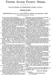
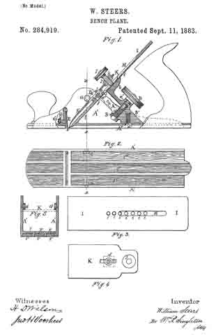
In the drawings forming apart of this specification, Figure 1 is a longitudinal vertical section. Fig. 2 is an under side view of the face of the plane. Fig. 3 is a plan view of the plane-iron on top. Fig. 4 is a plan view of the cap. Fig. 5 is a transverse section on as so of Fig. 1.

A is a lever, pivoted at a, having at its lower end a segment-rack, a’, which meshes with a worm-gear, B, that is supported upon a proper bearing or standard, B’, within the stock of the plane A’, which is in this case secured by a screw, a”, through the bottom plate, A”. This bearing or standard B’ also supports the lever A, and forms a bed at b for the plane-iron I, against which it is pressed by the screw J.

In the plane-iron, on top, is a groove, H, for the foot of the screw J. In the plane-iron I there are holes i i i, into any one of which the small end a”’ of the lever A can be inserted; and below the lever A is one of the holes j, for the insertion of the end of a set-screw, D. Said screw works in a nut, C, below the cap K, and through the orifice d in the cap, for a purpose to be hereinafter explained.

J is a straining or clamp screw, which works in the nut k on the end of the cap-iron K.

G G are studs projecting on the inside of the stock-frame A’, to lock the cap-iron K.

E is a strong spring attached at top to a standard, E’, and its lower end, e, made as wide as the throat of the plane, and forming a casing for the front edge, e, of it.

e’ is an adjusting-screw by which the spring E is made to close the throat to such an adjustment as may be required to suit the character of the material to be dressed.

The adjusting worm-screw B is set in the standard B’ by means of a neck, c, and a retaining-pin, c’, which will allow the screw to be rotated, but prevents its withdrawal.

The bottom plate, A”, is formed with wide grooves F F, in which are inserted hard-wood strips F’ F’, as seen in section, Fig. 5.

The set-screw D is inserted in the hole j, and when the cap K has been properly adjusted to the plane-iron I, the screw D is then tightened, so that the nut C clamps the cap-iron K in its position; and by this device the plane-iron, when removed from the plane to be sharpened, will come to the same position each time, after being sharpened, without any further adjustment, as screw D will be dropped into the same hole each time.

The series of holes i i, &c. , in the plane-iron I is for the purpose of being used successively as the iron is ground away in sharpening, and they are at such a distance apart as to be accommodated to the other devices in connection therewith.

I claim —

1. In planes, the cap-iron K, provided with a slot, a set-screw having a free end passing through said slot, which enters the plane-iron, as shown, and a clamping-nut for fastening the screw at any point in the slot, substantially as and for the purpose described.

2. The cap-iron K, having a clamping-nut and screw, constructed as described, in combination with the plane-iron having a series of holes, andthe lever A, which enters one of said holes, substantially as described.

3. The combination of the spring-plate E, located in the throat of a plane, with the standard E’ and the adjusting-screw e’, substantially as and for the purpose described.

4. The metallic face-plate having longitudinal ribs and transverse ribs forming the throat of the plane, combined with wooden strips, as F’, inserted between the ribs, as set forth.

In testimony whereof I affix my signature, in presence of two witnesses, this 18th day of December, 1882.

WILLIAM STEERS.

Witnesses:
JOHN WILLIAMSON STOCKDALE,
J. D. JOHNSON.

No. 277,767 – Bench-Plane (Frank A. Mershon) (1883)

[paiddownloads id=”335″]277767


UNITED STATES PATENT OFFICE.

_________________

FRANK A. MERSHON, OF PHILADELPHIA, PENNSYLVANIA.

BENCH-PLANE.

_________________

SPECIFICATION forming part of Letters Patent No. 277,767, dated May 15, 1883.
Application filed March 1, 1883. (No model.)

_________________

To all whom it may concern:

Be it known that I, FRANK A. MERSHON, a citizen ofthe United States, and a resident of Philadelphia, Pennsylvania, have invented certain Improvements in Molding-Planes, of which the following is a specification.

My invention relates to that class of molding-planes in which a wooden stock is combined with a detachable sole-plate; and the object of my invention is to afford means for readily attaching the sole-plate to and detaching it from the stock, and for steadily retaining the former on the latter, as fully described hereinafter.

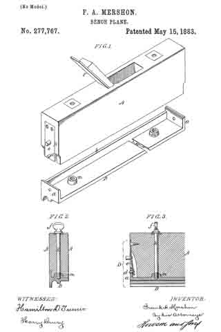
In the accompanying drawings, Figure 1 is a perspective view of my improved molding-plane, showing the sole-plate detached; Fig. 2, a transverse section, and Fig. 3 a longitudinal section of part of the plane.

The stock A of the plane is of wood and the sole-plate B of metal, the under side of this plate having such longitudinal ribs and grooves as the pattern of the molding to be planed may require. The sole-plate has at each end a transverse flange, a, and a longitudinal flange, b, fitted snugly in a recess in the stock, as shown in Fig. 2. There is at each end of the stock a spring-catch, D, for retaining the sole-plate, each catch consisting in the present instance of a spring, e, secured to the stock, and having a pin, d, for entering a hole in the transverse flange a. The stock, it should be understood, is cut away at each end to receive the said flange, and is further cut away to permit the free play of the spring, the flange being so rounded at the upper edge on the inner side that when the stock is applied to the sole-plate by depressing the former onto the latter the springs will yield without being manipulated, and will recoil when the stock reaches the plate, the pins entering the holes in the flanges, and thus holding the two parts of the plane together.

While the spring-retainers will suffice to hold the plate in place, I prefer, as an additional security, to use two set-screws, E, each provided with a head, f, constructed for the convenient turning of the screw by the finger and thumb, the stem of the screw passing through the stock, and its threaded end being adapted to a threaded projection, m, on the sole-plate. This projection is made tapering, and is adapted to an orifice of corresponding form in the under side of the stock. Even if no set-screws are used, I prefer to make these projections on the plate, as they facilitate the adjustment of the stock to its proper position on the plate, and serve as steady-pins for determining the proper lateral and longitudinal relation of the plate to the stock.

It will be seen that whenever a change in the pattern of the molding is required the plate can be readily detached to make way for another, the under side of which conforms with the desired molding, a change of plane irons or bits F being also required. The pins d are preferably tapered, so that they tend to draw the sole-plate firmly to its seat on the stock.

I claim as my invention —

1. A molding-plane in which a stock, A, provided at the ends with spring-catches, is combined with a sole-plate, B, having flanges a, constructed to be retained by the said catches of the stock, substantially as set forth.

2. The combination of the stock A, and a detachable sole-plate having tapering projections adapted to it closely correspondingly-tapered orifices in the stock, and devices, substantially as described, for securing the plate to the stock, substantially as set forth.

3. The combination of the stock A and its spring-catches with the flanged sole-plate and its tapering projections m, adapted to orifices in the stock, substantially as specified.

4. The combination ot the stock A, its spring-catches, the flanged sole-plate, and its tapering projections m, with the set-screws E.

In testimony whereof I have signed my name to this specification in the presence of two subscribing witnesses.

FRANK A. MERSHON.

Witnesses:
HARRY L. ASHENFELTER,
HARRY SMITH.

No. 192,402 – Improvement In Bench-Planes (Clinton L. Adancourt) (1877)

[paiddownloads id=”280″]192402


UNITED STATES PATENT OFFICE.

_________________

CLINTON L. ADANCOURT, OF LANSINGBURG, NEW YORK.

IMPROVEMENT IN BENCH-PLANES.

_________________

Specification forming part of Letters Patent No. 192,402, dated June 26, 1877; application filed December 15, 1876.

_________________

To all whom it may concern:

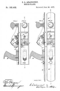
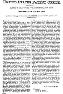
Be it known that I, CLINTON L. ADANCOURT, of the town of Lansingburg, Rensselaer county and State of New York, have invented an Improvement in Bench-Planes, of which the following is a specification:

The nature of my invention consists in forming a wood-plane in adjustable sections, which may be attached to its ends, so as to increase the length of its bearing-surface when required, to vary the uses to be performed by it, and thus make one plane answer a double use by lengthening the same.

It also consists in the manner of attaching and operating the cutting bit or knife to the plane, so that the same may be used to cnt a shaving of greater or less thickness.

My invention consists of these separate features as arranged and constructed, as well as the same combined.

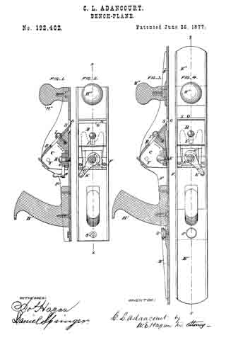
In the accompanying drawings, Figure 1 shows a vertical sectional view of a central section of a plane without the extension sections. Fig. 2 illustrates the same section in a top view looking down upon the plane, with the handle removed. Fig. 3 represents a vertical sectional view with the extension-sections added; and Fig. 4, a top view of the plane with extension-sections added.

Like letters designate like parts in all the figures.

The detachable handles of the plane are designated H’ H”, the cutting bit or knife B, and a hinged bank C, upon which the latter rests, and to which it is attached. The trunnions upon which the bank C is hinged to the side walls of the plane are shown at T; the cutting-edge of the bit at O; the shaving-discharge opening of the plane at S.

The cutting bit or knife is illustrated as attached to the hinged bank by means of a slotted opening in the knife, and a set-screw, as seen at I. Upon the under side of the hinged bank, and against it, so as to more it and the attached bit or knife upon the hinged apex of the former, there is shown an eccentric, e, with a handle, E. This latter is attached to the base of the plane by a screw, K. The extension-sections E’ E” are attached to the central section F by means of lapping and tenoned joints, and are secured and held in place by the set-screws S” S”, passing through the lapping and tenoned points of union, and attaching the handles of the plane.

The manner of operating the device thus formed is as follows: The cutting knife or bit B, as attached to the bank C hinged at T, is shown as in contact, upon its inner edge, with the eccentric e and its handle E, and when this handle is moved in the direction of the arrows, shown upon the eccentric at a”, the motion communicated to the bank in contact is such as to raise or depress the lower end of the bank and knife by moving the same in the direction of the arrows seen at a’ and a”. The shaving-cut will be in proportion to the dip of the bit, and this is arranged by the adjustable eccentric and handle, as it is moved around the fixed pin, the eccentric raising or depressing the cutting end of the knife.

The knife or bit, which is sharpened at both ends, may, if desired, have one end rounded, like the edge of a jack-plane knife, for coarse work, and the other with a straight cutting-edge, like a smoothing-plane, so that the knife may be reversed and used tor either kind of work, and, by the addition of the extension-section, what would serve for a jack-plane body may be changed into that of a jointer, and thus one tool maybe made to answer the purpose of several.

The body of the planes and the extension-sections may be made of either wood, iron, or other suitable material.

Having thus described my invention, what I claim, and desire to secure by Letters Patent, is —

1. In combination, the center knife or bit section F of a plane, and the extension-section E’ E”, to increase the length and base bearing-lines of the plane, as shown and described.

2. In a bench-plane, the hinged bank C, reversible cutting bit or knife B, actuating-eccentric e, and handle E, arranged to operate as described and shown.

3. In a bench-plane, the extension-sections E’ and E”, the center or bit section F, the hinged bank C, cutting bit or knife B, the adjusting-eccentric e, and handle E, arranged to operate as herein described and shown.

Signed at Troy, New York, this 12th day of December, 1876.

C. L. ADANCOURT.

Witnesses:
CHAS. M. DAVIS,
THOS. F. MURNANK.

No. 129,695 – Improvement In Bench-Planes (Thomas Vaughan) (1872)

[paiddownloads id=”201″]129695


UNITED STATES PATENT OFFICE.

_________________

THOMAS VAUGHAN, OF BOSTON, MASSACHUSETTS.

IMPROVEMENT IN BENCH-PLANES.

_________________

Specification forming part of Letters Patent No. 129,695, dated July 23, 1872.

_________________

Specification describing certain Improvements in Bench-Planes, invented by THOMAS VAUGHAN, of Boston, in the county of Suffolk and State of Massachusetts.

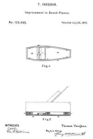
My invention relates to a metallic shoe, into which the wooden body of the plane is fitted and secured by means of cement, said shoe being strengthened by ribs before and behind the cutter, and having grooves or flutings cut in various places upon its inner sides to hold the cement.

In the accompanying drawing, Figure 1 is a plan of the shoe, showing its shape, &c. Fig. 2 is a longitudinal section of the same, the shape and position of the plane being shown by dotted lines.

Similar letters of reference indicate corresponding parts.

a is the bottom of the shoe. a’ a’ are the sides and ends. In is the rib in front of the cutter. c is the rib behind the cutter. d is the opening for the cutter. e e e are flutings or grooves in the sides a’ a’.

This shoe is made of malleable cast-iron, and the body of the plane is cut away so as to fit into the shoe. The plane is secured therein by means of prepared cement, the flutings e e being for the purpose of more thoroughly fastening it, the cement filling into them. The ribs b c are intended to strengthen the shoe, and are very important, as it would without them be very liable to break when meeting with a fall from a considerable height. The casting throughout is of uniform thickness, (probably one~eighth of an inch ,) which gives the plane good proportionate weight. In planes made with my shoe I shall construct the cutter of gaged or uniform thickness throughout, so that the opening d shall retain its size and appearance as the cutter wears off. The cutter will also be secured by a wedge in the ordinary way. My plane (having the shoe) will “clean up” the hardest veneer without requiring a scraper, a few rubs with sand-paper being sufficient for any wood requiring the best French polish even.

A plane made as above-described, and having my shoe, costs about one-half as much as planes now in the market and purporting to do similar work. The wear is, of course, unlimited. The general shape of my shoe may be altered, of course, to fit different planes, such as block-planes; but the other features of the invention will be substantially unaltered.

I do not claim as my invention an iron or entirely metallic plane, but my shoe, in which is set a wooden plane, constructed as above described.

Having thus fully described , my invention, what I claim, and desire to secure by Letters Patent, is —

The combination and arrangement of tl shoe and sides and ends thereof a a’, ribs b c, and flutings e e, substantially as above described, and for the purposes hereinbefore set forth.

THOMAS VAUGHAN.

Witnesses:
HENRY W. WILLIAMS,
E. H. OBER.