No. 511,349 – Plane (Henry Merz) (1893)

UNITED STATES PATENT OFFICE.
_________________
HENRY MERZ, OF POLLASKY, CALIFORNIA.
PLANE.
_________________
SPECIFICATION forming part of Letters Patent No. 511,349, dated December 26, 1893.
Application filed May 1, 1893. Serial No. 472,568. (No model.)
_________________
To all whom it may concern:
Be it known that I, HENRY MERZ, of Pollasky, in the State of California, have invented certain new and useful Improvements in Planes; and I do hereby declare the following to be a full, clear, and exact description of the invention, such as will enable others skilled in the art to which it appertains to make and use the same.
This invention relates to planes for carpenters and the like, and has for its object to improve devices of a similar character which have been heretofore employed.
The invention consists of the detail construction, combination and arrangement of parts, substantially as hereinafter fully set forth, and particularly pointed out in the claims.
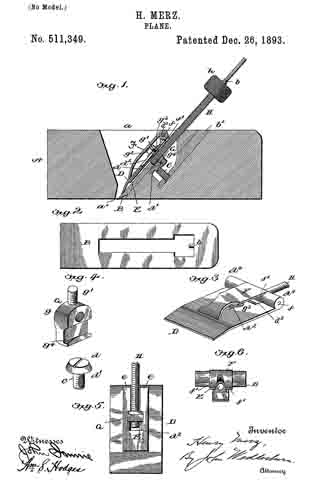
In the accompanying drawings: — Figure 1 is a vertical longitudinal sectional view of my improved plane. Fig. 2 is a view of the cutting blade detached. Fig. 3 is a perspective view of the cap-plate, screw and adjuncts. Fig. 4 is a detail perspective view of a part of the adjusting mechanism. Fig. 5 is a bottom plan view of the cap plate and adjustments in connection therewith. Fig. 6 is a rear end elevation of the clamp and cap plate.
Referring to the drawings, A designates the main or body portion of the plane, having the ordinary opening a which terminates in the transverse slot a’ through which the cutting blade B projects. In this cutting blade is a T-shaped opening, in the outer end of which is a lug b forming a pivot point. In the rear inclined wall of opening a is set a metallic plate b’ into a threaded opening in which is screwed a screw C, the head d of which has an overhanging lower flange d’.
D is a cap plate having a longitudinal slot d2, and a rear central cut away portion d3, and two corresponding sockets d4 on either side of said cut-away portion. To the under side of this cap-plate is fastened a spring-plate E from which extend parallel arms e free at their outer ends.
F is a clamp which fits between sockets d4 and is pivoted by a rod f supported by said sockets. This clamp is rounded at its pivoted end and is provided with two curved cam-lugs f’, which when the clamp is lowered will extend through the cut-away portion of the cap-plate and bear upon the free ends of the spring-arms, causing the latter to bind against the upper surfaces of the cutting blade.
G is a block having upper shoulders g, and a threaded projection g’ which is extended up through slot d2 of cap-plate D and upon it is screwed a nut g2 designed to bind against a washer g3 extending across said slot. The shoulders g are drawn against the lower walls of slot d2, said walls being made tapering. The lower end of block G has an acute lip g4 extending therefrom and designed to engage with the overhanging portion of the headed screw G. The lip is formed into somewhat of a point at about its center so as to securely engage the head of the screw and be held stationary. Through a threaded opening in this block extends a screw rod H, which fits in the T-shaped opening of the cutting blade. A socket in the outer end of this screw-rod receives the lug b. Adjacent to this end is a milled head h, by which the screw rod is readily and easily turned.
The operation of my improved plane is readily understood from what has gone before. To quickly effect the adjustment of the cutting blade the operator raises the clamp so as to release the frictional engagement between the cutting blade and cap-plate, permitting the spring arm to be free. By turning the screw rod the cutting blade can be moved in either direction, the block secured to said cap-plate being stationary by reason of the engagement with the screw C. After the cutting blade has been adjusted the operator closes down the clamp and the cam-lugs thereof bind the spring arms down on said cutting blade, making a firm frictional contact therewith and holding the cutting blade in position. By turning the screw-rod the cutting blade can still be further adjusted but is firmly held at any desired point, the cap-plate being stationary by reason of the engagement of the acute lip of the block with the head of the screw C.
The advantages of my invention are apparent to those skilled in the art to which it appertains, and it will be specially observed that the mechanism employed is simple and not liable to readily get out of order.
I claim as my invention —
1. The herein described plane, comprising a body with a slot or opening therein, a headed stud or screw C arranged obliquely and having a flanged head, a blade having a longitudinally disposed slot with a pivot at the central upper portion of the same, a cap plate with a slot therein in which is adjustably mounted a block formed with a shouldered groove engaging said flanged head of the stud or screw, and having a screw threaded opening extended transversely therethrough, a spring clamp having its upper end pivotally connected to the upper portion of the said cap plate, and a screw rod located in the said longitudinally disposed slot of the blade, and having a milled nut thereon whose upper end engages the pivot at the upper end of said slot in the blade, said nut being located in the slot, substantially as described.
2. The herein described plane comprising a body having a stud or screw therein with a flanged head, a blade having a longitudinally disposed slot with a pivot at the upper terminating wall of the same, a cap plate provided with a slot and having sockets at the upper portions of the same with a central cutaway part, a block adjustably mounted in the slot of the cap plate, and formed with a lower shouldered groove to engage the flanged head of the said stud or screw, a spring clamp mounted on the cap plate and having its upper end pivotally located in the cut-away part of the latter, and pivoted to the sockets thereof, having parallel arms e, which are free and bear against the blade to produce a spring action and a screw rod H mounted in the longitudinally disposed. slot of the blade and extending through the aforesaid block, said screw rod having a milled nut on the upper end thereof for adjusting the blade and having its upper surface rotatably engaging the said pivot, said nut being revoluble in the slot of the blade, substantially as described.
In testimony whereof I have signed this specification in the presence of two subscribing witnesses.
HENRY MERZ.
Witnesses:
W. R. THOMAS,
G. M. McGUIRE.


