
No. 696,414 – Plane (George P. Davidson) (1902)

UNITED STATES PATENT OFFICE.
_________________
GEORGE P. DAVIDSON, OF PORT CHESTER, NEW YORK.
PLANE.
_________________
SPECIFICATION forming part of Letters Patent No. 696,414, dated April 1, 1902.
Application filed October 26, 1901. Serial No. 80,032. (No model.)
_________________
To all whom it may concern:
Be it known that I, GEORGE P. DAVIDSON, a citizen of the United States, residing in Port Chester, in the county of Westchester and State of New York, have invented certain new and useful Improvements in Planes, of which the following is a specification.
This invention relates to planes, and has for its object to provide a plane of improved construction wherein the advantages appertaining to a metal plane-stock and to a wooden plane-stock are combined.
Another object of the invention is to provide a plane having a sole of wood and metal.
Another object is to provide a plane wherein the plane-iron is impressed and held in position by contact with wood and metal.
Another object is to provide a plane wherein the plane-iron is held in place by contact with wood positioned by metal.
Another object of the invention is to provide a plane possessing the desirable characteristics of an old-fashioned plane, but ernbodying the advantages of a metal plane.
Many users of planes prefer a plane having a wooden sole, because they regard a plane working with wood to wood as running more smoothly and easier than one having a metal sole; but the tendency of a wooden sole upon coming in contact with a knot, or if a cornposite piece of wood is being planed with a piece of wood which is harder than the wood surrounding it, is to jump. The metal sole, however, has more of a tendency to hang to its work and keep the plane-iron down into the wood irrespective of knots or denser texture. Having in view this fact, I have pro-
vided a plane having a combined wooden and metal sole, so that the bearing-surface may be made of wood for the purpose of securing easy running, but with suflicient iron or other metal on the sole to cause the plane to hang to its work when obstacles are encountered.
In metal planes it has been found impracticable to make the plane-iron as heavy and substantial as the plane-irons heretofore employed in the old-fashioned wooden planes, the plane-irons of the modern iron plane being of such thin material that they heat in the work, frequently drawing the temper.
My invention provides a plane wherein the old-fashioned plane-iron may be employed, held in place by a wooden wedge, wedging the back of the plane-iron against a wooden block, but yet where the bearing-surfaces for those blocks are made of metal, thus obviating all liability of the bearing-surfaces getting away from their proper positions or splitting or distorting the main structure by incessant adjustment of the parts.
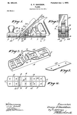
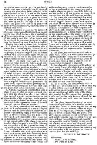
In the drawings accompanying and forming part of this specification, Figure 1 is a central longitudinal sectional view of a form of my invention embodied in a block-plane. Fig. 2 is a cross-section in the line a a of Fig. 1. Fig. 3 is a perspective of the metal frame of the plane. Fig. 4 is a plan view of the sole of the plane, and Fig. 5 is one of the detached wooden plates.
Similar characters of reference designate corresponding parts in the various figures.
Referring to the drawings, my invention is shown as applied to a plane wherein the stock (designated in a general way by A) comprises a frame, (designated in a general way by B,) which frarne is preferably composed of a single casting having side members 6 6, which side members are connected by integral bars 7 7, so disposed as to leave a mouth 8, the stock at the back of which mouth is provided with a seat or rest 9 for the plane-iron and a positioning bar or rest 10 for the plane-handle block. The side members are also provided with lugs 11 11, adapted for the wedge to bear against. Suitable chambers 12 are provided in the sole ot’ the frame to receive blocks or plates 13, formed of wood, disposed in such chambers and between the side members and suitably-formed ridges 14 of the frame, the side members, mouth, ridges, and wooden plates making a composite sole.
The upper side of the plane is provided with a handle 15, secured to a block 16, which block is effective to rest upon the cross-bars 7 7 and against the bar 10 for positioning the same, into which handle-block screws passing through the sole-plates may enter, the front part of the frame being also provided with a block 17 and handle 18, into which block the screws of the forward plates may enter. After the plane-stock has been assembled the wood and metal of the sole may be made smooth in any convenient manner, as by grinding. A plane-iron 19 of any ordinary or suitable construction may be employed, which may have a suitable cap 20 screwed thereto, the plane-iron being adapted to lie upon the seat or rest 9 formed on the frame and against a portion 16′ of the wooden handle-block and to be held in place by means of a wooden wedge 21, lying upon the cap and passing behind the lugs 11 11 on the frame, the plane-iron thus being positioned by immovable metal parts, but being held by contact with wood.
By my invention a plane may be produced of greater strength and lightness than planes now in use, which is due to the organization of the component parts, and the cooperation of the parts is such that lighter metals may be employed in the construction of a plane than has heretofore been found practicable.
Having described my invention, I claim —
1. A plane having, in combination with a plane-iron, a metal support therefor in direct contact with the iron adjacent to its cutting edge; a wooden support also in direct contact with the plane-iron above and on the same side of the iron as the said metal support; a metal reaction member on the opposite side of the plane-iron; and a wooden clamping-wedge insertible between and contacting with the opposed surfaces of the said iron and the said reaction member.
2. In a plane, the combination of a plane-stock having a sole comprised of wooden and of metal portions, the metal portion forming a rest for the lower end of the plane-iron; a wooden portion secured to the plane-stock and forming part thereof, and effective to form a support for the central portions of the plane-iron; lugs on the metal portion; and a wooden wedge interposed between such lugs and plane-iron to hold such iron in place.
3. A plane having, in combination with a plane-iron, a wooden support in direct contact with the plane-iron above the cutting edge thereof; a metal reaction member on the opposite side of the plane-iron; and a wooden clamping-wedge insertible between and contacting with the opposed surfaces of the said iron and the said reaction member.
4. In a plane, the combination with a plane-iron and a metal frame, of a metal support for said iron in direct contact therewith adjacent to its cutting edge; a wooden support also in direct contact with the plane-iron above and on the same side of the iron as the said metal support; a metal reaction member on the opposite side of the plane-iron; and a wooden clamping-wedge insertible between and contacting with the opposed surfaces of the said iron and the said reaction member.
5. In a plane, the combination with a metal frame; a wooden sole; and a plane-iron, of a metal support for said iron extending from the frame and in direct contact with the iron adjacent to its cutting edge; a wooden support also in direct contact with the plane-iron above and on the same side of the iron as the said metal support; a metal reaction member on the opposite side of the plane-iron; and a wooden clamping-wedge insertible between and contacting with the opposed surfaces of the said iron and the said reaction member.
6. In a plane, the combination with a metal frame; a composite sole; and a plane-iron, of a metal support for said iron extending from the frame and in direct contact with the iron adjacent to its cutting edge; a wooden support also in direct contact with the plane-iron above and on the same side of the iron as the said metal support; a metal reaction member on the opposite side of the plane-iron; and a wooden clamping-wedge insertible between and contacting with the opposed surfaces of the said iron and the said reaction member.
7. In a plane, the combination with a metal frame, and a wooden sole, of a wooden handle-supporting block to which said wooden sole is secured and between which the frame is clamped.
8. In a plane, the combination with a chambered metal frame, of a wooden sole comprising strips inlaid in the chambers of the frame; and a wooden handle-supporting block to which said wooden sole is secured and between which the frame is clamped.
9. In a plane, the combination with a chambered metal frame, of a plane-iron, a wooden sole comprising strips inlaid in the chambers of the frame in front of and at the rear of the said plane-iron, and wooden handle-supporting blocks also located in front of and at the rear of said plane-iron, and to which the wooden sole is secured and between which and said sole the frame is clamped.
10. In a plane, the combination with a wooden sole, of a metal frame in which said wooden sole is inlaid and which is provided with a rubbing-surface encircling the wooden sole at the sides and at the ends of the plane, and wooden handle-supporting blocks to which said wooden sole is secured, and between which and said sole the frame is clamped.
11. In a plane, the combination with a metal frame and a plane-iron, of a wooden sole inlaid in said frame; a metal support for the plane-iron in direct contact therewith adjacent to its cutting edge; a wooden support also in direct contact with the plane-iron above and on the same side of said iron as the said metal support; lugs extending from opposite sides of the metal frame and constituting a reaction member located on the side of the plane-iron opposite to which said metal support and wooden support are situated, and a wooden clamping-wedge insertible between and contacting with the opposed surfaces of the said iron and the said lugs.
GEORGE P. DAVIDSON.
Witnesses:
WILLIAM G. SLATER,
DE WITT H. LYON.